标签:des style blog http color os
Methods and arrangements for object identification. An identification request is received from different objects of a network. Attributes and values of each object are ascertained, and at least one attribute-value pair from each object is filtered out. An ID is generated for each object based on at least one remaining attribute-value pair from the filtering.
Increasingly, objects are being connected electronically and/or communicatively in ways that previously were the province mostly of computers. As such, the term "Internet of Things" (IoT) has come to describe a dynamic network of globally connected things, entities, devices, items or objects. An illustrative and non-restrictive example can involve a company or enterprise in which numerous items are communicatively interconnected such as computers, mobile devices (e.g., phones, laptops or tablets), lighting and climate control systems, cars or other vehicles and "smart" appliances (e.g., refrigerators, televisions) and some or all can be controlled or interacted with from one place or another. Other examples involve systems that are distributed over disparate geographical areas as opposed to just one physical location. As the number and complexity of interconnected items in an IoT has the potential to grow considerably, the tracking, monitoring and identification of each interconnected item becomes all the more challenging.
In summary, one aspect of the invention provides a method comprising: receiving an identification request from different objects of a network; ascertaining attributes and values of each object; filtering out at least one attribute-value pair from each object; and generating an ID for each object based on at least one remaining attribute-value pair from the filtering.
Another aspect of the invention provides an apparatus comprising: at least one processor; and a computer readable storage medium having computer readable program code embodied therewith and executable by the at least one processor, the computer readable program code comprising: computer readable program code configured to receive an identification request from different objects of a network; computer readable program code configured to ascertain attributes and values of each object; computer readable program code configured to filter out at least one attribute-value pair from each object; and computer readable program code configured to generate an ID for each object based on at least one remaining attribute-value pair from the filtering.
An additional aspect of the invention provides a computer program product comprising: a computer readable storage medium having computer readable program code embodied therewith, the computer readable program code comprising: computer readable program code configured to receive an identification request from different objects of a network; computer readable program code configured to ascertain attributes and values of each object; computer readable program code configured to filter out at least one attribute-value pair from each object; and computer readable program code configured to generate an ID for each object based on at least one remaining attribute-value pair from the filtering.
The disclosure now turns to?FIGS. 1-5. It should be appreciated that the processes, arrangements and products broadly illustrated therein can be carried out on or in accordance with essentially any suitable computer system or set of computer systems, which may, by way of an illustrative and non-restrictive example, include a system or server such as that indicated at?12′ in?FIG. 7. In accordance with an example embodiment, most if not all of the process steps, components and outputs discussed with respect to?FIGS. 1-5?can be performed or utilized by way of a processing unit or units and system memory such as those indicated, respectively, at?16′ and?28′ in?FIG. 7, whether on a server computer, a client computer, a node computer in a distributed network, or any combination thereof.
To facilitate easier reference, in advancing from?FIG. 1?to and through?FIG. 5, a reference numeral is advanced by a multiple of 100 in indicating a substantially similar or analogous component or element with respect to at least one component or element found in at least one earlier figure among?FIGS. 1-5.
Generally, many devices have long been presumed to be heterogeneous with respect to each other, such as desktop devices, mobile communicators, digital assistants, wrist watches, game consoles, clothing, consumer electronics (e.g., TVs, radios, and refrigerators), cars, sensors, smart meters, and video surveillance equipment, to name but a few examples. However, advancements in the realm of networking, sensors, actuators, radio frequency identification (RFID) and near field communication (NFC) technologies have made it possible to connect various devices and real-world objects and or virtual objects. Smart applications, as they have evolved, have increasingly demanded that heterogeneous devices be in a position to discover, identify and communicate with each other so as to able to exchange data and cooperate to undertake predetermined tasks. However, a reliable, standardized scheme for permitting the identification of heterogeneous devices per se and with respect to each other has long been elusive.
In logistics and asset management, an object is often identified by an RFID tag, while a separate database (usually resident at an RFID manufacturer domain) contains details which map tags to objects. As such, an RFID reader typically reads a tag and then derives from the tag the location of the associated object. The reader then contacts the manufacturer database to fetch the details of the object. Accordingly, if the RFID tag on an object is faulty in any way or possibly has been destroyed, then object details cannot be obtained. Further, if a faulty RFID tag is replaced by a new RFID tag, then the manufacturer database (the existing one, or even a new one corresponding to a new manufacturer) needs to be updated. It can be appreciated that a process such as this can be inordinately time-consuming and complex.
Another challenge often encountered is that devices tend to be identifiable solely by hardware identifiers assigned by a manufacturer. Thus, not only might such identifiers be difficult to assimilate in a network outside of the context of a manufacturer‘s own network, but they might be private or proprietary identifiers and may present a compromise in security to the manufacturer if revealed to other entities. Accordingly, hardware-dependent identifiers do not lend themselves to a flexible, integrable identification scheme that would allow ready communication with and among objects deriving from different manufacturers.
Conventionally, devices are identified by manufacturer-assigned hardware identifiers, and security concerns tend to preclude making such hardware public. Consequently, difficulties are presented in discovering devices and enabling communication between heterogeneous devices. For instance, multiple identification schemes might be in play (with various types of commercially known identifiers such as EPC, uID, ID@URI, Zigbee, GUID, etc.), making integrative identification across devices and types of devices difficult if not impossible.
In accordance with at least one embodiment of the invention, there is broadly contemplated herein an identification scheme which is independent of existing schemes and can serve to unite and coordinate disparate schemes. Particularly, an attribute-based scheme, variously referred to herein as "GenID" (Generated ID), is contemplated for objects in the domain of the Internet of Things.
As such, in accordance with at least one embodiment of the invention, GenID generates logical identifiers for objects, from hardware-independent information, in a way that embeds meaningful information about objects. Also broadly contemplated herein is an identity management system (IMS) for objects, wherein the GenID scheme is implemented.
In approaching an identification scheme in accordance with at least one embodiment of the invention, it is recognized that a device may already have several identifiers associated with it, such as (by way of illustrative example): manufacturer ID, network address, temporary local ID (as may be the case in adhoc networks), ID‘s of sensors or actuators, and/or possibly many others. Thus, solutions in accordance with at least one embodiment of the invention address this problem, as well as challenges associated with composite devices, replaceable parts (and their own associated ID‘s), and the possibility of the division and aggregation (or re-aggregation) of parts). An allocation mechanism, as broadly contemplated herein, also affords a level of flexibility that readily accommodates changes in identities.
In an identification scheme according to at least one embodiment of the invention, objects (physical and/or logical entities) can be understood as being uniquely identifiable by a set of attributes, wherein "attribute" is a category in which an object can be classified (e.g., "color"). A value assigns an object‘s classification within a category, e.g., "red" within "color". Thereupon, an attribute and its corresponding value form an "av-pair", or a key-value pair which characterizes an object (thus, e.g., "color-red").
In accordance with at least one embodiment of the invention, unique identification of an object comes about from applying a functional transformation to result in an aggregate or encompassing identifier (here throughout referred to as a logical identifier) on a set of av-pairs that describe the properties of an object. More particularly, a method (GenID) in accordance with at least one embodiment of the invention undergoes several stages culmination in the generation of a logical identifier, in a manner now to be described in more detail.
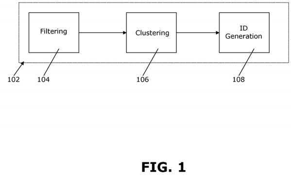
In accordance with at least one embodiment of the invention, and as shown schematically in?FIG. 1, an ID generator?102(for effecting a GenID solution) involves three steps for identifying objects via their attributes: filtering?104, classifying into clusters?106?and generating logical identifiers?108. Particularly, attributes are filtered (104) based on their entropy values, such that the most useful set of av-pairs from the all attribute-value pairs of an object are extracted for use in ID generation. Thence, objects are identified at a class level using incremental, real-time, categorical clustering algorithms (106). Finally, in generating logical identifiers (108), ID‘s are generated for objects based on system version, agency specific information, attribute-value set and class level information.
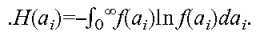
In accordance with at least one embodiment of the invention, the filtering step?104?involves eliminating unimportant and unnecessary attributes. This is based on the entropy [1] of attributes and requirements of the attribute, wherein entropy can be defined as the measure of uncertainty or structuredness of the attribute (for background purposes see, e.g., C. E. Shannon, "A mathematical theory of communication", Bell Labs Technical Journal, 1948; http://cm.bell-labs.com/cm/ms/what/shannonday/shannon1948.pdf.)
First, let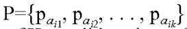 be the set of probabilities of existence of K possible values of attribute
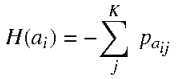
 . Then the entropy of attribute
  ?denoted as
  is defined as
In ?,
?, 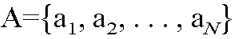 is the universal set of N attributes devices can specify. It can be assumed that A is known. When the value set of the attribute
  ?is continuous with probability density function
  , entropy can be defined as
Continuing, in accordance with at least one embodiment of the invention, in the context of databases and information retrieval theory, it can be stated that an attribute with larger value domain normally divides the database into smaller classes and may have a large entropy value. A lower entropy value indicates the attribute divides database into few larger classes, while an attribute with an intermediate entropy value can generally be regarded as useful. Therefore, two threshold values are defined, low threshold (LB) and upper threshold (UB). Those attributes with an entropy value less than LB and those with an entropy value greater than UB can accordingly be discarded.
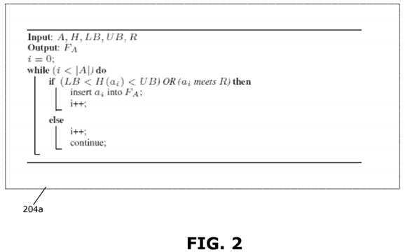
In accordance with at least one embodiment of the invention, there may be cases when entropy of an attribute is not in an acceptable range, but there may be a requirement to include (or not include) them in a follow-up procedure of ID generation. This may happen, for example, when a new device enters into the market or some existing device is modified to the extent that a new attribute starts qualifying it. There may be other situations when privacy and security requirement of an attribute compels it to exclude the attribute in ID generation process these can be noted as system-specific requirements R. Accordingly, 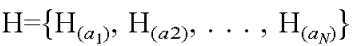 denotes the set of entropies of all attributes, and FA?is the set of filtered av-pairs. With this in mind,?FIG. 2?shows a filtering algorithm?204a?that can be employed.
In accordance with at least one embodiment of the invention, and returning to?FIG. 1, clustering step?106?involves partitioning devices into classes (or clusters) such that those devices belonging to the same cluster are similar in at least some ways, and those belonging to different clusters are dissimilar in at least some ways. As such, devices are clustered based on their av-pairs, and on two levels (or in two distinct senses), wherein "Level 0" clustering is based on the attributes of devices and "Level 1" clustering is based on the av-pairs characterizing devices.
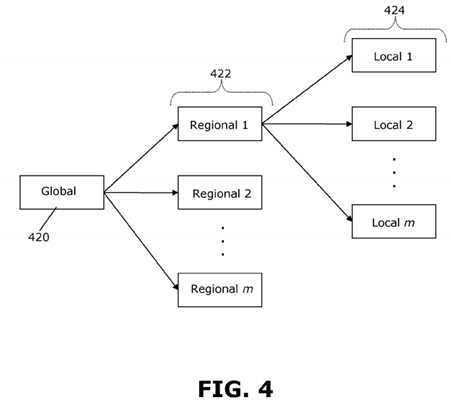
Thence, in accordance with at least one embodiment of the invention, the step of ID generation (or generating a logical identifier)?108?involves a few sub-segments. Accordingly,?FIG. 3?depicts a generated ID?310?with several constituent components or fields. (It should be understood that, generally, the ID?310?may include numbers or letters or a combination of both.) First, a "version" field?312?identifies the version number of the ID generation system. Thence, a segment of agencies-specific information?314?is generated from a GenID management hierarchy, whereby local level identifiers are able to serve as global level identifiers. More particularly, referring to?FIG. 4, a global, regional and local agency hierarchy is broadly contemplated wherein such information can be incorporated and hence be included as part of the ID. As shown in FIG. 4, a global ID manager?420?is in communication with m constituent regional ID managers?422, any or all of which can be in communication with n constituent local ID managers?424. Generally, it can be appreciated that this type of hierarchy may be applicable to a globally managed network.
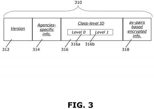
Returning to?FIG. 3, in accordance with at least one embodiment of the invention, ID?310?includes a segment of class level identification?316, which in turn involves the cluster ID as described here above. Through class level identification information, it is possible to identify the group to which a device belongs, and two parts are included, as touched on hereinabove: Level 0 Cluster ID?316?a?and Level 1 Cluster ID?316?b.?The final segment of ID?310?is one of av-pairs based encrypted information?318, generated in three steps. First, in a first step of attribute encoding, given a universal attribute set A and corresponding set of attribute weights W, the attributes in A are ordered in accordance with weights W and each attribute is encoded using Huffmann encoding (see, e.g., D. A. Huffman, "A Method for the Construction of Minimum-Redundancy Codes", Proceedings of the I.R.E., September 1952, pp 1098-1102) where weights play the role of frequencies. With respect to an object, certain attributes are chosen, pseudo-randomly, explicitly, with corresponding values chosen implicitly. Then, in a second step of key generation, encodings of the chosen attributes are used as seeds to form a 128 bit key of the object and, in encryption, the value of the randomly chosen attributes for the object are then encrypted using the keys. At that point, in the third and final step, the 128-bit key generated for the object in the second step is used to encrypt the GenID using an AES (Advanced Encryption Standard) encryption scheme (for background purposes see, e.g., Joan Daemen, Vincent Rijmen, "The Design of Rijndael: AES—The Advanced Encryption Standard." Springer, 2002).
FIG. 5?schematically illustrates a general system architecture, including an Identity Management System (IMS)?524, in accordance with at least one embodiment of the invention. Included is an ID generator module?502?which can generate a logical identifier ID as described heretofore. This is in communication with an ID cache?530?and objects database?532. A destroyer module?526, on the other hand, is configured to destroy or erase the ID of an object upon deregistration of the object while an updater module?528?can update the ID or metadata associated with an object. These components and steps will be better understood in accordance with the discussion herebelow.
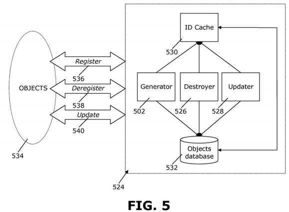
Thus, accordance with at least one embodiment of the invention, objects?534?can register (536) to IMS?524?in an initial step before receiving an ID. During registration?536, then, objects?534?can specify av-pairs and metadata about themselves such as protocols understood, services deployed, etc. Generator?502?generates a unique logical ID (e.g., in a manner as described hereinabove), which in a response step of registration?536?is returned to the corresponding object?534. Additionally, an entry is allotted in the ID cache?530?pointing to a record of the object?524?in database?532.
In accordance with at least one embodiment of the invention, objects?534?can then, at any point, deregister (538) from the IMS?524?and/or have their metadata updated (540). Each of these steps (538/540) is two-way in nature, involving request to the IMS?524?and confirmation therefrom. In updating (540), the object sends a request to update its records, using its allocated unique ID to gain access to IMS?524?The updater module?528?then finds the corresponding entry in the ID cache530?and retrieves the pointer to database?532, thereafter updating records in either or both of the cache and database (530/532) as needed (e.g., using a suitable data exchange protocol). In deregistration (538), once an object?534?requests for deregistration and gains access to IMS?524?via its unique ID, deregistration module?526?finds the corresponding in the ID cache?530, retrieves the pointer to database?532, and deletes both the object record from database?532?and the corresponding entry from ID cache?530.
FIG. 6?sets forth a process more generally for object identification, in accordance with at least one embodiment of the invention. It should be appreciated that a process such as that broadly illustrated in?FIG. 6?can be carried out on essentially any suitable computer system or set of computer systems, which may, by way of an illustrative and on-restrictive example, include a system such as that indicated at?12′ in?FIG. 7. In accordance with an example embodiment, most if not all of the process steps discussed with respect to?FIG. 6?can be performed by way a processing unit or units and system memory such as those indicated, respectively, at?16′ and?28′ in?FIG. 7.
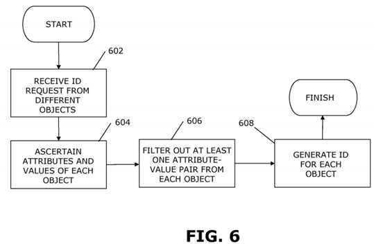
As shown in?FIG. 6, an identification request is received from different objects of a network (602). Attributes and values of each object are ascertained (604), and at least one attribute-value pair from each object is filtered out (606). An ID is generated for each object based on at least one remaining attribute-value pair from the filtering (608).
Referring now to?FIG. 7, a schematic of an example of a cloud computing node is shown. Cloud computing node?10′ is only one example of a suitable cloud computing node and is not intended to suggest any limitation as to the scope of use or functionality of embodiments of the invention described herein. Regardless, cloud computing node?10′ is capable of being implemented and/or performing any of the functionality set forth hereinabove. In accordance with embodiments of the invention, computing node?10′ may not necessarily even be part of a cloud network but instead could be part of another type of distributed or other network, or could represent a stand-alone node. For the purposes of discussion and illustration, however, node?10′ is variously referred to herein as a "cloud computing node".
In cloud computing node?10′ there is a computer system/server?12′, which is operational with numerous other general purpose or special purpose computing system environments or configurations. Examples of well-known computing systems, environments, and/or configurations that may be suitable for use with computer system/server?12′ include, but are not limited to, personal computer systems, server computer systems, thin clients, thick clients, hand-held or laptop devices, multiprocessor systems, microprocessor-based systems, set top boxes, programmable consumer electronics, network PCs, minicomputer systems, mainframe computer systems, and distributed cloud computing environments that include any of the above systems or devices, and the like.
Computer system/server?12′ may be described in the general context of computer system-executable instructions, such as program modules, being executed by a computer system. Generally, program modules may include routines, programs, objects, components, logic, data structures, and so on that perform particular tasks or implement particular abstract data types. Computer system/server?12′ may be practiced in distributed cloud computing environments where tasks are performed by remote processing devices that are linked through a communications network. In a distributed cloud computing environment, program modules may be located in both local and remote computer system storage media including memory storage devices.
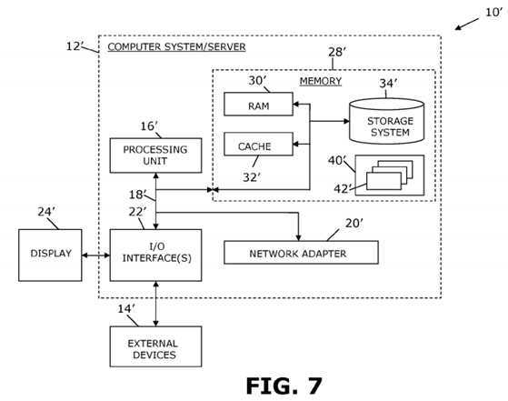
As shown in?FIG. 7, computer system/server?12′ in cloud computing node?10?is shown in the form of a general-purpose computing device. The components of computer system/server?12′ may include, but are not limited to, at least one processor or processing unit?16′, a system memory?28′, and a bus?18′ that couples various system components including system memory?28′ to processor?16′.
Bus?18′ represents at least one of any of several types of bus structures, including a memory bus or memory controller, a peripheral bus, an accelerated graphics port, and a processor or local bus using any of a variety of bus architectures. By way of example, and not limitation, such architectures include Industry Standard Architecture (ISA) bus, Micro Channel Architecture (MCA) bus, Enhanced ISA (EISA) bus, Video Electronics Standards Association (VESA) local bus, and Peripheral Component Interconnects (PCI) bus.
Computer system/server?12′ typically includes a variety of computer system readable media. Such media may be any available media that is accessible by computer system/server?12′, and it includes both volatile and non-volatile media, removable and non-removable media.
System memory?28′ can include computer system readable media in the form of volatile memory, such as random access memory (RAM)?30′ and/or cache memory?32′. Computer system/server?12′ may further include other removable/non-removable, volatile/non-volatile computer system storage media. By way of example only, storage system?34′ can be provided for reading from and writing to a non-removable, non-volatile magnetic media (not shown and typically called a "hard drive"). Although not shown, a magnetic disk drive for reading from and writing to a removable, non-volatile magnetic disk (e.g., a "floppy disk"), and an optical disk drive for reading from or writing to a removable, non-volatile optical disk such as a CD-ROM, DVD-ROM or other optical media can be provided. In such instances, each can be connected to bus?18′ by at least one data media interface. As will be further depicted and described below, memory?28′ may include at least one program product having a set (e.g., at least one) of program modules that are configured to carry out the functions of embodiments of the invention.
Program/utility?40′, having a set (at least one) of program modules?42′, may be stored in memory?28′ by way of example, and not limitation, as well as an operating system, at least one application program, other program modules, and program data. Each of the operating system, at least one application program, other program modules, and program data or some combination thereof, may include an implementation of a networking environment. Program modules?42′ generally carry out the functions and/or methodologies of embodiments of the invention as described herein.
Computer system/server?12′ may also communicate with at least one external device?14′ such as a keyboard, a pointing device, a display?24′, etc.; at least one device that enable a user to interact with computer system/server?12; and/or any devices (e.g., network card, modem, etc.) that enable computer system/server?12′ to communicate with at least one other computing device. Such communication can occur via I/O interfaces?22′. Still yet, computer system/server?12′ can communicate with at least one network such as a local area network (LAN), a general wide area network (WAN), and/or a public network (e.g., the Internet) via network adapter?20′. As depicted, network adapter?20′ communicates with the other components of computer system/server?12′ via bus?18′. It should be understood that although not shown, other hardware and/or software components could be used in conjunction with computer system/server?12′. Examples, include, but are not limited to: microcode, device drivers, redundant processing units, external disk drive arrays, RAID systems, tape drives, and data archival storage systems, etc.
SRC=https://www.google.com.hk/patents/US20130198185
Attribute-based identification schemes for objects in internet of things,布布扣,bubuko.com
Attribute-based identification schemes for objects in internet of things
标签:des style blog http color os
原文地址:http://www.cnblogs.com/coryxie/p/3864036.html