标签:des style blog http color os strong io
A method implemented by a network device residing in a service domain, wherein the network device comprises an information centric networking (ICN) transport layer and a service access layer (SAL) for handling context-aware service logistics and service mobility overlaid on the ICN transport layer, the method comprising receiving, in the ICN transport layer, a message comprising a service request that originates from a user equipment (UE), in the SAL, retrieving, from the service request, contextual information relevant to the UE or an access network connected to the UE, determining, based on the contextual information, one or more services needed to execute the service request, and determining one or more service identities (SIDs) each of which identifies one of the one or more services.
Service oriented architecture (SOA) related technologies have been around since late 1990s, and many current web services take advantage of this architecture. SOA introduces a subscriber-publisher model that provides loose coupling of service access interfaces and service implementations. SOA may comprise three players including a service consumer, a service provider, and a service broker, each inter-linked with another. Some SOA services may be described in a standard web service description language (WSDL). Web services may be resolved through a directory service referred to as universal description, discovery and integration (UDDI) registry, which acts as the service broker. A simple object access protocol (SOAP) may provide a binding relation between several decentralized web services. In addition to loose binding between service consumers and producers, the SOA may enable dynamic service discovery and delivery. SOA may provide a guideline for designing a service centric networking (SCN) framework which may be realized over any universal network layer, such as an information centric networking (ICN) transport layer.
From an end host perspective, current Internet Protocol (IP) networks, to an extent, may pre-bind an identity of a service and a location of the service. In other words, when resolving a service name, a domain name system (DNS) server may return an IP address which may directly locate the service or identify some other proxy (e.g. load balancer) that further resolves the service. Therefore, when a service migrates and binds to a new IP address, the existing sessions may be interrupted. An application running the service may accept dynamic updating, but it may need host-level stack modifications. Further, pre-binding may limit user mobility and device mobility, and thus prevent hosts from exploiting multi-homing features.
In one embodiment, the disclosure includes a method implemented by a network device residing in a service domain, wherein the network device comprises an information centric networking (ICN) transport layer and a service access layer (SAL) for handling context-aware service logistics and service mobility overlaid on the ICN transport layer, the method comprising receiving, in the ICN transport layer, a message comprising a service request that originates from a user equipment (UE), in the SAL, retrieving, from the service request, contextual information relevant to the UE or an access network connected to the UE, determining, based on the contextual information, one or more services needed to execute the service request, and determining one or more service identities (SIDs) each of which identifies one of the one or more services.
In another embodiment, the disclosure includes a network device functioning as a heterogeneous access point (H-AP), the network device comprising at least one receiver configured to receive a publishing message that advertises a new service, a service access controller (SAC) coupled to the receiver and configured to add a new entry to a service access strategy table (SAST) in the SAC to reflect availability of the new service, and update the publishing message to generate an updated publishing message which comprises the H-AP as a prefix (e.g., a resolution prefix), and at least one transceiver coupled to the SAC and configured to forward the updated publishing message, and transmit, to a second network device functioning as an SRN, a notification message indicating that the new service is available from the H-AP.
In yet another embodiment, the disclosure includes a method implemented by a network device functioning as a point of attachment (PoA), the method comprising receiving, from a UE, a request for network registration, retrieving, from the request, access context of the UE which identifies the UE, updating one or more data structures in the PoA to include the access context and a default priority set for the UE, sending, to the UE, a prefix of the PoA as a response to the request, and sending, to a second network device functioning as an H-AP, a message notifying the H-AP of the registration request from the UE, wherein the PoA has registered with the H-AP.
Information Centric Networking (ICN) is a network model or architecture in which the focus is on locating and providing information to users rather than on connecting end hosts that exchange data. For example, in ICN-based communication, application requests may bind to the network layer over named entities (e.g., content object, user device, service) and de-couple its location and address information, which may eliminate the need for pre-binding. For another example, name-based routing with in-network caching may allow mobility to be handled in a scalable, efficient, and flexible manner. For yet another example, security credentials appended to the ICN packet may allow location independence of data and/or services, thereby helping to realize agile information dissemination.
Since an information exchange may be considered a case of service delivery, best effort services can be handled by an ICN layer, while services with performance constraints may be given special handling. Applying the SOA paradigm in an ICN environment may take advantage of the name-based networking approach to support dynamism at both a service producer end and a consumer end. Traditionally, services may be delivered by pre-provisioned end servers to which user requests are mapped. On the other hand, a service-centric ICN framework equipped with an ability to interpret user requests, intelligent caching and computing, and location-independent content delivery, may be leveraged to enable intelligent service management.
This disclosure teaches a service centric networking (SCN) framework over an ICN transport architecture to resolve a service name and a locator for a service provided in the architecture dynamically based on contextual information of a consumer of the service. Such contextual information may be relevant to a user equipment (UE) from where the service request is originated, an access network (e.g., a wireless, wired, or mobile connection) to which the UE is connected, or other information including location, time, social relationships, or combinations thereof. In the ICN-based SCN framework, an ICN-service layer (SL) is overlaid on an ICN transport layer, and the ICN-SL may be configured to handle context-aware service logistics and service mobility which will be further described. In a disclosed embodiment, to process a service request, a two-level decomposition approach may be used to first determine one or more services needed to process the service request, and then to decompose a service into a plurality of tasks, which represent instances of the service that may be available in a local service domain. A service routing mechanism may be used to navigate services as a result of the decomposition, which may be performed by a network device referred to herein as a service routing node (SRN), functioning as an ICN edge gateway with an ICN transport layer and additionally having an ICN-SL overlaid on the ICN transport layer. An SRN may be part of a generic service access point (G-SAP) platform, which may comprise other network functions such as a heterogeneous access point (H-AP) and a point of attachment (PoA). Components of the G-SAP platform may be deployed in an internet service provider (ISP) service domain and/or a third-party service domain to achieve various features disclosed herein, including context-aware service management, service routing management, and service producer mobility management.
There may be various motivations of building an ICN-based SCN framework. With an ICN-based Future Internet architecture, services may be more decentralized, around which information exchange may be built. ICN may lend itself to a platform that can meet this requirement since an ICN infrastructure may interpret a service prefix and may try to satisfy it with its local or global knowledge of content, computing and storage resources. From a service publishing perspective, the ICN framework may be flexible to enable anyone to publish a service from any device, and to make the service discoverable through a service discovery mechanism, both locally and globally. Therefore, from a consumer application point of view, service access may be transparent. This may be enabled through a localized service access point (SAP), which may be an ICN-enabled service gateway of a domain to which a consumer is currently registered. This gateway may have a SAP to manage service requests from its consumers. As a result, the consumer may be unaware or oblivious about which server is providing the service, but only needs to know that the returned content is a result of the service request.
More specifically, a first motivation of building an ICN-based SCN framework is to virtualize the ICN network as a multi-service network. In other words, service application may be deployed anywhere on a need basis over end hosts or the network infrastructure. A SL may be overlaid on an ICN transport layer and included in an ICN router that acts as a SAP. The SL may have functionalities for service management, such as transport-level services, service publish, service discovery, service resolution, service orchestration and composition, and context-aware management. In particular, the SL may also handle service-level routing decisions, which may be a special process of context-aware management and service orchestration. Service routing decision may be able to manage the service mobility in terms of data or application mobility.
A second motivation of building an ICN-based SCN is to develop a framework adaptive to device mobility and context changes. The framework may support not only services provided by large commercial data centers or clouds, but also services published by personal mobile devices. Device mobility management may support a service-level late-binding to its server‘s location within or outside a domain based on consumer properties.
Some of the principles in a SCN framework may include, but are not limited to: 1) loose coupling of service access interfaces and the corresponding implementation; 2) communication of services with each other through a standard interface, such as Simple Object Access Protocol (SOAP); 3) transparency of service logics to the external world such as the public internet; 4) decomposition of a request into multiple services requests, which may be reassembled as potentially complex service logic; and 5) ability to discover and reuse services.
In an ICN-based SCN framework, on the application level, the service layer may abstract itself as a "socket" that an ICN application may leverage to meet both transport and service level objectives. Transport spans control over aspects such as receiver-oriented transport, request reliability and service level objectives including supporting for both consumer and producer dynamism, such as mobility, service management functions. Examplary service management functions may include service publishing, service discovery, request service, and multiplexing and/or de-multiplexing functions that span application to user to device-level requirements.
Furthermore, services may be dynamically provisionable in an ICN-based SCN framework. The dynamism may include the ability to name a service, associate desirable properties to the service, publish the service so that it is discoverable, and resolvable in an optimal approach. Moreover, the framework may be adaptive to user context and may ensure the quality of experience (QoE) for the user. The contextual aspects may include mobility of user or device, and access network change within or between service providers.
FIG. 1A?illustrates an embodiment of an ICN-based SCN framework or architecture?100, in which disclosed embodiments may operate. The framework?100?may be formed by interconnecting a number of service domains, such as domains?110,120,?130, and?140, which may be overlaid on an ICN core network?150, as shown in?FIG. 1A. These service provisioning domains may be classified into two or more categories. As a first exemplary category, third-party service domains?110?and120?may be application service providers (ASPs) that may support cloud and/or content services. The ASPs may be relatively large enterprises, such as GOOGLE, AMAZON, NETFLIX, etc., and may own their own network infrastructure, such as GOOGLE fiber. As a second exemplary category, ISP service domains?130?and?140?may own the network infrastructure and support service access to user equipment (UEs).
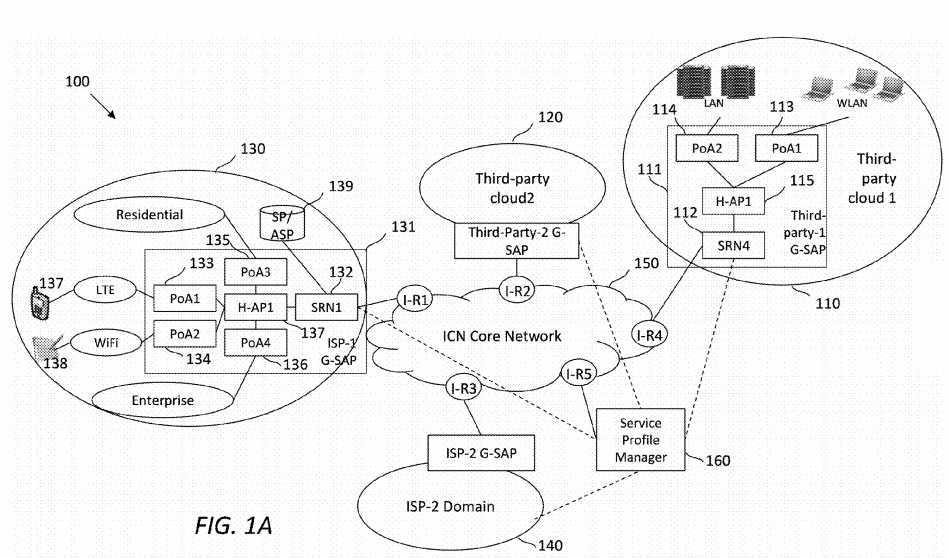
An ISP service domain may belong to an ISP, such as AT&T, COMCAST, and SPRINT. The ISP service domain may provide wired broadband connectivity, e.g., via residential or enterprise networks, and/or radio access connectivity, e.g., via WiFi, long term evolution (LTE), third generation (3G), Worldwide Interoperability for Microwave Access (WiMAX), and other wireless technologies. For example, the ISP service domain?130?may provide UE?137?(shown as a cell phone) with LTE connectivity and provide UE?138?(shown as a tablet) with WiFi connectivity.
Services within a domain may be centralized or decentralized, and may be accessed through a generic service access point (G-SAP) platform. Hence, an ICN-based SCN may be considered a network of G-SAPs overlaid on an ICN transport. G-SAPs may be utilized by various types of service domains, such as ISPs or third-party service domains. For example, a G-SAP?111?may reside in the third-party service domain?110, while a G-SAP?131?may reside in the ISP service domain?130. This framework may be generic enough to support services known today and also future services.
A service producer or a service consumer may be a device with one or more Layer 2 (L2) interfaces of the Open Systems Interconnection (OSI) model. In the framework?100, a G-SAP may support L2 agnostic seamless service mobility while providing adaptive and context-aware service resolution for producers and consumers (end-to-end). A G-SAP may be a collection of service-aware nodes equipped with a SAL. For example, the G-SAP?111?may comprise an SRN?112, a point-of-attachment (PoA)?113, a PoA?114, and a heterogeneous access point (H-AP)?115. The H-AP?115?may handle the mobility of a service producer or consumer. For another example, the G-SAP?131?may comprise an SRN?132, four PoAs133-136, and an H-AP?137. The H-AP?115?or?137?may handle the mobility of a service producer or consumer. Some or all of the G-SAPs and interior routers (I-Rs) may be managed by a service profile manager (SPM)?160, which may be a centralized network device for network-wide management.
The SRN?132?may be coupled or connected to a service provider (SP) or ASP?139. Further, UEs in a residential or enterprise network may communicate with SRNs, such as the SRN?132, via a user-network-interface (UNI) based application programming interface (API). On the other hand, an SRN, such as the SRN?132, may communicate with other SRNs, service controllers, or the SPM?160?via a network-network-interface (NNI) based API.
In the framework?100, some or all network routers may support features such as name-based routing, in-network caching and computing, and content level security semantics. For example, a SAL overlaid on ICN may be incorporated to support SCN, which may span hosts and the network. In the framework?100, a service-aware router (e.g., gateway), which may be referred to herein as a service routing node (SRN), may help meet user requirements in collaboration with other SRNs. For example, an SRN?112?located in the domain?110?and an SRN?132?located in the domain?130?may interact I-Rs located with the ICN core network?150?for their respective domain, as shown in?FIG. 1A. From the perspective of a service producer, an SRN may be the globally known locator of the service published locally. From the perspective of a service consumer, the SRN may be the gateway to resolve local services and other services.
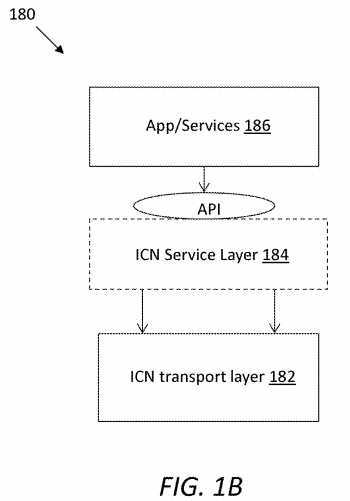
As mentioned above, devices in a network may be virtualized via ICN-based SCN as a service engine.?FIG. 1B?illustrates an embodiment of a simplified architecture?180, which may comprise an ICN transport layer?182, an ICN service layer (ICN-SL)184, and applications or services?186. The ICN-SL?184?may be a generic layer that may be used as a SAL on the user end or a SAP on the network end. For example, the ICN-SL?184?may be built over the ICN transport layer?182, which may be included in an ICN router that acts as a SAP. The ICN-SL?184?may have functionalities for service management, such as transport-level services, service publish, service discovery, service resolution, service orchestration and composition, and context-aware management. The ICN-SL?184?may also handle service-level routing decisions, which may be a special process of context-aware management and service orchestration. Moreover, the ICN-SL?184?may communicate with the applications or services?186?via an API.
Components of the framework?100?are described in more details next.?FIG. 2?illustrates an embodiment of an SRN?200, which may be used in the framework?100, e.g., implemented as the same as or similar to SRNs?112?and?132. The SRN?200may be a service gateway that may serve as a resolution point for various kinds of services. Therefore, the SRN?200?may serve multiple functions such as process context analysis, service orchestration, service discovery, service routing management, and service publishing.
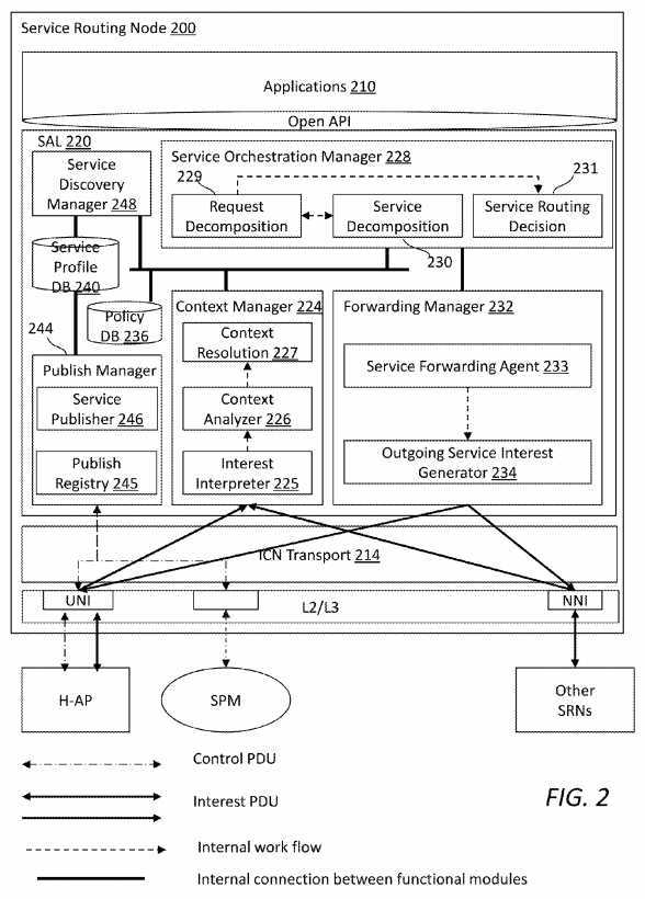
The SRN?200?may process user requests considering their contextual requirements supplied by an application. The SRN200?may also use SRN service logic processing capability to carry out service functions such as context analysis, service orchestration, service discovery, and service forwarding management. Further, the SRN?200?may serve as the gateway for service producers to assist with service management functions such as service publish, service announcement, routing and resolution. In addition, the SRN?200?may coordinate with PoA and H-AP to aid service producer mobility.
The SRN?200?may comprise applications?210?and a SAL?220?which may separate service logical control functions from an ICN forwarding plane. An open API?212?may be used between the applications?210?and the SAL?220. Further, an ICN transport layer?214?may be used for the SAL?220?to communicate with other network devices, such as an H-AP, a SPM, and other SRNs. The SAL?220?may comprise various modules or units including a context manager?224, a service orchestration manager?228, a service forwarding manager?232, a policy database (DB)?236, a service profile DB?240, a publish manager?244, and a service discover manager?248.
The context manager?224?may be configured to manage context-aware service resolution, and may comprise components including an interest interpreter?225, a context analyzer?226, and a context resolution module?227. The interest interpreter225?may interpret incoming interest, and retrieve a context part from the interest. The context part may be a device type, network access provider type, mobility context, environment context, etc. The context analyzer?226?may collect context information from an original service interest packet and translate the collected context information into a standard service description format. By querying the policy DB?236?and invoking the service discovery manager?248, the context resolution module?227?may resolve context-oriented service description(s) to a corresponding actionable service identifier(s) (ID), which may then be updated in the policy DB?236, if necessary.
The service orchestration manager?228?may be configured to create a service logic operation graph, which may guide service forwarding. The service orchestration manager?228?may carry out various functions (represented by functional boxes in?FIG. 2). In a request decomposition function?229, the service orchestration manager?228?may decompose an initial service request into a number of services, and then invoke the service discover manager?248?to determine if any of these services have local instantiation, by querying the service profile DB?240. If a service is determined to be locally resolvable, the service orchestration manager?228?may invoke a service decomposition function?230. By looking up the service profile DB?240?and policy DB?236, the service decomposition function?230?may further decompose a service into multiple tasks. The tasks may be processed by servers in the same domain or different domains. By performing a function of service routing decision?231, the service orchestration manager?228?may create an overall service logic graph, which may present relationships between different services, albeit not between tasks.
The service forwarding manager?232?may be configured to process the service logic created by the service orchestration manager?228, and forward the service logic to a next hop service interest. More specifically, the service forwarding manager?232?may comprise a service forwarding agent?233?configured to process and update a service navigation vector and determine an ID of the next-hop service. The service forwarding manager?232?may further comprise an outgoing service interest generator?234?configured to generate, based on the next-hop service ID, one or more outgoing service interest packets with updated service navigation fields. A routable service prefix may be associated with the service interest to conduct name-based routing.
The policy DB?236?may be configured to store policies for context translation as well as mapping relationships between context-oriented service description and corresponding service ID. By invoking the service discovery manager?248, mapping relationship entries can be committed to the policy DB?236?by the context resolution module?227?as new resolutions results. The service profile DB?240?may be configured to locally store service information, such as service ID, service description, and mapping to resolution point such as local service location or remote resolution domain information. The remote service resolution point information may be added by the publish manager?244.
The publish manager?244?may be configured to handle service publishing management function from users. The publish manager?244?may comprise a publish registry?245?and a service publisher?246. The publish registry?245?may manage a new service registration from a service producing entity such as an end user, an in-network service function, or a third-party application service provider (ASP). In an embodiment, the publish registry?245?may update the service profile DB?240?to register a new service publish action from a service producer. In other words, the publish action of the new service may be updated in the SRN?200.
Note that management of registration may include name space delegation based on whether the service has a local or global scope, interacting with service producers to enable or disable service availability, etc. The service publisher?246?may publish a newly available service to a service profile manager, such as the service profile manager?160. The service profile manager may notify the service publisher?246?about the resolution points of producers who may support the same service. In turn, the service publisher?246?may update the service profile DB?240.
In addition, the service discovery manager?248?may be configured to process a service description, and return a corresponding service ID as well as the information to resolve a service. A person of ordinary skill in the art will recognize that the functions, modules, or units disclosed herein may be implemented via any suitable approach, e.g., via hardware or a combination of hardware and software.
FIG. 3?illustrates an embodiment of a service request processing method?300, which may process a service request and resolve a requested service name to a specific domain based on a user‘s contextual requirements. This procedure may occur at the ICN-enabled gateway (SRN) of a domain, where a SAL may be overlaid with the ICN transport layer on the gateway, e.g., as shown in?FIG. 1B. To differentiate from content interest, the term "request" may be used herein to indicate an initial service interest sent from a consumer‘s application. A request may include, but not limited to, a service ID and context metadata from the consumer from which it was sent.
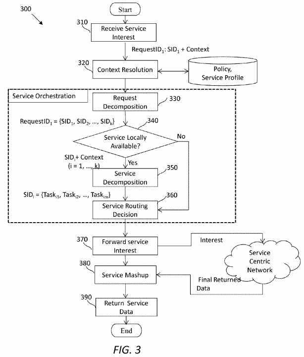
The method?300?may start in step?310, in which an SRN in a G-SAP platform (e.g., the SRN?200) at a service domain may receive a service interest. The service interest may comprise a service request identifiable via a request ID (denoted as RequestID1) and context. In step?320, the SRN may process context information associated with the initial interest, by checking it against a service profile manager, e.g., in the service profile DB?240, and relevant policies, e.g., in the policy DB236. In step?330, the original service request may be decomposed into a number of different services. For example, the request identifiable via RequestID1?may be decomposed into services identifiable via service IDs denoted as SIDs SID1, SID2, SIDk, where k is an integer greater than one. Note that since service IDs may distinctly identify services, a service may be represented simply by its service ID (SID).
In step?340, the SRN may look up the service profile DB to determine if any of these services are available locally. If the condition of the step?340?is met, the method?300?may proceed to step?350; otherwise, the method?300?may proceed to step?360.
In step?350, a service has a local entry point, namely, it may be available in the same domain. Thus, the SRN may decompose the service into multiple service tasks (in short as tasks). For example, a service identifiable via SID1?may be decomposed into tasks identifiable via task IDs denoted as Taski1, Taski2, Taskim,?where i and m are integers and i is no greater than k. If a service does not have an entry point locally, according to step?340, the corresponding service ID may be kept for constructing a service logic graph without further decomposition.
When the SRN has performed decomposition at the request level and/or service level, in step?360, the SRN may run a service routing decision process to generate a logic service graph. Note that, in the disclosed SCN framework, service orchestration may include both service decomposition and routing management. After finishing the service orchestration, in step?370, the SRN may forward or push the service interest dictated by the service logic graph down to an ICN transport layer. In step?380, the SRN may combine results from multiple service producers to generate a response using returned data from the network. In step?390, the SRN may return data back to the customer or may return a handle to retrieve the data.
To further clarify functioning of an SRN,?FIG. 4?illustrates an embodiment of a work flow?400?showing message exchanges among functional modules or units within the SRN?200?and between the SRN and the SPM?160. In use, a service request message comprising an interest packet may be received comprising context metadata or contextual information. The contextual information may be relevant to the UE or an access network connected to the UE. The interest interpreter?225may send the context metadata to the context analyzer?226, which in turn may query or look up policies stored in the policy DB?236. The policy DB?236?may return an acknowledgement to the context analyzer?226, which may then send a context-aware standard service description to the context resolution module?227. The context resolution module?227?may then query the policy DB?236?again, which returns with another acknowledgement.
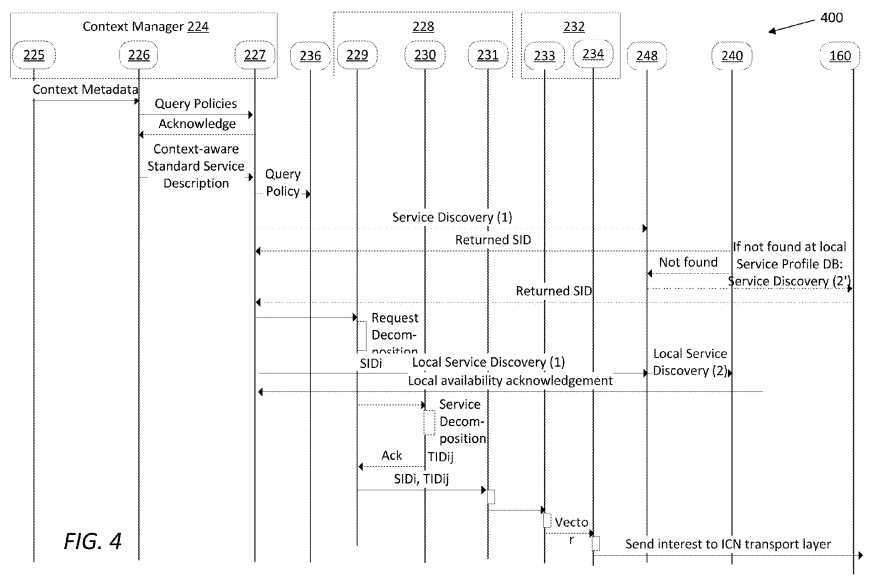
The context resolution module?227?may translate the contextual information in the interest packet into a service description written in a service description language. Further, the context resolution module?227?may send the description to the service discovery manager?248?and then to the service profile DB?240, in which the service description may be mapped to one or more corresponding SIDs. After service discovery, the service profile DB?240?may return the SID to the context resolution module?227. If no SID corresponding to the service description is found in the service profile DB?240, the SPM?160?may be contacted for further service discovery. After determining a SID, the SPM?160?may return the SID to the context resolution module?227.
Next, the service request may be decomposed into one or more services by the request decomposition function?229. A service in the decomposed services may be discovered again by the service discovery manager?248?using the service profile DB?240. If a service is available locally (in a service domain comprising the SRN?200), an acknowledgement may be returned to the request decomposition function?229.
For a service that has at least one instance locally available, the service may be further decomposed into a plurality of tasks corresponding to service instances. After full decomposition, a service logic graph and its corresponding service navigation vector may be generated by the service forwarding agent?233. The outgoing service interest generator?234?may pack the service logic graph and/or the service navigation vector into an outgoing interest, which may be sent to an ICN layer of the SRN?200.
FIG. 5?illustrates an embodiment of an H-AP?500?which is a component for mobility management in an ICN-based SCN framework (e.g., the framework?100). Within the SCN framework, the H-AP?500?may be the gateway of an ICN-enabled ISP. The H-AP?500?may be used when users or applications are multi-homed. The H-AP?500?may comprise a service access controller (SAC)?510?which may serve as a service access anchor and a mobility controller (MC)?520?which may serve as a network access anchor. A service engine?530?and an ICN layer?540?sitting beneath the SAC?510?and the MC520?may be configured to process service-level forwarding.
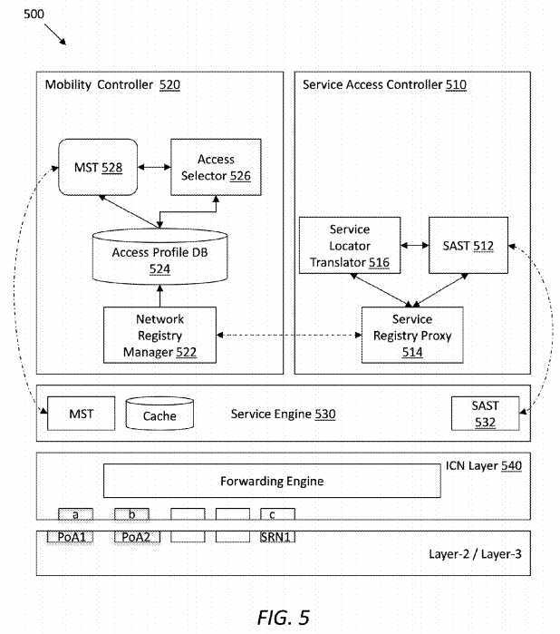
The SAC?510?may maintain a service access strategy table (SAST)?512?configured to support service indirection. The SAC510?may further comprise a service registry proxy?514?configured to processes a service publishing message from a UE or a SAST update message from a network registry manager?522?residing in the MC?520. The service publishing message may carry information such as service ID, service access prefix, service publish priority, service producer, service attributes such as TTL, access control policies. The SAC?510?may further comprise a service locator translator?516?in the control plane configured to send the service publishing message to an SRN (e.g., the SRN?200) for further processing.
More specifically, the SAST?512?may be a table reflecting service access status for service indirection references. In an example embodiment, the SAST?512?may have five fields:
<Service Identity, Service Access Context, Service Status, Priority, time to live (TTL)>, as shown in Table 1. Service identity may be a persistent name of a service, such as a SID. Service access context may show resolution point information of the service, such as associated PoAs and UEs. Service status may indicate a status of the service, such as being accessible (indicated by Y) or inaccessible (indicated by N). Priority, with exemplary values 1-3 in Table 1, may indicate a priority of the service access context, as determined by the user or the device. Finally, TTL, with exemplary values denoted as t1-t4?in Table 1, may indicate a belief time of the service.
TABLE 1? | ||||
| ? | ||||
An exemplary SAST? | ||||
| ? | ? | Access? | ? | ? |
Service Identity? | Service Access Context? | Status? | Priority? | TTL? |
| ? | ||||
<SID1> | <PoA1>: <UE1>? | Y? | 1? | t1 |
| ? | <PoA1>: <UE2>? | Y? | 2? | t2 |
| ? | <PoA2>: <UE1>? | N? | 1? | t3 |
| ? | <PoA2>: <UE2>? | Y? | 3? | t4 |
| ? | ||||
Referring back to?FIG. 5, in an embodiment, when a new service is published from a UE, a corresponding publishing message may first arrive at the SAC?510. The service registry proxy?514?may process the publishing message and send it to the service locator translator?516. The service locator translator?516?may add a new entry to the SAST. The service locator translator?516?may then update the service publishing message with a prefix of the H-AP?500. The service locator translator?516?may send a response to the service registry proxy?514, which in turn may notify an SRN that this new service is available from the H-AP?500.
The MC?520?may play the role of a network access anchor point and may provide mobility management for UEs based on network attachment properties. In other words, the MC?520?may handle interest and data between PoAs (e.g., between PoAs?133?and?134) during hand offs. In an embodiment, the MC?520?may comprise a Network registry manager?522, an access profile DB?524, an access selector?526, and a mobility strategy table (MST)?528, arranged as shown in?FIG. 5.
The network registry manager?522?may take network attachment requests from PoAs, input registration information into the access profile DB?524, and update the MST?528. The access profile DB?524?may store detailed information about UE‘s network connectivity registration. The access selector?526?may be a smart module to update a corresponding priority entry in the MST?528, based on policies. The MST?528?may be a table configured to store network access context information for mobility of user devices. The MST?528?may be constructed when a device registers the network connectivity. The MST?528may help to direct interests to a proper access network in case of a service producer, by avoiding unnecessary multicasting.
Table 2 shows exemplary fields of the MST?528, which may comprise two fields: access context states and priority information. Access context may indicate a network connectivity prefix, such as <PoA1>:<UE1>. Priority information may indicate the priority of forwarding. Note that a value of the priority may be dynamically updated by the access selector?526.
TABLE 2? | |||
| ? | |||
An exemplary MST in an H-AP | |||
| ? | Access Context States? | Priority? | |
| ? | ? | ||
| ? | <PoA1>: <UE1>? | 1? | ? |
| ? | <PoA2>: <UE1>? | 2? | ? |
| ? | <PoA1>: <UE2>? | 1? | ? |
| ? | <PoA2>: <UE2>? | 1? | ? |
| ? | ? | ||
Referring back to?FIG. 5, the service engine?530?may comprise a SAST?532?and may conduct interest and data forwarding processing as required by service applications, which may include functions resulting from the MST?528?and/or the SAST512. During the hand off process, interests and/or data may be cached at the service engine?530. In addition, the ICN layer540?may facilitate communication between the upper layers and lower layers (e.g., layer?2?and layer?3).
FIG. 6?illustrates an embodiment of a PoA?600, which may be implemented in an ICN-based SCN framework (e.g., the framework?100). The PoA?600?may be an ICN-enabled access network gateway, which may provide connectivity to a UE and support control plane functions to aid service mobility between multiple devices. The PoA?600?may comprise a Mobility Proxy Agent (MPA)?610, which may play a role as a network attachment proxy that is in charge of network access registration for UEs. As shown in?FIG. 6, the MPA?610?may comprise a network registry proxy?612, an access profile DB614, an access selector?616, and an MST?618. It can be seen that the MPA?610?may have similar system view as an MC (e.g., the MC?520) in an H-AP (e.g., the H-AP?500). In the interest of conciseness, further descriptions will focus on aspects that are different or not yet covered. The same principle applies to other drawings described herein.
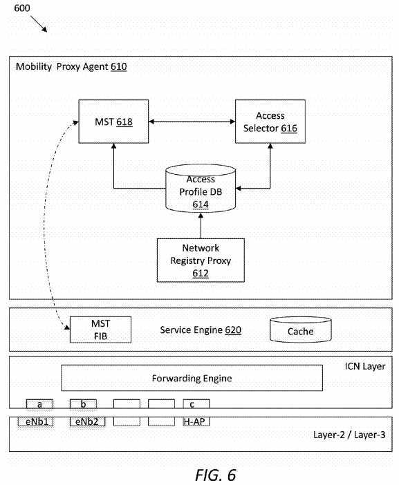
In use, the MPA?610?may have information about a prior registration of the PoA?600?in an H-AP. Thus, when a UE sends a request for network registration, the PoA?600?may respond to the UE with an H-AP prefix and also send a notification to the H-AP about a connection request from the UE. The network registration request message may carry information such as a device ID for the UE and the corresponding TTL.
Table 3 shows exemplary fields of the MST?618, which may be similar to the exemplary MST?528?shown in Table 2. Access context may indicate a network connectivity prefix, such as <UE1>, and priority information may indicate the priority of forwarding.
TABLE 3? | |||
| ? | |||
An exemplary MST in a PoA? | |||
| ? | Access Context States? | Priority? | |
| ? | ? | ||
| ? | <UE1>? | 1? | ? |
| ? | <UE2>? | 2? | ? |
| ? | ? | ||
Referring back to?FIG. 6, a service engine?620?residing in the PoA?600?may play the same or a similar role as the service engine?530?in the H-AP?500. One difference is that the service engine?620?may not have a SAST (note that the service engine?530?has a SAST?532), as the PoA?600?may not contain a SAC module.
FIG. 7?illustrates an embodiment of an ICN-enabled UE?700, which may be implemented in an ICN-based SCN framework (e.g., the framework?100). UEs may refer to any applicable ICN-enabled devices, such as smartphone, tablet, laptop, desktop, and other types of devices with one or more radio access interfaces such as LTE, WiFi, and WiMAX. In addition to being service consumers, UEs themselves can also be service producers. The UE?700?may comprise a service access agent (SAA)?710?and a mobility agent (MA)?720?over an ICN layer?730. The MA?720?may take responsibility of network connectivity registration, and the SAA?710?may handle service-relevant functions. The MA?720?may also interact with the SAA?710?on the control level to help with service management functions. The UE?700?may further comprise one or more of applications?740, contents?742, and/or context sensing module?744. The applications?740?may communicate with the SAA710?via a standard interface, such as Open API?746. The Open API?746?may provide service-level management transport functions, such as multiplexing, de-multiplexing, quality of service (QoS), flow control, and so forth.
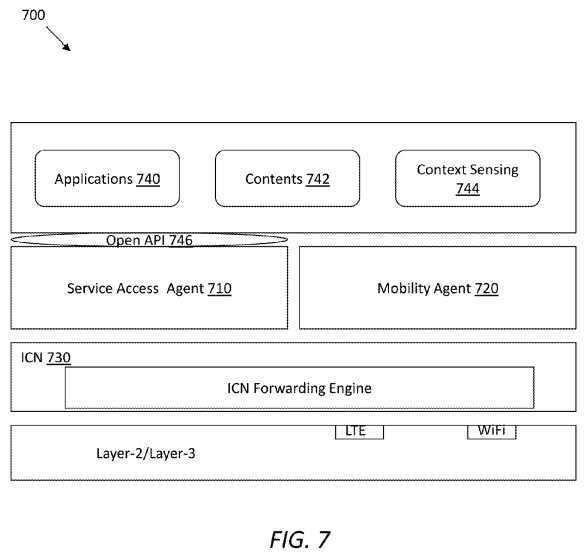
FIG. 8?illustrates an embodiment of a SPM?800, which may be implemented in an ICN-based SCN framework (e.g., the framework?100). The SPM?800?may be a logical entity that provides centralized management for SRNs. The SPM?800?may facilitate global service publishing, service discovery, service resolution, and other functionalities. Arranged as shown in?FIG. 8, the SPM?800?may comprise its functional blocks including a service registration module?810, a service discovery module820, a service resolution module?830?and a service directory?840.
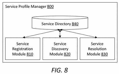
The service registration module?810?may process service publish messages from SRNs and update the service directory840. The service discovery module?820?may receive a service description from SRNs or UE applications, and may return relevant service IDs after looking up the service directory?840. The service resolution module?830?may resolve the service IDs into globally known locator information for SRNs. The service directory?840?may be implemented as a global service profile database, which may include, for a service, at least a service ID, global locator for the service, a service description, and TTL. The service directory?840?may be represented as an extensible markup language (XML)-based schema.
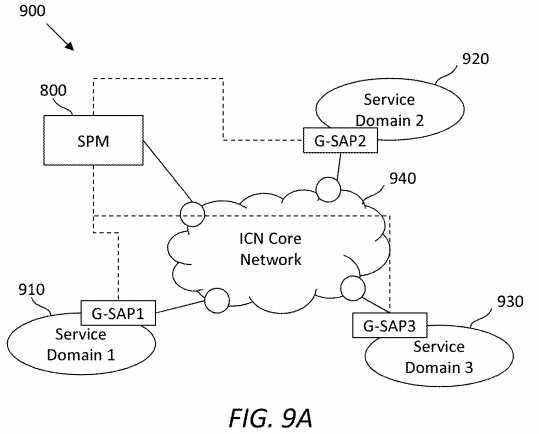
The SPM?800?may be deployed to manage multiple domains, or alternatively on a per-domain basis (i.e., with multiple SPMs for multiple domains).?FIG. 9A?illustrates an embodiment of an ICN-based SCN framework?900, in which the SPM800?is configured to manage a plurality of service domains?910,?920, and?930. Recall that each of the service domains?910,920, and?930?may have a G-SAP configured to communicate with an ICN core network?940?via edge nodes.
FIG. 9B?illustrates an embodiment of a network framework?950, which may enable end-to-end edge cloud services. The control and physical elements enabling an edge-cloud framework are shown along with open-APIs between a user?952, an ISP?954, and an ASP?956?through an ICN-SP?957. The implementation of the open-APIs between network devices may vary. For example, an SAL in the user?952?may communicate with an SAP in an SRN?958?via a service user-network-interface (S-UNI) API. The SRN?958?may communicate with another SRN?960?via a service network-network-interface (S-NNI) API. Further, the SRN?958?may further communicate with a service controller (SC)?962?via a SC-SRN API.
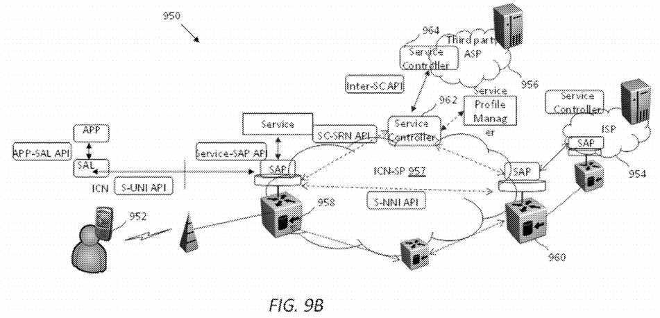
The SC?962?may be a logically centralized entity interfacing with other SCs, such as an SC?964, through inter-SC API in third party domains to accept service management requests such as provisioning resources, and conveying policy management instructions to service instances. Inter-SC API requests for service management such as managing service resources may be handled in the ICN-SP?957?through a SC-SRN API to convey service instructions to SAP instances in SRNs. The SCs in multiple domains may interact to populate services available in each other‘s domain for local use, and these interactions could be policy driven.
As described above, the ICN-SL structure on the user end and network end are similar but may have different functions. FIG. 9C?illustrates an embodiment of functions offered by an SAL?970?on the user end (e.g., the user?952) and an SAP?980on the network end (e.g., the SRN?958). The SAL and SAP may facilitate contextual interaction between the users and ICN-SP. Part of the functions have been described above, thus further discussion will focus on aspects that are not yet covered.
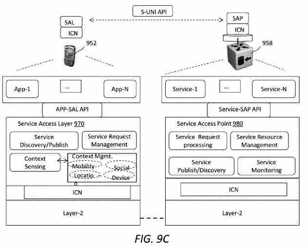
On the user or end host end, the SAL?970?may handle service layer control, forwarding, and contextual functions. Control functions may include the ability to discover, publish, and request services from the network over the S-UNI API. Applications may leverage the SAL?970?through an application (APP)-SAL API. When applications request context support, the SAL?970?may interact with its context sensing functions to obtain real time state of the context to be included in the service request. Various contextual information such as mobility context, location context, social context, and device context may be used. For example, location context may imply obtaining real-time location information. In addition, forwarding functions may include the mux/demux of application requests and those related to adapting service flows to varying user context such as mobility.
On the network end, the SRN?958?may host ASP or ISP services over the SAP?980. Services may access the SAP?980through a service-SAP API. The Service-SAP API may provide support functions for ASP service to meet its service objectives, such as service discovery to augment its own service, real time statistics of service, storage graphs and resource utilization, and executing multi-hop service processing logic involving its own or other services distributed in ICN-SP. Some service SRNs without the S-UNI may also reside in the ICN core network. These nodes may also act as gateways to services hosted in data centers or third party ASP domains. Further, the SRN?958?may interact with the ICN core to obtain global topology information and help services to orchestrate service routing logic while processing user requests. Inter-domain SRN interaction among ISPs and ASPs can be realized to enable multi-domain service composition and routing logic.
According to an ICN naming scheme, a service name may be defined in the form of <P>: <I>: <D>, wherein P stands for "Principal", I stands for "Identity", and D stands for "Domain". This naming scheme is described in U.S. patent application Ser. No. 13/729,897 to X. Zhang, et al. and entitled "Principal-Identity-Domain Based Naming Scheme For Information Centric Networks," which is incorporated herein as if reproduced in its entirety.
P may be used for security purposes. For example, P can be a hash function of producer‘s public key, e.g., presented as Hash_{PubKeyAlice}, where Alice is a random name representing a user. I may be a hierarchical structure or a flat ID to represent a service name for service discovery and service late-binding with a locator. For example, if Alice publishes a personal album access service, I could be presented as </Alice/Personal_Album/>. D may be the name of a domain‘s entity that provides identity resolution service, e.g., the name of a gateway that provides a resolution service to resolve a service identity to a globally known locator identity. For example, if Alice publishes a service from a network belonging to ATT, then D may be presented as /ATT/SRS/, where SRS stands for service resolution system. Now the whole name for Alice‘s personal album access service can be represented in <P:I:D> form: <Hash_{PubKeyAlice}>:</Alice/Personal_Album>: </ATT/SRS/>.
When a new service is published, an SRN in the service domain may notify a SRS about a global locator for the service. Thereby, when a consumer resolves a service, the service may be resolved to have the appropriate D. Recall that if a SPM is deployed in a per-domain manner, identification of the SPM may be used as the D in the <P:I:D> name scheme.
An SRN (e.g., the SRN?200) may act as a proxy for a user application to process a request and generate a response for the request. Packets sent between UE terminals and local SRNs may comprise SAL UNI packet data units (PDUs), while packets sent between SRNs may be considered SAL NNI packets.
FIG. 10A?illustrates an embodiment of a SAL UNI interest packet?1000, which may be sent from a UE to an SRN. A type field indicates the packet is an interest packet. A service ID may identify the service requested by the consumer. A nonce may be a random number appended to the service ID to form a unique Request ID. Contextual information of the consumer may be stored as context metadata in a SAL header of the interest packet?1000. Context metadata may comprise device context, mobility context, environment context, network context, consumer social context, etc.
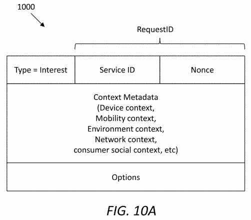
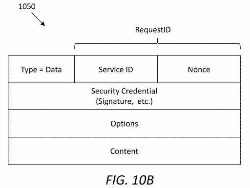
FIG. 10B?illustrates an embodiment of a SAL UNI data packet?1050, which may be sent from an SRN to a UE as a response to the interest packet?1000. A type field indicates the packet is a data packet, e.g., returned to the UE. A service ID may identify the service requested by the consumer. A nonce may be a random number appended to the service ID to form a unique Request ID. The SAL header of the data packet?1050?may include a service producer‘s signature and related security credential information.
FIG. 11A?illustrates an embodiment of a SAL NNI interest packet?1100, which may be sent from a first SRN to a second SRN. A type field indicates the packet?1100?is an interest packet. A service ID and a nonce field may be the same as a SAL UNI interest packet (e.g., the packet?1000), in order to indicate that the NNI interest is generated for the same Request ID. In the interest packet?1100, service navigation fields may provide service logic forwarding instructions, which will be further described later. The service logic graph may store overall service logic information, which is derived from service orchestration. The service context metadata may be filtered from the consumer‘s context information, and may be used for decomposition of a service into tasks.
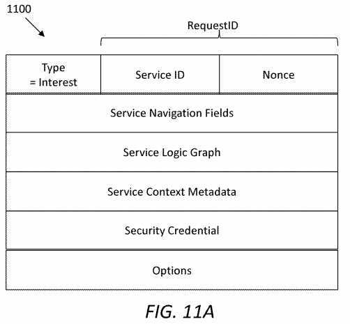
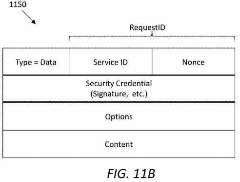
FIG. 11B?illustrates an embodiment of a SAL NNI data packet?1150, which may be sent from a second SRN to a first SRN. A type field indicates the packet?1150?is a data packet. A service ID and a nonce field may be the same as a SAL UNI data packet (e.g., the packet?1050), in order to indicate that the NNI interest is generated for the same Request ID. The SAL header of the data packet?1150?may include a service producer‘s signature and related security credential information.
When it comes to the mobility management of service application and data, from a consumer‘s perspective, it may be desired for a service to be reachable from anywhere. Therefore, one of the motivations in this disclosure is to introduce a new definition: Network-As-A-Datacenter, by utilizing in-network caching, computing, and service routing management to deliver services and enrich users‘ experience. Applications may migrate to any authorized server(s) located at different places, according to the users‘ requests, content delivery statistics, and/or network resource allocation. The applications may be hosted by content routers or a regular pool of servers. As an example, suppose that a service domain only provides a video downloading service but doesn‘t provide a transcoding service. Further suppose that there is a large number of service requests arriving at this service domain with both video downloading and video transcoding interest. In this case, the ICN-based SCN framework may migrate, from elsewhere, an authorized transcoding service as a localized service, thereby reducing transition latency between two services.
ICN may use name-based routing to decouple content identity from its actual location, which may allow for efficient delivery of static content published in advance. An objective of this disclosure is to generate contextualized content using the service delivery capability of an ICN-based SCN framework. As mentioned previously, a two-level service decomposition approach may be used to adapt the requested service considering user‘s context. Further, a service routing mechanism may be designed to navigate services as a result of decomposition.
For consumer request decomposition, a SCN framework may process a service interest sent from a consumer taking into account various contextual factors such as affiliation, location, mobility context, device context, and personal or social context of the consumer. These contextual properties may be interpreted and broken into multiple services.
Once an original service request is decomposed into multiple services, each individual service may be further decomposed based on several factors such as network attachment status or the server‘s status and the consumer‘s contextual information. Note that the server‘s status may refer to a bandwidth and/or a throughput at the server. A service may comprise a plurality of instances, which are distributed at multiple servers but provide the same service. Therefore, an interest to a particular service may be decomposed into multiple tasks.
FIG. 12?illustrates an embodiment of a two-level service request decomposition scheme?1200, which is presented as a tree-like structure. Note that a request ID (denoted as RID1) may be considered equivalent to a service identity that a consumer originally requests, with a nonce, to uniquely represent the original service request from the consumer. A service ID (denoted as SID1, SID2, SIDk,) may be a unique name that indicates a particular service. Further, a task ID (denoted as TID11?to TIDkk) may uniquely indicate a service instance that is decomposed from an individual service. A task ID may be considered equivalent to a specific service ID with a nonce, and task IDs may be used by differentiate tasks processing the same service. As shown in?FIG. 12, on a first level a request is decomposed into multiple services, and on a second level, each of some or all of the services is decomposed into multiple tasks.
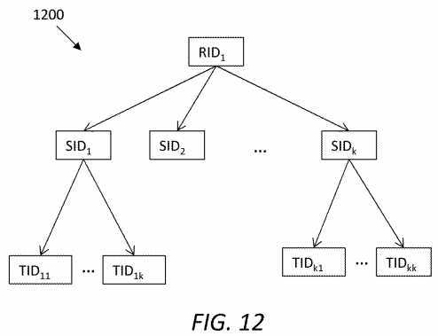
FIG. 13?illustrates an embodiment of a service orchestration scheme?1300, in which SRN1, SRN2?and SRN3?may belong to three different service domains interconnecting each other. Assume that each of the domains has a pool of servers, and that a consumer resides in the same domain as SRN1. Servers denoted as Server11?and Server12?are located in the same domain with SRN1?and may both perform SID1. Server21?and Server22?are located in the same domain with SRN2, wherein Server21?may perform SID1?and Server22?may perform SID1?and SID2?Further, Server31?and Server32?are located in the same domain with SRN3?and may both perform SID3.
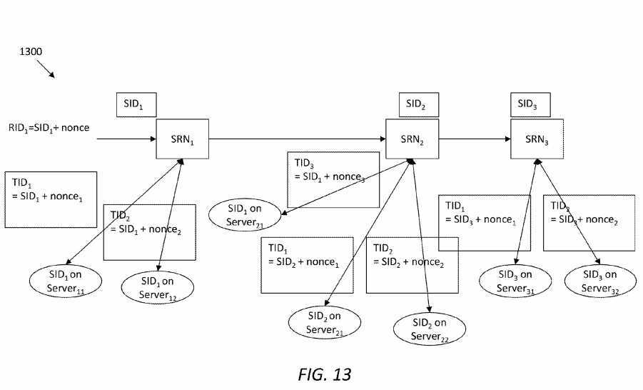
As shown in?FIG. 13, SRN1?may decompose an original RID1?into three specific services identifiable via SID1, SID2, and SID3. Further, by looking up a local Service Profile DB (e.g., the service profile DB?240), SRN1?may find that SID1?is accessible both locally and from SRN2. Accordingly, SRN1?may further decompose SID1?into three tasks identifiable via TID1, TID2, and TID3, where TID3?is implemented through SRN2. In the same manner, SID2?and SID3?may be further decomposed into two tasks once the service interests arrive at SRN2?and SRN3, respectively. In the scheme?1300, the SRN1, SRN2?and SRN3?may form a SCN for RID1. However, the SIDs may need to be properly navigated using service routing management, which will be described next.
Recall that in the two-level service decomposition (e.g., scheme?1200?and?1300), a general service request sent by a consumer may be decomposed into two or more specific services collaborating together to fulfill the consumer‘s request under his/her context. Moreover, each individual service may be further decomposed into multiple tasks, where each task may process part of the service. How to manage the internal service logic for the consumer‘s original request and guarantee the proper sequence of service processing may be a significant procedure of service orchestration, thus a service-level routing management mechanism is disclosed herein to achieve this goal.
Note that a task may be considered an instance of a particular service. In other words, if a service is able to be decomposed into multiple tasks by an SRN, the SRN may function as a master node which divides the work to multiple servers. The servers may be considered as worker nodes, e.g., in a MapReduce (a programming model) scenario. Therefore, the tasks may be processed in parallel, and there may be no data transmission between the servers. In the service-level routing management, we consider services with different service IDs which are derived after the first level decomposition (i.e. request to services). Note that these services may be processed in a sequential, parallel, or hybrid manner. Similar to today‘s routing management, a control plane and a data plane may be used on the service level.
A control plane for service routing is described next. Recall that the decomposition process breaks an original consumer‘s request (identifiable by a request ID) into discrete services, which may be independent from each other. Therefore, an internal logic may be created to link these services to adapt changes to consumer‘s contexts.
A service routing control plane may be in charge of creating service level logic graph and construct a service navigation vector. The service navigation vector may comprise or be represented by service navigation fields. Both the service logic graph and the service navigation vector may be carried in the header of a SAL NNI PDU.
A service logic graph may be created by considering several policies that are based on service semantics and contextual properties. Using service semantics or properties, services can be divided into multiple categories or types, including but not limited to: (1) content delivery services (e.g., downloading and/or uploading of video, audio, image, and/or document, etc.); (2) real-time service (e.g., voice over IP (VoIP), video conference, video streaming, etc.); (3) process-oriented services, which may be application for particular data processing (e.g., transcoding, encryption services, load balancing, etc.); and (4) gateway services (e.g., firewall, virtual private network (VPN)).
In operation, an initial request from a consumer application may be decomposed into multiple services according to relevant contextual information carried by an interest packet in the request. The execution of these services may be based on the types of these services. For example, a service request may be decomposed into two services: a content delivery service and a load balance service. Further, the load balance service may not be directly requested from the application, but rather is a context-aware service to improve the content delivery service. In this case, a service logic between the two services is series. More examples are given below to explain the service logic graph.
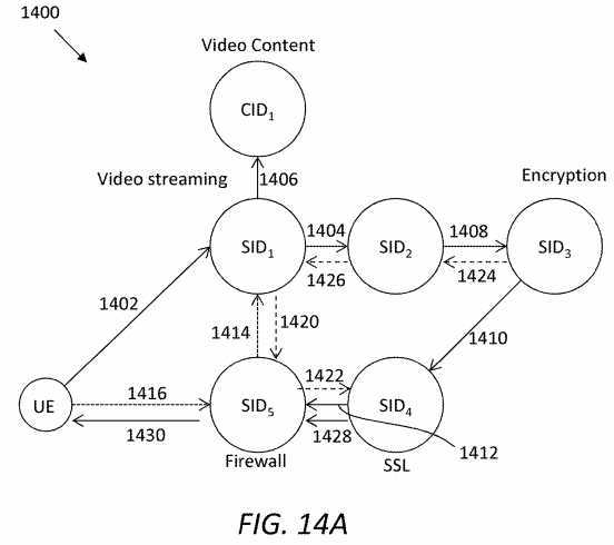
A service logic graph may present an internal relationship between individual services after decomposition. The service logic graph may show an order in which services need to be invoked to satisfy the original request.?FIG. 14A?illustrates an embodiment of a service logic graph?1400, which is created based on service semantics and assumes a user scenario of video streaming services. Suppose a consumer uses a mobile device with a low resolution screen, and the consumer uses public WiFi (sometimes slow) as network connectivity. By interpreting the context of the consumer, an SRN may determine that, besides the video streaming request, the consumer needs more process-oriented services (e.g., transcoding and encryption) and gateway services (firewall services) provided at the SRN.
In?FIG. 14A, SID5?may be a service that can be directly accessed at the SRN in the UE‘s domain, while other services may reside in the same domain as SID5?or at different places. These five services may be processed in series, which is presented herein in the form of SID1+SID2+SID3+SID4+SID5. SID1?may retrieve video content denoted as CID1?before reaching SID2. In?FIG. 14A, arrows?1402-1416?indicate interest paths and arrows?1420-1430?indicate data paths. Further, arrows?1402-1412?and?1428-1430?indicate the service level logic, and arrows?1414-1416?and?1420-1426?indicate actual paths taken during ICN transport, which may be different from the service-level logic.
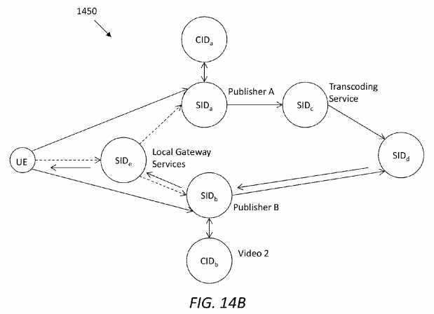
When decomposing an original service request, some individual services may not be related to each other, thus they can be processed concurrently.?FIG. 14B?illustrates another embodiment of a service logic graph?1450?reflecting this scenario. For example, a consumer may request a video editing service to join two videos from different producers or publishers (Publisher A and B). Further suppose that, by interpreting the context of the consumer, the original service request may be decomposed into five (may be any other number) individual services: {SIDa, SIDb, SIDc, SIDd, SIDe}, among which SIDaand SIDb?are independent, as they represent two different video producers, and SIDc?is a follow-up service to SIDb. Accordingly, there may be two parallel service paths before start running service editing service (SIDd). The result of service orchestration may be presented as SIDa+{SIDb, SIDE}+SIDd+SIDE, where "+" indicates series and "{,}" indicates parallel.
In order to correctly direct service forwarding according to the service logic graph, we design a service navigation vector which can be dynamically updated along the service path within a SAL header. In an embodiment, there may be five fields in the service navigation vector:
FIG. 15A?illustrates an embodiment of a service logic topology?1500, in which a request RID1 may be decomposed into services executed following the order SID0+{SID1, SID2}+SID3+SID4. Based on the topology?1500, Table 4A-4C show examples of service navigation vectors updated at a first-hop SRN, an intermediate-hop SRN and a last-hop SRN, respectively. It can be seen that the first-hop, intermediate-hop, and last-hop SRNs are configured to fulfill SID0, SID3, and SID4?respectively.
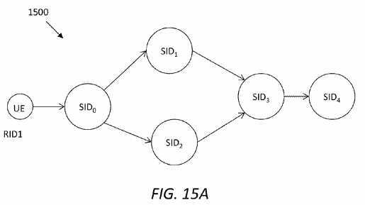
TABLE 4A? | ||||
| ? | ||||
An example of updated service navigation? | ||||
vector at a first-hop SRN? | ||||
Request? | Source? | Current? | ? | Next? |
ID? | Service ID? | Service ID? | Rule? | Service ID? |
| ? | ||||
RID1 | *? | SID0 | Parallel? | SID1, SID2 |
| ? | ||||
?
TABLE 4B? | ||||
| ? | ||||
An example of updated service navigation | ||||
vector at an intermediate-hop SRN? | ||||
Request? | Source? | Current? | ? | Next? |
ID? | Service ID? | Service ID? | Rule? | Service ID? |
| ? | ||||
RID1 | SID1,?SID2 | SID3 | Series? | SID4 |
| ? | ||||
?
TABLE 4C? | ||||
| ? | ||||
An example of updated service navigation vector at a last-hop SRN? | ||||
Request? | Source? | Current? | ? | Next? |
ID? | Service ID? | Service ID? | Rule? | Service ID? |
| ? | ||||
RID1 | SID3 | SID4 | /? | /? |
| ? | ||||
Service navigation vectors, e.g., as shown in Table 4A-4C, may offer a guide on how to forward next service(s). In particular, the field of rule may indicate how to forward next-hop services. If the rule field is set as parallel, it may indicate that the next-hop services are independent, and the corresponding interests can be forwarded at the same time; otherwise, if the rule field is set as series, it may indicate that one service is to be processed after a current service. Further, a Source Service ID field may assist the current SRN to check if previous services are completed when last-hop services are processed in parallel. For instance, in?FIG. 15A, SID3?may not begin processing until SID1?and SID2?are both completed.
FIG. 15B?illustrates an embodiment of a request routing scheme?1550, which assumes that a service logic graph?1552?is designed for a service request denoted as R1. The service logic graph?1552?comprises three services denoted as S1, S2, and S3, among which S1 needs to retrieve content denoted as C1. Note that S1, S2, and S3 may belong to a service pool, which may contain other services, such as those denoted as Sa, Sb, Sc, Sd, and Se, that are not needed to process R1. A number of SRNs are included in an ICN-based SCN network, each of which may comprise an application layer, a SAL, and an ICN layer. As shown in?FIG. 15B, an SRN?1560?may perform Sa, an SRN?1562?may perform S1, an SRN?1564?may perform Sd, an SRN?1566?may perform S2 and Sb, an SRN?1568?may perform S3 and Sc, and an SRN?1570?may perform Se.
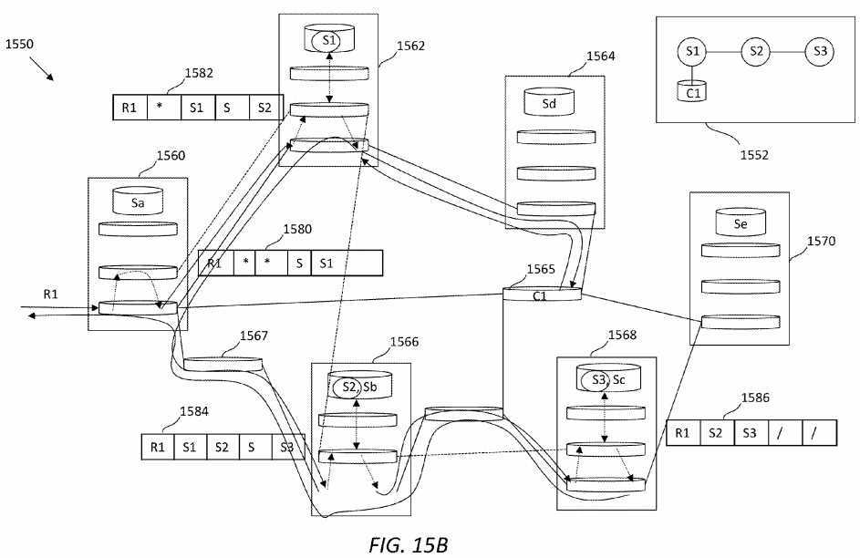
In use, the request R1 may be received by the SRN?1560. According to the service logic graph?1552, the first-hop service S1 may not be performed by the SRN?1560. Thus, a service navigation vector?1580?updated in the SRN?1560?may not need to list any current service. As described earlier, the service navigation vector?1580?may set R1 as its request ID, the rule as series, and S1 as its next service ID. The SRN?1560?forwards the request R1 to the SRN?1562, which may perform service S1 according to the service logic graph?1552. Further, the SRN?1562?may generate an updated service navigation vector1582, which may set S1 as its current service ID, series rule, and S2 as its next service ID. Next, the request may be forwarded to the SRN?1564, which may retrieve content for the request from a network node?1565.
Further, the request may be forwarded to the SRN?1566?via the SRN?1562, the SRN?1560, and a network node?1567. Note that, depending on the architecture of the ICN network, the request may take any other route to reach the SRN?1566, where S2 may be performed for the request. In addition, the SRN?1566?may generate an updated service navigation vector1584, which may set S1 as its source service ID, S2 as its current service ID, series rule, and S3 as its next service ID.
Next, the request may be forwarded to the SRN?1568, where S3 may be performed and an updated service navigation vector?1586?may be generated. Since the SRN?1568?is the last-hop SRN, the service navigation vector?1586?may set S2 as its source service ID, S3 as its current service ID. The rule and next service ID may no longer need to be set. After completing all services for the request R1, returned data may be delivered back to the requester, e.g., via the SRN?1566, the network node?1567, and the SRN?1560. One of ordinary skill in the art will recognize that the delivery paths for service interest, content, and returned data may vary depending on the service logic graph and architecture of the ICN network. Further, although the request routing scheme?1500?uses the series rule as an example, it should be understood that a routing scheme using parallel rule or a combination of series and parallel rules may be similarly implemented.
Corresponding to the control plane described above, a data plane for service routing may process a service logic as required by the service navigation vector. The data plane may further update a service navigation vector at each SRN hop, if necessary.
Regarding a service returned data path, sometimes it may not be an optimal solution to take the reverse of the interest delivery path, e.g., when the requested data is not sharable or cacheable. In this case, there may be two options of configuring the path. A first option may resolve a root service ID and use the first hop SRN‘s location ID as the destination when delivering the returned service data with a shortest path, when the data is not sharable. A second option may send a response back following a service logic graph. At the points where there may be multiple choices due to services in parallel, the SRN may use a source service ID, which is optimal from its respect. A penultimate service ID from which the first interest was sent may be selected as the path for returned data.
Next to describe are embodiments to manage device mobility in an ICN-based SCN framework, where a device may belong to a service consumer, a service producer, or both. In the interest of clarity, descriptions will focus on device mobility management from the perspective of a service producer, as mobility from the perspective of a consumer may be handled by the native ICN framework.
Recall that G-SAP is part of the ICN-based SCN framework as a generic service access platform for any service domain. Intra G-SAP and inter G-SAP mobility management may correspond to intra-domain and inter-domain service producer mobility management, respectively.
In intra G-SAP mobility management may refer to inter network access technology mobility management within one service domain. In this case, service producer may move between access networks. An H-AP (e.g., the H-AP?500) may work as a service connectivity anchor point and a network connectivity anchor point to handoff interest/data between PoAs. Further, mobility may be transparent to the public internet in terms of the binding of service identity and location.
On the other hand, in inter G-SAP mobility management, service producer may temporarily or permanently move between two different service domains. Two H-APs may coordinate with each other about packet handover during the process of mobility management. If a service producer permanently moves to a different domain, it may republish its service. Accordingly, the binding of the service ID and its global locator may be updated.
Note that an H-AP may manage multiple PoAs, and a PoA may manage multiple users and associated UEs that may provide the same services. For example, a user may publish his personal album access service through both his smartphone and tablet, but these devices may be attached to different network connectivity provided by different ISPs. In this case, to support service producer mobility, there may be several levels of late-binding to be considered. First, a lowest level may be to bind the service to a proper mobile device. In practice, a producer may be expected to publish one service on multiple mobile devices that may be synchronized to offer the same service access. For instance, a smartphone and a tablet may both provide personal album access at the same time. Second, a higher level may be to bind a service at the radio access interfaces. A service may be accessed from two different radio access networks, e.g., via LTE and WiFi from the same ISP. In this case, it may be inefficient to bi-cast service interests to both networks all the time. Third, a top level may be to bind a service at an H-AP which is at the ISP domain level. A service may be accessible through two radio access networks from two different ISP domains. For example, a smartphone may be registered with an LTE network belonging to AT&T, but may also connect to a WiFi network belonging to COMCAST at home. Thus, when a consumer sends an interest, the framework needs to decide where to send the interest.
To achieve a three-level service identity and location late-binding relationships, a late-binding tree is disclosed herein. ICN name-based routing may route a service to a proper destination based on the tree structure. In the scope of public Internet, customers can learn the global unique service identity in the form of <P:I:D>. Next, with service name-locator resolution, a global locator name may be returned for name-based routing on the ICN layer. The global locator name may be the name of the ISP where the service is published and may include the name of an SRN. In turn, the SRN may change a routing prefix into the name of an H-AP. Next, when the service interest reaches ISP‘s H-AP, a local late-binding may return the radio access interfaces of the service, and a new routable name may be attached to the service interest for routing purposes. The locator may be the ICN-enabled gateway of the radio access network, e.g., an ICN-enabled serving gateway (S-GW) for an LTE network. Further, the bottom level of the late-binding may be to bind the service with a particular device.
FIG. 16A?illustrates an embodiment of a late-binding tree?1600?for a service with identity SID1. In the public Internet, a service may be discovered with its identity SID1, and a resolution service may find its global locator as a routing prefix in the ICN network. As shown in?FIG. 16A, <global_locator>: <SID1> represents a first level of late-binding. In a disclosed framework (e.g., the framework?100), a global_locator may refer to an SRN within an ISP domain (e.g., /ATT/SRN/). The SRN may find the correct H-AP where the service is published, change the prefix into H-AP, and forward the interest to the H-AP.
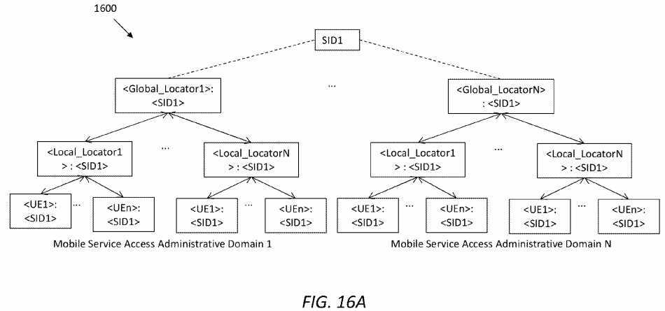
In the H-AP, a second-level of late-binding may be done to bind the service with a proper radio access network. In the second level of the tree?1600, the local_locator may refer to a PoA. Considering that the service may be provided by any mobile device, a third and last level of late-binding may be done in the PoA, which may forward the interest to a proper UE. As a result, the late-binding tree?1600?may enable service transparency to the public Internet.
To construct a service late-binding tree, a SAST may be used to track where a service is published. Further, an MST may be designed to help determine the path to an actual location of the service by traversing the service late-binding tree. Before going to detail on how to manage service mobility in terms of device mobility, a general process of network registering a mobile device and a service publishing process from a mobile device will be described first.
FIG. 16B?illustrates an embodiment of a service domain?1650, in which network registration and service registration may be performed to handle heterogeneous mobility. The service domain?1650?may comprise a UE?1652?and a G-SAP?1660, which in turn may comprise a PoA?1662, an H-AP?1664, and an SRN?1666. Functional modules of each of these devices have been described previously. As shown in?FIG. 16B, the UE?1652?may be registered in the H-AP?1664?before providing any service. In network registration of the UE?1652, the PoA?1662?may work as an agent between the UE?1652?and the H-AP1664?to process network attachment. Further, in registration of a service from a service pool in the domain?1650, the H-AP1664?may work as an agent between the UE?1664?and the SRN?1666?to process service publish messages. Note that service registration may or may not be done at the same time with network registration
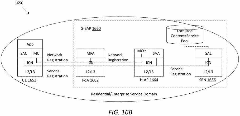
FIG. 17A?illustrates an embodiment of a UE registration process?1700. Suppose, for example, a user named Alice plans to publish her personal album access service with attributes (SID1=Hash_{PubKeyAlice}:/Alice/Personal_Album/:/ATT/SRS) from her smartphone (shown as UE?1702) through an AT&T LTE network. Before publishing a service, the UE?1702?may complete network connectivity registration using the process?1700, and a PoA?1710?may serve as a proxy to register the UE?1702?at an H-AP?1720?(at is denoted as @ in drawings).
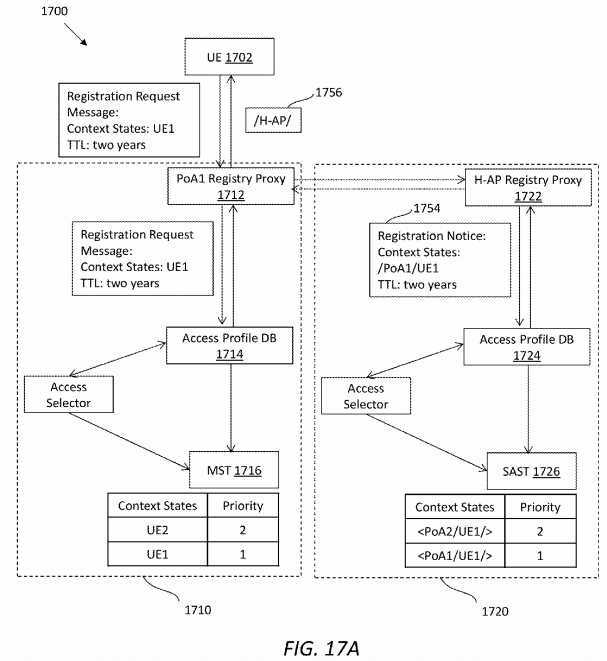
Alice would like to connect her smartphone to the AT&T LTE network. Thus, a MA (e.g., the MA?720) in the UE?1702?may first send a registration request message?1752?to a network registry proxy?1712?in the PoA?1710?of the LTE network. The PoA?1710?may update its access profile DB?1714?after receiving the registration request message?1752. The PoA?1710may further update its MST?1716?with the smartphone‘s access context states. In the MST?1716, the priority for a new registered UE may be set to a highest priority by default, e.g., with value of 1.
The PoA?1710?may also send a registration notice or notification message?1754?about the registration of Alice‘s smartphone to a network registry manager or proxy?1722?in the H-AP?1720, where the PoA1?has already registered with. The H-AP may then update its access profile DB?1724?and its SAST?1726?with the UE‘s access context states. Note that, in the SAST1726, an access context state entry may have the names of both the PoA?1710?and the UE?1702. When the PoA?1710?gets a response from the H-AP?1720, the PoA?1710?may send an acknowledgement response message?1756?to the UE?1702with an H-AP prefix (denoted as /H-AP/).
FIG. 17B?illustrates an embodiment of a work flow?1770?to represent the UE bootstrap process?1700?in the form of a message exchange protocol. As shown in?FIG. 17B, a MA in the UE?1702?may first send a registration request message1752?to the network registry proxy?1712. The PoA?1710?may update its access profile DB?1714?after receiving the registration request message?1752. The PoA?1710?may further update its MST?1716?with the smartphone‘s access context states. In the MST?1716, the priority for a new registered UE may be set to a highest priority by default, e.g., with value of 1. Next, the PoA?1710?may send a registration notice?1754?about the registration of UE?1702?to the network registry manager?1722?in the H-AP?1720, where the PoA?1710?has already registered with. The H-AP?1720?may then update its access profile DB?1724?and its SAST?1726?with the UE‘s access context states. Note that, in the SAST?1726, an access context state entry may have the names of both the PoA?1710?and the UE?1702. When the PoA?1710?gets an acknowledgement response?1758?from the H-AP?1720, it may send the acknowledgement response message?1756?to the UE?1702?with an H-AP prefix.
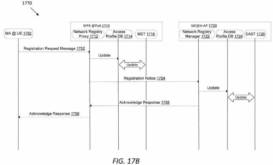
FIG. 18A?illustrates an embodiment of a service publishing process?1800?from the UE?1702, and?FIG. 18B?illustrates a work flow?1870?of the process?1800. Assume that the UE?1702?has already registered network connectivity at the H-AP?1720. When a service is published at UE?1702, the UE?1702?may send a publishing message?1812?to the H-AP?1720, and the publishing message?1812?may comprise a pre-defined priority value and a locator being the UE?1702. Upon receiving the publishing message?1812, the H-AP?1720?may insert a new entry into the SAST?1726, and update the publishing message1812?with new locator information, which may use the H-AP?1720?instead of the UE?1702, thereby generating an updated publishing message?1814.
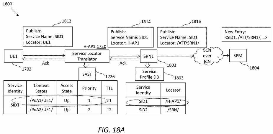
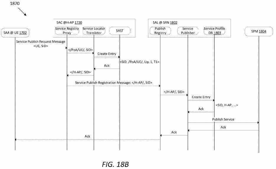
Then, the H-AP?1720?may send the updated publishing message?1814?to an SRN?1802, which may further update the service locator as the SRN?1802, thereby generating an updated publishing message?1816. Note that the service locator may be a routable name of the entity that provides the service in the framework. The SRN?1802?may then publish the service to a SPM?1804?via an ICN network. Note that once the publishing message?1814?arrives at the SRN?1802, the SRN1802?may update its service profile DB?1803?with the name of the new service and locator H-AP?1720. The service profile DB?1803?may be used to find where a service is hosted within a domain wherein the SRN?1802?resides. Note that other messages, such as acknowledgements, although not elaborated, may be exchanged between the network devices, as one of ordinary skill in the art will recognize.
A service may be locally forwarded.?FIG. 19A?illustrates an embodiment of a work flow?1900?for routing an arrived service interest from an SRN1?to a mobile device. An ICN core network may forward the service interest of SID1?from the consumer to the SRN denoted as "/ATT/SRN1/". The SRN1?may process the service interest and query its service profile DB to find the locator for SID1. In the example shown in?FIG. 19A, SID1?is published by H-AP1, so SRN1?may change the routing prefix to H-AP1?and then forward the interest. With the ICN transport, the interest may arrive at H-AP1, where a service engine may first look up a corresponding service name in a SAST. By checking the SAST, the Service Engine may find out that SID1?is published from both /PoA1/UE1/and /PoA2/UE1/, and that they have the same priority. In this case, the H-AP1?may check its MST and find that /PoA1/UE1/has a higher priority than /PoA2/UE1/, so the H-AP1?may update the routing prefix with /PoA1/UE1/for the service interest. Then, the H-AP1?may forward the service interest to PoA1, which in turn forwards it to UE1.
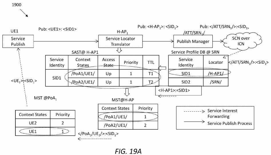
FIG. 19B?illustrate an embodiment of a network framework or architecture?1910, which may be utilized to realize contextualized edge-cloud service objectives. Diverse services, such as content distribution, social network, banking, and gaming, may be provided by one or more ASPs. The diverse services may be enabled over an ICN-SP network through contractual service layer agreements (SLAs) overlaid on virtualized computation, storage, and bandwidth resources. The user may send out a service request comprising a service ID along with contexts to any of the ASPs through the ICN-SP, and in return, receive a service response comprising the service ID and returned data.
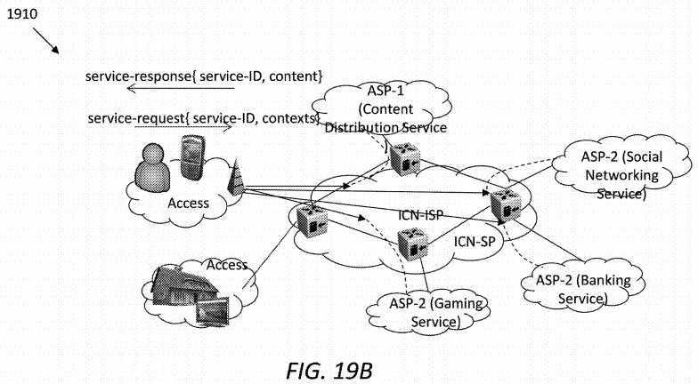
As a specific service example,?FIGS. 19C and 19D?illustrate an implementation?1920?in which an ASP (denoted as ASP-x)1922?is providing video service with personalized translation to its consumers including a UE?1924. In this case, the UE?1924may request video service with a language of choice, and an in-network service may decompose the request to three services: (1) extracting the video file from the video storage; (2) extracting the audio file; and (3) routing the extracted audio file through a translation service instance and then merging it with the video content to generate the service-response.
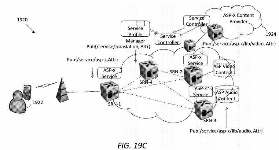
For illustrative purposes, we may assume the ASP-x?1922?has negotiated an edge-cloud service agreement with the ICN-SP. Service provisioning may be performed such that virtual computing and storage resources in routers denoted as SRN1, SRN2, and SRN3 may be dedicated to support the video service by ASP-x?1922. Service resolution may be enabled by publishing the service with desired attributes (e.g. lifetime) by the SAPs in routers SRN1, SRN2 and SRN3. Here, SRN1 may resolve to process the service request, while SRN2 and SRN3 may resolve to the video and/or audio content storage of ASP-x?1922.
The service and the storage instances may be distinguished through their namespace. For example, the SRN1 may process user requests under a service name: /service/asp-x, the SRN2 may serve video content under a service name: /service/asp-x/lib/video, and the SRN3 may serve audio content under a service name: /service/asp-x/lib/audio. Further suppose that another ASP or the ISP itself may have an instance of audio translation service in the SRN4 that is published under the service name: /service/audio/translation.
Subsequently, as shown in?FIG. 19D, when a user request for video service denoted as /service/asp-x/movie-1 arrives at the SRN1, a service orchestration process in the SRN1 may decompose the service, and a service logic graph?1926?as shown in?FIG. 19D?may be generated. The service logic graph?1926?may then be embedded as a service navigation vector to execute service functions. In the implementation?1910, the service request from the user?1924?to obtain video and translated audio content may be processed as parallel service functions, which may be finally composed at SRN1 to generate the service response for the user?1924.
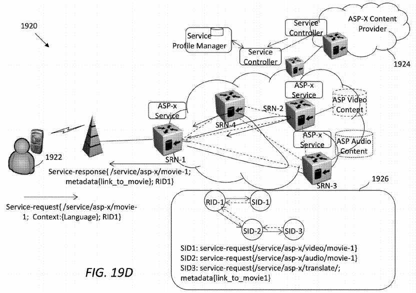
Next to describe relates to how the disclosed ICN-based SCN framework manages service producer mobility, which includes both intra and inter G-SAP service producer mobility management. An ISP may provide multiple network access technologies for a UE. For instance, a mobile device UE may switch connectivity between different radio access networks within the same ISP domain. The mobility management in one ISP domain may also be referred to as inter radio access technology mobility management. This mechanism may also be similarly applied in a more general inter network-access technology mobility management.
FIG. 20?illustrates an embodiment of a mobility management scheme?2000. Assume that, in a service domain?2010, a service provider or producer?2012?(identifiable by UE1) is using an AT&T LTE access or connectivity?2014?to provide a personal album access service (identifiable by SID1) to the general public. Assume the service producer?2012?is moving from the AT&T LTE access?2014?to an AT&T WiFi access?2016?while providing the service. Note that both accesses?2014and?2016?belong to AT&T. As shown in?FIG. 20, an H-AP1?2018?is coupled to the LTE access?2014?via a PoA1?2020, and coupled to the WiFi access?2016?via a PoA2?2022. The LTE access?2014?may comprise a number of base stations denoted as eNb1 and eNb2, and the WiFi access?2016?may comprise a number of access points (AP) denoted as AP1 and AP2. Both the eNbs and APs may be access points from the perspective of the network layer, but within different radio access layers. The LTE access?2014?may use an Evolved UMTS (Universal Mobile Telecommunications System) Terrestrial Radio Access (EUTRA) interface. Further, assume that an MST at the PoA1?2020?and an MST at the H-AP1?2018?already have a record about the network attachment of the service provider?2012, and that the SAST at the H-AP1?2018?also stores an entry about the access context for SID1, which is /PoA1/UE1/with a highest priority.
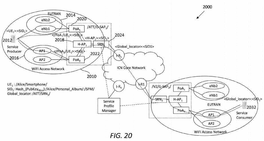
In an embodiment, when the service provider?2012?decides to use the WiFi access?2016?to provide SID1, there may be a few steps to be finished. A first step is to register the new network connection. More specifically, UE1?may register at the PoA2?2022, which notifies the H-AP1?2018?about the new registration of UE1. Then, the PoA2?2022?and the H-AP1?2018?may update their MSTs with the new access context information, respectively. The priority value for UE1‘s new connection may be set as the highest priority by default in the MSTs at both the PoA2?2022?and the H-AP1?2018. Moreover, the MST at the service engine may be synchronized.
In a second step, an MC and a SAC at the H-AP1?2018?may coordinate with each other about the new network access (i.e., access?2016) from UE1, and update the SAST with a new access context state and other relevant entries for SID1. The SAST at the service engine may be synchronized.
When the new connection is setup, UE1?may make a de-registration request to PoA1?2020, which may notify the H-AP12018?about this de-registration. Then H-AP1?2018?and PoA1?2020?may update their MSTs respectively. At H-AP1?2018, the MC may coordinate with the SAC to update the service access status for SID1?through /PoA1/UE1/(e.g., service from up to down). Because the UE1?may not send a message saying it will no longer use the LTE access?2014?to offer service access, the other fields in the SAST may be kept for the /PoA1/UE1/. Therefore, both MST and SAST at the service engine may be updated.
The changing of access network may remain transparent to service consumers including a service consumer?2032, as an intra domain handover may not affect a global locator of the service SID1. Since both the accesses?2014?and?2016?belong to AT&T, it may still be /ATT/SRN1/that is the result of service resolution. When an interest arrives at an SRN1?2024, the SRN1?2024?may check its service profile DB. If the SRN1?2024?determines that SID1?is available from H-AP1?2018, it may update the routing prefix as H-AP1?2018?and forwards the interest to H-AP1?2018.
Depending on the situation, the forwarding of an incoming interest at the H-AP1?2018?may be conducted differently. In a first exemplary case, before H-AP1?2018?updates its MST with the new network access context states from UE1, a SAST in the H-AP1?2018?has not been updated with the new access context either. In the first case, the H-AP1?2018?may still forward the interest to the PoA1?2020?(/PoA1/UE1/).
In a second exemplary case, if the H-AP1?2018?is processing the de-registration request from UE1?and updating an MST in the H-AP1?2018, the incoming interest may be cached until both MST and SAST in the H-AP1?2018?have been updated. After that, a Service Engine in the H-AP1?2018?may check the SAST and determine that the service SID1?is accessible from both /PoA1/UE1/and /PoA2/UE1/, and both have the same priority. Further, the Service Engine may check its MST and determine that both /PoA1/UE1/and /PoA2/UE2/have the same priority for the access. In the second case, the H-AP1?2018may bi-cast the interest to both PoAs?2020?and?2022, which then forward the interest to the UE1. More, the H-AP1?2018may bi-receive service received data from both PoAs?2020?and?2022, select the first arrived data, and send it back to the consumer?2032?via the SRN1?2024?and other network devices.
In a third exemplary case, the interest may arrive at the PoA1?2018?which is currently processing de-registration from UE1. In the third case, the interest may be dropped. In a fourth exemplary case, the interest may arrive at the UE1, which is about to de-register with the PoA1?2018. In the fourth case, the UE1?may send the data back to the H-AP1?2018, not via the PoA1?2020?but via the PoA2?2022.
Ideally, we expect a make-before-break handoff to provide seamless services such as VoIP or real-time applications on a mobile device, while the mobile device is moving between two ISP networks (e.g., AT&T and SPRINT). However, some of today‘s mobile devices have only one interface for one radio access technology, e.g., with one global system for mobile (GSM) subscriber identification module (SIM) card per device. Thus, a break-before-make handoff can be used to realize inter G-SAP service producer mobility management.
FIG. 21?illustrates an embodiment of an inter G-SAP service producer mobility management scheme?2100. The scheme2100?assumes that an ISP for Alice‘s home network is SPRINT, thus a service domain?2140?comprising Alice‘s UE1?2142belongs to SPRINT. Further, the scheme?2100?assumes that Alice would like to connect the UE1?2112?to a foreign network AT&T, which is represented by an AT&T service domain?2110.
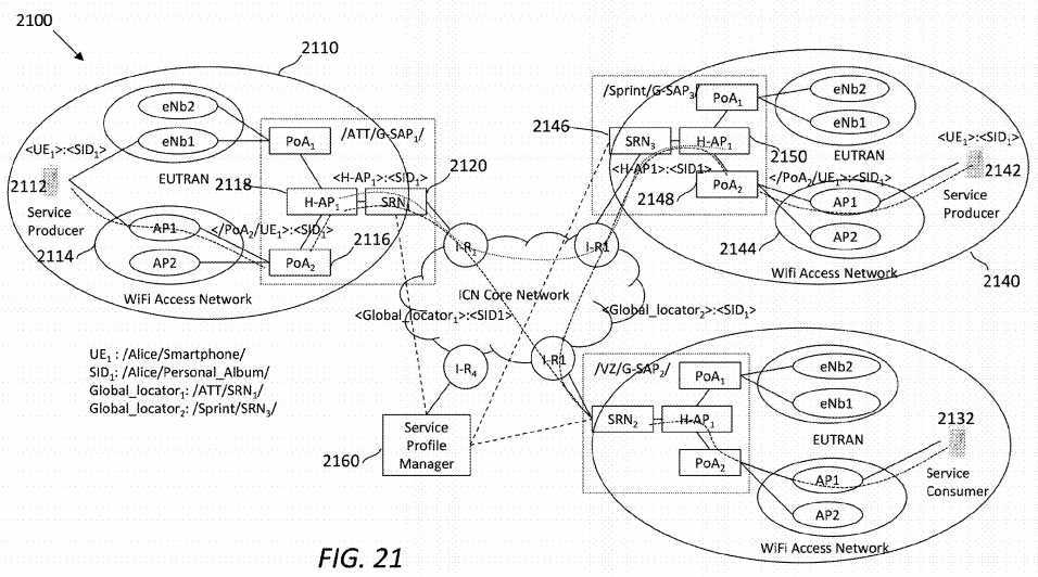
As shown in?FIG. 21, Alice was originally using a WiFi access?2144?in the SPRINT domain?2140?to provide her personal album access service (identifiable via and denoted as SID1) and now wants to move to a different location which uses a WiFi access?2114?in the AT&T domain?2110. In this case, a global location for the personal album access service may no longer be "/SPRINT/SRN3/." An embodiment of a break-before-make handoff may comprise several steps.
Before the handoff happens, the UE1?2142?resides in the home network—SPRINT domain?2140. Thus, a service provide DB located in an SRN3?2146?which resides in the domain?2140, may keep a record about the location of SID1. The location may be an H-AP1?2150. An SAST in the H-AP1?2150?may store the SID1, which is available from /PoA2/UE1/.
Next is a de-registration process which may include two sub-cases. A first exemplary sub-case assumes that the UE1?2142is permanently disconnected from the WiFi access?2144, and SID1?is permanently removed from the domain?2140. A second exemplary sub-case assumes that the UE1?2142?is temporarily disconnected from the WiFi access?2144, and SID1is expected to be offered in the domain?2140?in the future.
In the first exemplary sub-case, the UE1?2142?may send a permanent de-registration request to the PoA2?2148?in the service domain?2140?(home network). The PoA2?2148?may notify an H-AP1?2150?which connects the PoA2?2148?and the SRN3?2146. Both PoA2?2148?and H-AP1?2150?may remove relevant entries from their MSTs, respectively. At the H-AP12150, an MC may communicate with a SAC about this permanent disconnection by UE1?2142, so the SAC may remove the entries corresponding with /PoA2/UE1/. If /PoA2/UE1/is the only access context for SID1?in the SAST of the H-AP1?2150, the SAC may send a message to a service publish manager at the SRN3?2146. The publish manager may then remove the record about SID1?from a Service Profile DB in the SRN3?2146. Afterwards, the publish manager may further update a record in a SPM?2160. Note that, during this process, the MST and SAST in a service engine may be updated accordingly.
In the second exemplary sub-case, the UE1?2142?may send a temporary de-registration request to the PoA2?2148?in the domain?2140. The PoA2?2148?may send a notice to the H-AP1?2150?about the disconnection of the UE1?2142. Then, the H-AP1?2150?and the PoA2?2148?may update their MSTs, respectively, and the H-AP1?2150?may update its SAST. Since the disconnection of the UE1?2142?is temporary, the SAST of the H-AP1?2150?may update the service access status but may not remove the whole entry. During this procedure, the UE1?2142?may stop responding to interests, thus all incoming interests may be cached at the H-AP1?2150. Further, since SID1?is not permanently removed from the H-AP1?2150?and the SRN3?2146, global service resolution may still result in /SPRINT/SRN3/as SID1‘s global locator.
As shown in?FIG. 21, the UE1?2142?roams to a different ISP network—AT&T network, thus it is represented using a different UE1?2112?(UE still the same but location changed). The UE1?2112?may not officially decide to publish service through the AT&T network, so the D portion in the <P:I:D> form of the SID1?may not change. The UE1?2112?may send network registration via the WiFi access?2114?to PoA2?2116?in the AT&T domain?2110. The PoA2?2116?may notify an H-AP12118?in the domain?2110?accordingly.
Once both the H-AP1?2118?and the PoA2?2116?in the AT&T service domain?2110?update their MSTs, MCs residing in both the H-AP1?2118?(/AT&T/SRN1/H-AP1/) and the H-AP1?2150?(/SPRINT/SRN3/H-AP1/) may coordinate with each other about the mobility of UE1. More specifically, an MC in the H-AP1?2118?may notify its coupled SAC that the H-AP1?2118?is the new resolution point for SID1. Then, the SAC in the H-AP1?2118?may send one or more control messages to the SRN3?2146?via an SRN1?2120. The SRN3?2146?may communicate with the SRN1?2120?(/AT&T/SRN1/) to update a service profile DB in the SRN1?2120?about SID1‘s current access context in the AT&T domain?2110.
On the other hand, the SRN3?2146?may send a control message to a SRS, which is represented as D in the SID1‘s<P:I:D> form. The SRS may add a new resolution point for SID1?in a name resolution record, and mark the old resolution point of the SRN3?2146?as temporarily unavailable. Therefore, when a new service resolution request is sent to the SRS, the SRS may return with the SRN1?2120?as the global locator for SID1.
If the UE1?2112?moves back to its original home network the SPRINT domain?2140, the SPM?2160?may remove the temporary resolution point of SRN1?2120?and update the SRN3?2146?as available again. In this way, triangular routing can be avoided.
If the UE1?2112?decides to use AT&T as the home network for SID1?in a future time, the UE1?2112?may send a new service publish message to the H-AP1?2118, which may then update its SAST with a permanent record. The SRN1?2120?may update its service profile DB as well. The permanent update may affect service resolution results in the future. Note that re-homing may also result in new <P:I:D> which should be republished. A new global locator for SID1?may be the SRN1?2120. Therefore, when a service consumer?2132?resolves the service name again, the service consumer?2132?may get the new global locator of the SRN1?2120?for the SID1. Accordingly, the interest may be forwarded to the AT&T service domain?2110directly.
The scheme?2100?may not affect the service consumer?2132?in terms of service navigation, although the service domain has been changed from 2140 to 2110. In use, if the UE1?moves to a different service domain, and the UE1?does not republish SID1?globally, an interest from the service consumer?2132?may still be forwarded to the UE1?via the home network (i.e., the SPRINT service domain?2140). The SRN3?2146?may indicate that the service is available from H-AP1?2150. The interest from the service consumer?2132?may arrive at the H-AP1?2150, which may check its SAST and determines that SID1?is currently provided by the SRN1?2120?in the AT&T service domain?2110. In this case, the H-AP1?2150?may use a prefix of /ATT/SRN1?as the routing prefix. The interest may be re-forwarded to the AT&T service domain?2110?and reach the UE12112?by indirection at the H-AP1?2118. As shown by the scheme?2100, mobility may be realized on the SAP level or between domains.
As mentioned previously, embodiments of the disclosed ICN-based SCN framework may enable a whole network to behave like a datacenter, which is referred to as Network-As-A-Datacenter.?FIG. 22?illustrates an embodiment of a Network-As-A-Datacenter model?2200. Service applications may be provided collocated with content routers, which may be in collocated data centers or third party domains, so the whole core network may be considered as a data center. For example, a variety of services provided by different entities, such as GOOGLE, AMAZON, YAHOO, NETFLIX, BLOG.COM, and other ISPs may be made accessible to UEs located in different domains, such as an ISP domain?2210?and a third-party domain?2220. The services may be accessed via G-SAPs?2212?and?2222, the details of which have been described in detail.
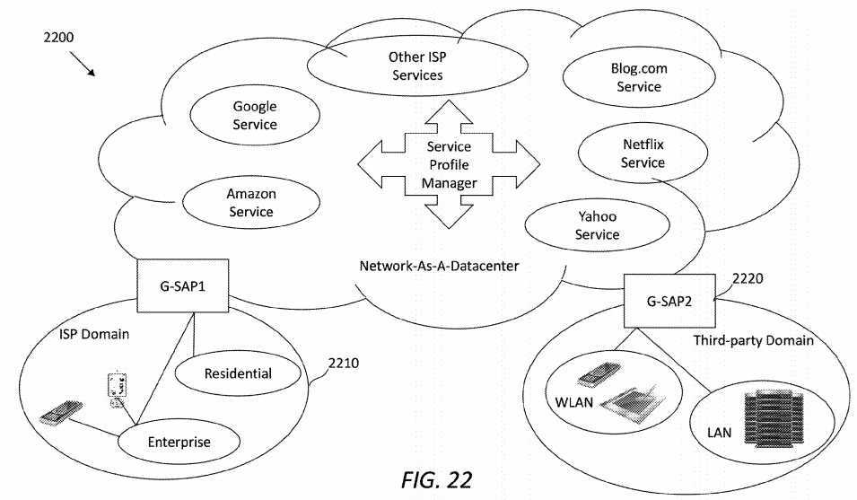
Each of the G-SAPs?2212?and?2222?may comprise an SRN. An SRN residing in the home network of service consumer(s) may work as a service access proxy to various types of services, including extra context-aware services and service primitives that collaborate with each other to fulfill one service interest. The SRN may be the entry point to the datacenter model?2200. Once the SRN receives an interest from a consumer, the SRN may interpret the service request and contexture information of the consumer. Further, the SRN may decompose the request into multiple services and creates a service logic graph to help navigate service interests.
For each domain that publishes services, there may be an SRN at the edge of the domain serving as a service gateway. When an interest to a particular service in the domain arrives at the SRN, the SRN may decompose a service interest into multiple tasks, which may be performed at one or more servers. The servers may host instances of the same application but may have different network resource allocations. A corresponding service publisher may decide to deploy a service instance at a different domain, e.g., according to statistics of consumer requests and other contextual information. Thus, an actual routing path of services at the ICN transport layer may be changed dynamically, although the service logic graph keeps the same.
FIG. 23?illustrates an embodiment of a service processing method?2300, which may be implemented by a network device residing in a service domain and functioning as an SRN (e.g., the SRN?132?or?200). The SRN may comprise an ICN transport layer (e.g., the ICN layer?214) and a SAL (e.g., the SAL?220) for handling context-aware service logistics and service mobility overlaid on the ICN transport layer. The service logistics may include, for example, service management functionalities such as discovery and service request. The method?2300?starts in step?2310, in which the SRN may receive, in the ICN transport layer, a message comprising a service request that originates from a UE. In step?2320, the SRN may retrieve, in the SAL, contextual information from the service request that is relevant to the UE or an access network connected to the UE. In an embodiment, the access network may be a wired, wireless, or mobile connection connected to the UE, and the contextual information may include at least one of device context of the UE, mobility context of the UE, environment context of the UE, context of the access network, and personal or social context of a service consumer using the UE.
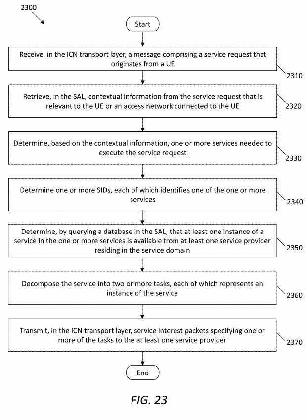
In step?2330, the SRN may determine, based on the contextual information, one or more services needed to execute the service request. In step?2340, the SRN may determine one or more SIDs, each of which identifies one of the one or more services. Although not shown in?FIG. 23, in an embodiment, determining the one or more SIDs may comprise translating the contextual information into a service description written in a standard service description language, and resolving the service description to the one or more corresponding SIDs by using a policy database (e.g., the policy DB?236) in the SAL. In step2350, the SRN may determine, by querying a database (e.g., the service profile DB?240) in the SAL, that at least one instance of a service in the one or more services is available from at least one service provider residing in the service domain. In step?2360, the SRN may decompose the service into two or more tasks, each of which represents an instance of the service. In step?2370, the SRN may transmit, in the ICN transport layer, service interest packets specifying one or more of the tasks to the at least one service provider
FIG. 24?illustrates an embodiment of a service processing method?2400, which may be implemented by a network device functioning as a PoA (e.g., the PoA?600). The method?2400?starts in step?2410, in which the PoA may receive a request for network registration from a UE. In step?2420, the PoA may retrieve, from the request, access context of the UE which identifies the UE. In step?2430, the PoA may update one or more data structures (e.g., the MST?618) in the PoA to include the access context and a default priority set for the UE. In step?2440, the PoA may send, to the UE, a prefix of the PoA as a response to the request. In step?2450, the PoA may send, to an H-AP, a message notifying the H-AP of the registration request from the UE, wherein the PoA has registered with the H-AP.
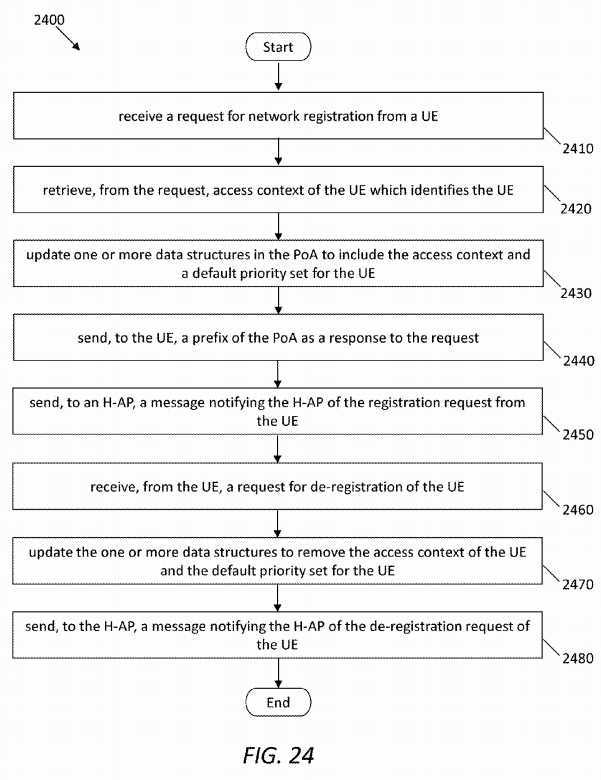
Further, in step?2460, the PoA may receive, from the UE, a request for de-registration of the UE. In step?2470, the PoA may update the one or more data structures to remove the access context of the UE and the default priority set for the UE. In step?2480, the PoA may send, to the H-AP, a message notifying the H-AP of the de-registration request of the UE. A person of ordinary skill in the art will recognize that variations of the methods, such as adding additional steps, skipping or merging some steps, and changing execution orders, may exist and are within the scope of this disclosure.
FIG. 25?illustrates an embodiment of a network device or unit?2500, which may be configured to facilitate transportation of ICN service flows or optical flows through a network. The network device?2500?may comprise one or more ingress ports2510?coupled to a receiver?2512?(Rx), which may be configured for receiving service or optical flows comprising packets or frames, objects, options, and/or type length values (TLVs) from other network components. The network device?2500?may comprise a logic unit or processor?2520?coupled to the receiver?2512?and configured to process the packets or otherwise determine to which network components to send the packets. The logic unit or processor?2520?may be implemented using hardware or a combination of hardware and software. The network device?2500?may further comprise a memory?2522, in which one or more databases or data structures may be implemented. The network device?2500?may also comprise one or more egress ports?2530?coupled to a transmitter?2532?(Tx), which may be configured for transmitting packets or frames, objects, options, and/or TLVs to other network components. The logic unit or processor?2520, the receiver?2512, and the transmitter?2532?may also be configured to implement or support at least part of any of the schemes and methods described above, such as the service request processing method?300, the work flow?400, the service request decomposition scheme?1200, the service orchestration scheme?1300, the request routing scheme?1550, the UE registration process?1700, the work flow?1770, the service publishing process?1800, the work flow?1870, the work flow?1900, the mobility management schemes?2000?and?2100, and the service processing methods?2300?and?2400.
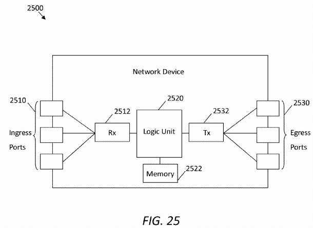
The schemes described above may be implemented on a network component, such as a computer or network component with sufficient processing power, memory resources, and network throughput capability to handle the necessary workload placed upon it.?FIG. 26?illustrates an embodiment of a computer system or network node?2600?suitable for implementing one or more embodiments of the systems disclosed herein, such as the SRN?200, the H-AP?500, the PoA?600, the UE?700, and the SPM?800?described above.
The computer system?2600?includes a processor?2602?that is in communication with memory devices including secondary storage?2604, read only memory (ROM)?2606, random access memory (RAM)?2608, input/output (I/O) devices?2610, and transmitter/receiver (transceiver)?2612. Although illustrated as a single processor, the processor?2602?is not so limited and may comprise multiple processors. The processor?2602?may be implemented as one or more central processor unit (CPU) chips, cores (e.g., a multi-core processor), field-programmable gate arrays (FPGAs), application specific integrated circuits (ASICs), and/or digital signal processors (DSPs). The processor?2602?may be configured to implement at least part of any of the schemes described herein, including the service request processing method?300, the work flow?400, the service request decomposition scheme?1200, the service orchestration scheme?1300, the request routing scheme?1550, the UE registration process?1700, the work flow?1770, the service publishing process?1800, the work flow?1870, the work flow1900, the mobility management schemes?2000?and?2100, and the service processing methods?2300?and?2400. The processor?2602?may be implemented using hardware or a combination of hardware and software.
The secondary storage?2604?is typically comprised of one or more disk drives or tape drives and is used for non-volatile storage of data and as an over-flow data storage device if the RAM?2608?is not large enough to hold all working data. The secondary storage?2604?may be used to store programs that are loaded into the RAM?2608?when such programs are selected for execution. The ROM?2606?is used to store instructions and perhaps data that are read during program execution. The ROM?2606?is a non-volatile memory device that typically has a small memory capacity relative to the larger memory capacity of the secondary storage?2604. The RAM?2608?is used to store volatile data and perhaps to store instructions. Access to both the ROM?2606?and the RAM?2608?is typically faster than to the secondary storage?2604.
The transmitter/receiver?2612?(sometimes referred to as a transceiver) may serve as an output and/or input device of the computer system?2600. For example, if the transmitter/receiver?2612?is acting as a transmitter, it may transmit data out of the computer system?2600. If the transmitter/receiver?2612?is acting as a receiver, it may receive data into the computer system?2600. Further, the transmitter/receiver?2612?may include one or more optical transmitters, one or more optical receivers, one or more electrical transmitters, and/or one or more electrical receivers. The transmitter/receiver?2612?may take the form of modems, modem banks, Ethernet cards, universal serial bus (USB) interface cards, serial interfaces, token ring cards, fiber distributed data interface (FDDI) cards, and/or other well-known network devices. The transmitter/receiver2612?may enable the processor?2602?to communicate with an Internet or one or more intranets. The I/O devices?2610?may be optional or may be detachable from the rest of the computer system?2600. The I/O devices?2610?may include a display. The I/O devices?2610?may also include one or more keyboards, mice, or track balls, or other well-known input devices.
It is understood that by programming and/or loading executable instructions onto the computer system?2600, at least one of the processor?2602, the secondary storage?2604, the RAM?2608, and the ROM?2606?are changed, transforming the computer system?2600?in part into a particular machine or apparatus (e.g. the SRN?200, the H-AP?500, the PoA?600, the UE?700, or the SPM?800?having the functionality taught by the present disclosure). The executable instructions may be stored on the secondary storage?2604, the ROM?2606, and/or the RAM?2608?and loaded into the processor?2602?for execution. It is fundamental to the electrical engineering and software engineering arts that functionality that can be implemented by loading executable software into a computer can be converted to a hardware implementation by well-known design rules. Decisions between implementing a concept in software versus hardware typically hinge on considerations of stability of the design and numbers of units to be produced rather than any issues involved in translating from the software domain to the hardware domain. Generally, a design that is still subject to frequent change may be preferred to be implemented in software, because re-spinning a hardware implementation is more expensive than re-spinning a software design. Generally, a design that is stable that will be produced in large volume may be preferred to be implemented in hardware, for example in an ASIC, because for large production runs the hardware implementation may be less expensive than the software implementation. Often a design may be developed and tested in a software form and later transformed, by well-known design rules, to an equivalent hardware implementation in an application specific integrated circuit that hardwires the instructions of the software. In the same manner, as a machine controlled by a new ASIC is a particular machine or apparatus, likewise a computer that has been programmed and/or loaded with executable instructions may be viewed as a particular machine or apparatus.
SRC=https://www.google.com/patents/US20140192717
Information Centric Networking Based Service Centric Networking,布布扣,bubuko.com
Information Centric Networking Based Service Centric Networking
标签:des style blog http color os strong io
原文地址:http://www.cnblogs.com/coryxie/p/3866871.html