标签:des style blog http color os strong io
An apparatus for performing network function virtualization (NFV), comprising: a memory, a processor coupled to the memory, wherein the memory includes instructions that when executed by the processor cause the apparatus to perform the following: receive an instruction to virtualize a network device within a network, divide, according to the instruction, the network device into a plurality of network functions (NFs) used to form a virtualized network node that corresponds to the network device, launch the NFs within one or more virtual containers, and group the virtual containers together using a group identifier (ID) that corresponds to the virtualized network node, wherein each of the NFs correspond to a network function performed by the network device prior to virtualization.
In today‘s service provider networks, network edge devices, such as provider edge (PE) nodes, are configured to offer virtual private network (VPN) services to one or more customers. For instance, a PE node can simultaneously offer VPN services at layer 3 (L3), such as Internet Protocol (IP) VPN and at layer 2 (L2), such as Virtual Private Wire Service (VPWS) and Virtual Private Local Area Network (LAN) Service (VPLS), to satisfy customer requirements. As the number of VPN sites continue to grow, service providers are constantly expanding their networks to accommodate the growing demand for network resources. To expand the networks, service providers have historically installed new data cards to existing PE nodes until the PE nodes utilize all of their expansion capacity. When the PE nodes no longer have the capacity to accommodate new data cards, new PE nodes may be installed within the service provider networks to compensate for additional resource requirements. However, adding and fully configuring new network devices (e.g. new PE nodes) to the network often involves substantial costs both in the form of capital expenditures (CAPEX) and operational expenditures (OPEX).
In an attempt to reduce CAPEX and OPEX, Network Function Virtualization (NFV), as described in the European Telecommunications Standards Institute (ETSI) group specification (GS) NFV 002 v1.1.1, entitled "Network Functions Virtualisation (NFV); Architectural Framework," published October 2013, which is incorporated herein as if reproduced in its entirety, consolidates many types of physical network devices onto one or more general purpose servers, switches, storage, and/or other general purpose network nodes. For example, NFV may implement network functions performed by a variety of physical network devices that include, but are not limited to switching elements (e.g. message routers and broadband network gateway), mobile network nodes (e.g. serving general packet radio service (GPRS) support node (SGSN)), traffic analysis (e.g. deep packet inspection (DPI) and quality of service (QoS) measurement), application level optimization (e.g. application accelerators and content distribution networks (CDNs)), and security functions (e.g. firewall). By consolidating the physical network devices, NFV provides greater flexibility for a network by implementing network functions that can be moved to and/or instantiated in various locations in the network without the installation and configuration of new physical network devices.
Unfortunately, current implementations of NFV address CAPEX reduction associated with network expansion, but do not fully address lowering the OPEX cost. One NFV virtualization technique, the appliance NFV method, treats a physical network device (e.g. PE node or Broadband Remote Access Server (BRAS)) as a single virtual appliance and embeds the entire physical network device into a virtual machine (VM) on a commodity server. For example, if the physical network device is a PE node, the appliance NFV method may implement the entire PE functionality as a single unit and embed all of the PE functionality within a single VM. Additionally, the PE data path can either be implemented on the same VM, or the PE data path can utilize the data path capabilities of commodity switches. As such, the appliance NFV method as described above primarily targets the CAPEX cost associated with expanding an existing PE node and/or adding a new PE node to the network. The appliance NFV method provides relatively low OPEX cost reduction because the newly added PE nodes may still need to be fully configured and installed within a service provider network.
In one embodiment, the disclosure includes an apparatus for performing NFV, comprising: a memory, a processor coupled to the memory, wherein the memory includes instructions that when executed by the processor cause the apparatus to perform the following: receive an instruction to virtualize a network device within a network, divide, according to the instruction, the network device into a plurality of network function units (NFs) used to form a virtualized network node that corresponds to the network device, launch the NFs within one or more virtual containers, and group the virtual containers together using a group identifier (ID) that corresponds to the virtualized network node, wherein each of the NFs correspond to a network function performed by the network device prior to virtualization.
In another embodiment, the disclosure includes an apparatus for performing NFV, comprising: a memory, a processor coupled to the memory, wherein the memory includes instructions that when executed by the processor cause the apparatus to perform the following: create a plurality of NFs that correspond to a plurality of network functions performed by a non-virtualized network device within a network, load the NFs within one or more virtual containers, group the virtual containers together using a group ID that identifies the network functions performed by a non-virtualized network device, monitor resource utilization for each of the virtual containers, and adjust resource allocation according to the resource utilization of each of the virtual containers.
In yet another embodiment, the disclosure includes a method for performing NFV, comprising: receiving an instruction to virtualize a PE device participating within a network, splitting the PE device into a plurality of NFs, wherein each of the NFs are used to perform a PE network function, grouping the NFs based on the instruction into one or more NF groups, placing each of the NF groups into a virtual container, and forwarding a plurality of data packets using the virtual containers.
Disclosed herein are at least one method, apparatus, and system that virtualize at least a portion of a physical network device using NFV. The NFV virtualization may virtualize the physical network device by dividing a physical network device into a plurality of NFs. Each of the NFs is configured to perform a network function typically implemented by the physical network device. A virtual container may host one or more of the NFs to address network scalability, expansion, and migration issues associated with the physical network device. The NFV virtualization may group and place the NFs within a virtual container using any one of the following: an absolute decomposition method, a network function decomposition method, and/or a service decomposition method in order to implement network functions performed by the physical network device. By virtualizing a physical network device into one or more NFs, the NFs may be distributed and arranged amongst virtual containers and/or hardware resource nodes to minimize OPEX costs.
FIG. 1?is a schematic diagram of an embodiment of an NFV system?100?where embodiments of the present disclosure may operate. The NFV system?100?may be implemented using a variety of networks, such as a data center network, service provider network, and/or a LAN. The NFV system?100?may comprise an NFV Management and Orchestration system?128, an NFV Infrastructure (NFVI)?130, a plurality of virtual network functions (VNFs)?108, a plurality of element management systems (EMSs)?122, a Service, VNF, and Infrastructure Description system?126, and one or more Operations Support Systems (OSSs) and Business Support Systems (BSSs) (OSS/BSS)?124. The NFV Management and Orchestration system128?may comprise an Orchestrator?102, one or more VNF managers?104, and one or more Virtualized Infrastructure Managers?106. The NFVI?130?may comprise computing hardware?112, storage hardware?114, and network hardware?116, a virtualization layer, a virtual computing?110, a virtual storage?118, and a virtual network?120. The Service, VNF, and Infrastructure Description Unit?126, and OSS/BSS?124?are discussed in more detail in the ETSI GS NFV?002?v1.1.1 standard.
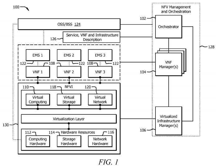
The NFV Management and Orchestration system?128?may be configured to perform supervisory and management functions for VNFs?108?and NFVI?130. The Orchestrator?102?may be configured to the NFVI?130?and the virtualization resources within the NFVI?130. The Orchestrator?102?may also realize network services (e.g. L2 and L3 VPN services) on the NFVI130. The Orchestrator?102?may communicate with one or more VNF managers?104?to implement resource related requests, send configuration information to the VNF managers?104, and collect state information of the VNFs?108. In addition, the Orchestrator?102?may communicate with the Virtualized Infrastructure Manager?106?to implement resource allocation and/or to reserve and exchange virtualized hardware resource configuration and state information. The VNF manager?104?may be configured to manage one or more VNFs?108. The VNF manager?104?may perform a variety of managing functions, such as instantiating, updating, querying, scaling, and/or terminating VNFs?108. The Virtualized Infrastructure Manager?106?may be configured to perform management functionalities that are used to control and manage the interaction of a VNF?108?with the computing hardware?112, storage hardware?114, network hardware?116, virtual computing?110?(e.g. VMs), virtual storage?118, and virtual network?120. For example, the Virtualized Infrastructure Manager106?may perform resource management functions, such as managing infrastructure resource and allocation (e.g. increase resources to virtual containers) and operation functions such as collecting NFVI fault information. The VNF manager?104?and Virtualized Infrastructure Manager?106?may communicate with each other for resource allocation requests and to exchange virtualized hardware resource configuration and state information.
The NFVI?130?comprises hardware components, software components, or a combination of both to build up the virtualized environment to deploy, manage, and execute the VNFs?108. In other words, the hardware resources and virtualization layer are used to provide virtualized resources, such as VMs and other forms of virtual containers, for VNFs?108. The hardware resources comprise the computing hardware?112, storage hardware?114, and network hardware?116. The computing hardware?112?may be commercial off-the-shelf (COTS) hardware and/or custom hardware used to provide processing and computing resources. The storage hardware?114?may provide storage capacity that may be provided within the network or resides within the storage hardware?114?itself (e.g. local memory located within a server). In one embodiment, the resources from computing hardware?112?and storage hardware?114?may be pooled together. The network hardware?116may be switches (e.g. commodity switches), routers, and/or any other network device configured to perform switching functions that are interconnected via wire and/or wireless links. The network hardware?116?may span across a plurality of domains and may comprise a plurality of networks that are interconnected via one or more transport networks.
The virtualization layer within the NFVI?130?may abstract the hardware resources and decouple the VNF?108?from the underlying physical network layer to provide virtualized resources to the VNF?108. As shown in?FIG. 1, the virtualized resources may comprise a virtual computing?110, a virtual storage?118, and a virtual network?120. Virtual computing?110and virtual storage?118?may be provided to the VNFs?108?in the form of hypervisors, VMs, and/or other virtual containers. For example, one or more of the VNFs?108?may be deployed on a VM. The virtualization layer abstracts the network hardware?116?to form the virtual network?120. The virtual network?120?may comprise virtual switches (Vswitches) that provide connectivity between the VMs and/or other virtual containers that host VNFs?108. The abstraction of hardware resources may be implemented using a variety of techniques that include, but are not limited to Virtual LAN (VLAN), VPLS, Virtual extensible LAN (VxLAN), and Network Virtualization using Generic Routing Encapsulation (NVGRE). Moreover, the transport network within network hardware?116?may be virtualized using a centralized control plane and a separate forwarding plane (e.g. Software Defined Network (SDN)).
As shown in?FIG. 1, VNF Manager?104?may communicate with VNFs?108?and EMSs?122?to perform VNF lifecycle management and exchange configuration and state information. VNF?108?may be configured to be a virtualization of at least one of the network functions performed by a physical network device. In one embodiment, the VNF?108?may be a virtualized PE node configured to provide all PE network functions typically found within a non-virtualized PE device. In another embodiment, the VNF?108?may be configured to implement one of the components (e.g. operations, administration, and management (OAM) component) for the non-virtualized PE device. As such, a virtual container may host a single VNF?108or may host a plurality of VNFs?108, where each VNF?108?runs in a virtual container and corresponds to a set of network functions belonging to one or more physical devices. Deploying VNFs?108?to perform network functions will be discussed in more detail in?FIGS. 4-9. The EMS?122?may be configured to perform manage functionality for one or more VNFs?108.
FIG. 2?is a schematic diagram of an embodiment of an NFV system?200?used to virtualize a PE device. The NFV system200?may comprise a PE Orchestrator?202, a Virtual Machine Manager?204, a networking system?206, a computing system208, and a storage system?210. The Virtual Machine Manager?204?may be substantially similar to the Virtualized Infrastructure Manager?106?as described in?FIG. 1. The networking system?206?may be substantially similar to virtual network?120?and network hardware?116?as described in?FIG. 1. The computing system?208?may be substantially similar to virtual computing?110?and computing hardware?112?as described in?FIG. 1. The storage system?210?may be substantially similar to virtual storage?118?and storage hardware?114?as described in?FIG. 1. The networking system?206, computing system?208, and storage system?210?may be used to form one or more server pools?212?shared by the NFV system?200. The server pools?212?may comprise servers S1-S3?214?and/or any other network device used to house PE VMs?216. The PE VMs?216?may comprise one or more NFs, where each of the NFs is configured to implement a network function performed by a non-virtualized PE device.
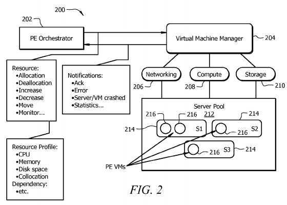
The PE Orchestrator?202?may be substantially similar to the VNF Manager?104?described in?FIG. 1, and may be hosted on a VM and/or other virtual container. In addition to functions performed by a VNF Manager?104, the PE Orchestrator?202may specifically coordinate and launch PE VMs?216. The PE Orchestrator?202?may provide PE VMs?216?information used to communicate with each other. For example, each virtualized PE node may be assigned a unique device ID and/or other grouping ID. In instances where the virtualized PE node is garmented into multiple NFs (e.g. multiple network functions) and each of the NFs are loaded onto a PE VM?216, the PE Orchestrator?202?may group together PE VMs?216?that have the same device ID. The PE VMs?216?that are grouped together may perform at least some of the network functions performed by a non-virtualized PE device. The PE Orchestrator?202?and/or the Virtual Machine Manager?204?may map the device ID to a virtualized network identifier provided by the underlying network (e.g. VLAN tag or Tunnel ID) to isolate the communications between the PE VMs?216?grouped together. The PE Orchestrator?202?may communicate with the Virtual Machine Manager?204?to handle various notification events and to manage overall resource management, such as reservation, allocation, modification, and movement, when launching and managing the PE VMs?216.
To improve OPEX, the PE Orchestrator?202?may monitor resource utilization and trigger resource allocations for the PE VMs?216. The PE Orchestrator?202?may monitor in real-time the resource usage (e.g. central processing unit (CPU), memory, and memory usage) and trigger dynamic re-allocation and modification of resources initially allocated to the PE VMs?216?used to represent the network device. The re-allocation and modification of resources may be implemented in a proactive manner (e.g. no network notification) or a reactive manner (e.g. after network notification). For example, resources may re-allocated and modified in a proactive manner when a network administrator or operator observes an increase in the number of supported network devices and subsequently instructs the PE Orchestrator?202?to allocate more resources to one or more PE VMs?216. Conversely, the PE Orchestrator?202?may re-allocate and modify resources in a reactive manner when the PE Orchestrator?202?receives a notification from a PE VM?216, a Virtual Machine Manager?204and/or other virtualized network nodes within the virtualized network.
PE Orchestrator?202?may also lower OPEX by performing PE VM?216?migration, depending on the network resource demand. In instances where the host server‘s?214?resources (e.g. CPU, memory, storage, etc.) are exhausted and may not support further resource demand for a PE VM?216, the PE Orchestrator?202?may trigger a move for the PE VM?216?to another server?214?with more capacity. Using?FIG. 2?as an example, if server S2?214?no longer has enough resources to satisfy the PE VM?216, then the PE Orchestrator?202?may trigger a move for the PE VM?216?on server S2?214. The PE Orchestrator?202?may send a request to the Virtual Machine Manger?204?that moves the PE VM?216?on server S2?214?to another server?214. Once the Virtual Machine Manager?204?receives the request, the Virtual Machine Manager?204?may move the PE VM?216?on server S2?214?to another server?214?(e.g. server S3?214).
As persons of ordinary skill in the art are aware, although?FIG. 2?and the disclosure illustrate performing NFV virtualization for a PE node, the disclosure is not limited to that application. For instance, the NFV virtualization may apply to other network devices, such as an IP router. Moreover, the PE Orchestrator?202?may be configured to manage NFs and/or a set of NFs that perform functions from one or more network devices. Additionally, although the disclosure references placing NFs within VMs (e.g. PE VMs?216), persons of ordinary skill in the art are also aware that other types of virtual containers besides VMs may be used to host NFs. The use and discussion of FIGS.?2?and?4-9?are only an example to facilitate ease of description and explanation.
At least some of the features/methods described in the disclosure may be implemented in a network element. For instance, the features/methods of the disclosure may be implemented using hardware, firmware, and/or software installed to run on hardware. The network element may be any device (e.g., a switch, router, bridge, server, client, etc.) that transports data through a network, system, and/or domain.?FIG. 3?is a schematic diagram of an embodiment of a network element?300?that may be used to transport and/or process data through NFV systems?100?and?200?as shown in?FIGS. 1 and 2. In one embodiment, the network element?300?may be any apparatus used to create, modify, relocate, and/or migrate one or more virtual containers (e.g. VMs). The network element?300?may also be any apparatus used to host, store, and/or execute one or more NFs. For example, network element?300?may be an NFV Management and Orchestration system?128?or one of is sub-components as described in?FIG. 1. In another embodiment, network element?300?may be a PE VM?216?as described in?FIG. 2.
The network element?300?may comprise one or more downstream ports?310?coupled to a transceiver (Tx/Rx)?312, which may be transmitters, receivers, or combinations thereof The Tx/Rx?312?may transmit and/or receive frames from other network nodes via the downstream ports?310. Similarly, the network element?300?may comprise another Tx/Rx?312?coupled to a plurality of upstream ports?314, wherein the Tx/Rx?312?may transmit and/or receive frames from other nodes via the upstream ports?314. The downstream ports?310?and/or upstream ports?314?may include electrical and/or optical transmitting and/or receiving components.
A processor?302?may be coupled to the Tx/Rx?312?and may be configured to process the frames and/or determine which nodes to send (e.g. transmit) the frames. In one embodiment, the processor?302?may comprise one or more multi-core processors and/or memory modules?304, which may function as data stores, buffers, etc. The processor?302?may be implemented as a general processor or may be part of one or more application specific integrated circuits (ASICs) and/or digital signal processors (DSPs). Although illustrated as a single processor, the processor?302?is not so limited and may comprise multiple processors. The processor?302?may be configured to implement any of the schemes described herein, including the absolute decomposition method, network function decomposition method, service decomposition method, and/or method?1000.
FIG. 3?illustrates that the memory module?304?may be coupled to the processor?302?and may be a non-transitory medium configured to store various types of data. Memory module?304?may comprise memory devices including secondary storage, read only memory (ROM), and random access memory (RAM). The secondary storage is typically comprised of one or more disk drives, solid-state drives (SSDs), and/or tape drives and is used for non-volatile storage of data and as an over-flow data storage device if the RAM is not large enough to hold all working data. The secondary storage may be used to store programs that are loaded into the RAM when such programs are selected for execution. The ROM is used to store instructions and perhaps data that are read during program execution. The ROM is a non-volatile memory device that typically has a small memory capacity relative to the larger memory capacity of the secondary storage. The RAM is used to store volatile data and perhaps to store instructions. Access to both the ROM and the RAM is typically faster than to the secondary storage.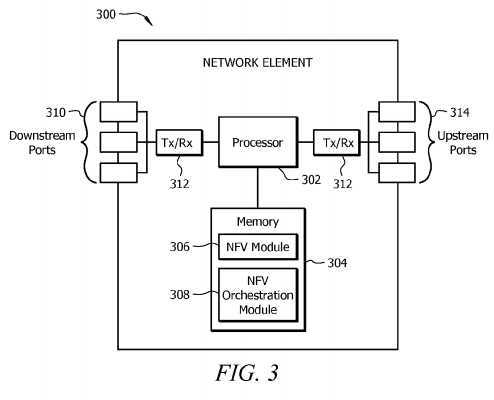
The memory module?304?may be used to house the instructions for carrying out the system and methods described herein, e.g., as a management entity?104, external entity?108, orchestration system?210, etc. In one embodiment, the memory module?304?may comprise an NFV module?306?that may be implemented on the processor?302. Alternately, the NFV module?306?may be implemented directly on the processor?302. The NFV module?306?may be configured to host, store, and execute one or more NFs for a virtualized network device. Hosting, storing, and executing one or more NFs will be discussed in?FIGS. 4-9. In another embodiment, the memory module?304?may also comprise an NFV orchestration module308?that may create, modify, relocate, and/or migrate one or more virtual containers. Additionally, the NFV orchestration module?308?may provide group information used to group together NFs, virtual containers, and/or other virtual network nodes. Creating, modifying, relocating, migrating, and grouping VMs and/or other virtual containers are discussed in more detail in FIGS.?2?and?4-10.
It is understood that by programming and/or loading executable instructions onto the network element?300, at least one of the processor?302, the cache, and the long-term storage are changed, transforming the network element?300?in part into a particular machine or apparatus, e.g., a multi-core forwarding architecture, having the novel functionality taught by the present disclosure. It is fundamental to the electrical engineering and software engineering arts that functionality that can be implemented by loading executable software into a computer can be converted to a hardware implementation by well-known design rules known in the art. Decisions between implementing a concept in software versus hardware typically hinge on considerations of stability of the design and numbers of units to be produced rather than any issues involved in translating from the software domain to the hardware domain. Generally, a design that is still subject to frequent change may be preferred to be implemented in software, because re-spinning a hardware implementation is more expensive than re-spinning a software design. Generally, a design that is stable that will be produced in large volume may be preferred to be implemented in hardware, for example in an ASIC, because for large production runs the hardware implementation may be less expensive than the software implementation. Often a design may be developed and tested in a software form and later transformed, by well-known design rules known in the art, to an equivalent hardware implementation in an ASIC that hardwires the instructions of the software. In the same manner as a machine controlled by a new ASIC is a particular machine or apparatus, likewise a computer that has been programmed and/or loaded with executable instructions may be viewed as a particular machine or apparatus.
FIG. 4?is a schematic diagram of an embodiment of a virtualized PE node?400?using an absolute decomposition method. The absolute decomposition method fragments or divides PE network functions into separate NFs. For the absolute decomposition method, a PE Orchestrator may launch virtual containers to host each NF. The virtual containers may be hosted on one or more servers that implement computing and/or storage network functions within a server farm?402. Virtual containers, Vswitches?430?within a virtual network, and/or commodity switches?432?within the underlying communication infrastructure (e.g. network hardware) may be used to implement the PE‘s data plane. The commodity switches?432?may be configured with different network encapsulation capabilities (e.g. Multiprotocol Label Switching (MPLS) encapsulation). In one embodiment, the underlying communication infrastructure and server farm?402?may be a data center network and/or a portion of a service provider network. The commodity switches?432?may include Ethernet switches, high performance switches, and/or other physical network nodes used to transport data within and/or outside the data center or server provider network. The Vswitches?430?may be virtualized network nodes also used to transport data within and/or outside the data center network or service provider network.
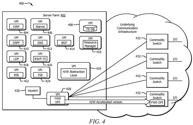
The absolute decomposition method treats a virtualized PE node?400?as the sum of a set of interworking NFs and allocates a virtual container to each component. As shown in?FIG. 4, the virtualized PE node?400?may comprise an OAM VM?404, an Alarms VM?406, a traffic engineering (TE) database (DB) VM?408, an Open Shortest Path First (OSPF) VM?410, an Intermediate System to Intermediate System (IS-IS) VM?412, a Border Gateway Protocol (BGP) VM?414, a resource manager VM?416, a Label Distribution Protocol (LDP) VM?418, a resource reservation protocol (RSVP)-TE VM?420, a routing information base (RIB) VM?422, a forwarding information base (FIB) VM?424, a hardware abstraction layer VM?426, a forwarding and DPI VM?428, and a Vswitch?430. OSPF VM?410, IS-IS VM?412, BGP VM?414, LDP VM?418, and RSVP-TE VM?420?may host NFs configured to perform OSPF, IS-IS, BGP, LDP, and RSVP-TE protocols, respectively. The OAM VM?404?may host an NF configured to perform OAM operations, and the Alarms VM?406?may host an NF configured to generate notifications or alarms originating from network errors or faults. The RIB VM?422?and FIB VM?424?may host NFs that comprise one or more tables used to route incoming data packets to the proper destination nodes. The hardware abstraction layer VM?426?may host an NF configured to store the mapping of the virtual resources (e.g. resources allocated to VMs) to hardware resources (e.g. server).
The resource manager VM?416?may host an NF configured to internally monitor the resources used for each of the VMs. Upon the initial launch and setup, each of the NFs hosted within a VM can be individually fine-tuned based on network dynamics and real time requirements. Recall that VM resource modification may be either proactive or reactive. For example, a network administrator or operator may observe a growth in the number of BGP peers in the network and can instruct the PE Orchestrator to allocate more CPU and/or memory resources to the BGP VM?414. Alternatively, each VM can be created based on a profile that indicates high water marks along with threshold limits for the VM‘s resources. The PE Orchestrator may monitor the VM resources by examining the notification events the PE Orchestrator receives from the Virtual Machine Manager and adjust the resources allocated to the virtual containers accordingly.
The virtualized PE node‘s?400?data plane may be implemented in virtual containers, Vswitches?430?on servers, and/or commodity switches?432?within the underlying communication infrastructure (e.g. network hardware?116?in?FIG. 1). The underlying communication infrastructure may be used to implement inter-process communication messages in a closed system and may be responsible for connecting the virtual containers together. In?FIG. 4, the forwarding and DPI VM?428may be used to instruct commodity switches?432?within the underlying infrastructure on how to encapsulate, forward, and inspect data packets. The forwarding and DPI VM?428?may use Open Flow and/or some other application program interface (API) to communicate with the commodity switches?432. The forwarding and DPI VM?428?may also augment the commodity switches?432?with specialized accelerator modules in scenarios that demand a high performance data plane.
Virtualizing PE node?400?using the absolute decomposition method may provide a valuable scalability advantage over a non-virtualized PE device. A non-virtualized PE device may not only be limited in terms of the number of CPUs, network processing units (NPUs), and the size of the memory and storage, but the non-virtualized PE device may also be constrained with respect to the number of data path modules and ports (e.g. input and output (I/O) ports). Once a non-virtualized PE uses all available port capacity, a network administrator or operator may need to install a new PE device in the network. In contrast, using the absolute decomposition method to virtualize a PE node?400?may not impose a physical hard limit on data plane resources. A network administrator or operator may install more commodity switches?432?to satisfy growing data path demands of a virtualized PE node?400?in order to prevent additional OPEX costs associated with installing a new PE. In other words, the OPEX cost of expanding a virtualized PE node?400?may be equal to the cost of adding a new data path module within a network that uses a non-virtualized PE, which is a lower OPEX cost than configuring a new non-virtualized PE.
FIG. 5?is a schematic diagram of an embodiment of a virtualized PE node?500?using a network function decomposition method. The network function decomposition method may virtualize a PE device by dividing the PE device into subcomponents based on network segment connectivity to form a virtualized PE node?500. Specifically, the network function decomposition method may split a PE device into a UNI subcomponent and an NNI subcomponent. The UNI subcomponent and the NNI subcomponent may be separated and implemented using separate VMs and/or other virtual containers. By splitting the PE device into the UNI subcomponent and NNI subcomponent, each subcomponent may be fine-tuned independently of each other. Moreover, splitting the PE device may provide network administrators and operators to offload network resources to the virtual environment. Example embodiments for implementing the UNI subcomponents and NNI subcomponent will be discussed in more detail in?FIGS. 6-8.
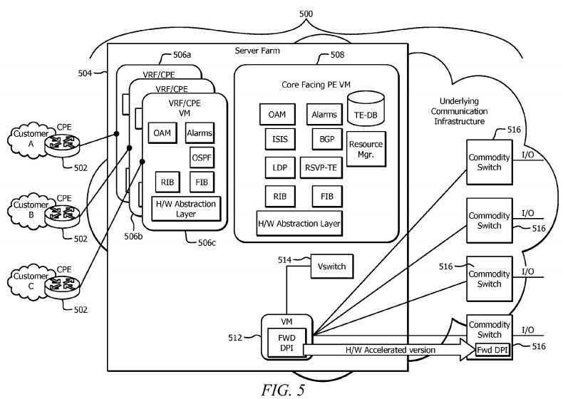
The UNI subcomponent may be configured to connect to a customer network to the virtualized PE node?500?and provide functionalities that are traditionally part of the VPN Routing and Forwarding (VRF), VPLS, and/or VPWS access component of a PE device. VRF, VPLS, and VPWS functionalities are described in more detail in the Internet Engineering Task Force (IETF) Request for Comments (RFC) 4026, entitled "Provider Provisioned Virtual Private Network (VPN) Terminology," published March 2005, which is incorporated herein as if reproduced in its entirety. The UNI subcomponent may communicate with a CPE node?502?to connect to a customer network.
FIG. 5?illustrates that the UNI subcomponent may be hosted using VRF/CPE VMs?506a-c. VRF/CPE VMs?506?a,?506?b,506?c?may be used to connect to customer A network, customer B network, and customer C network, respectively. Each of the VRF/CPE VMs?506?a-c?may comprise a plurality of NFs that correspond to PE network functions performed by a UNI subcomponent. As shown in?FIG. 5, VRF/CPE VMs?506?a,?506?b,?506?c?may each comprise a plurality of NFs configured to implement the OAM, Alarms, OSPF, RIB, FIB, and hardware abstraction layer network functions that were described inFIG. 4?in order to connect to the customer networks. The CPE nodes?502?may be configured to perform typical CPE device network functions, such as routing, VPN termination, QoS support, DPI, firewall, and performing wide area network (WAN) Optimization Controller (WOC) functions.
The NNI subcomponent may be configured to manage internal network communications with the network that the virtualized PE node?500?is located in. For example, the NNI subcomponent may manage PE communications with a service provider‘s internal network and may be responsible for a variety of network functions, such as BGP peering, MPLS signaling, and VPN discovery. As shown in?FIG. 5, the NNI subcomponent may be hosted within the Core Facing PE VM?508. The Core Facing PE VM?508?may be a VM comprising a plurality of NFs that are configured to perform a variety of PE network functions that include, but are not limited to OAM, alarm, IS-IS, BGP, LDP, RSVP-TE, RIB, FIB, TE-DB, resource managing, RIB, FIB, and hardware abstraction layer functions, which were described in?FIG. 4. The server farm?504, Vswitch?514, forwarding and DPI VM?512, and commodity switches?516?are substantially similar to the server farm?402, Vswitch?430, forwarding and DPI VM?428, and commodity switches?432?as described in?FIG. 4, respectively.
FIG. 6?is a schematic diagram of an embodiment of an NFV system?600?that comprises a non-virtualized PE device?612operating along with a virtualized UNI subcomponent using the network function decomposition method. In this embodiment, the network function decomposition method may offload and move the UNI network functions (e.g. VRF/VPWS/VPLS functions) of a PE-1?device?612?to the virtual environment. The UNI functions are coupled to CPE-1?nodes?602?at the customer premises. The NNI function, remains in the non-virtualized PE-1?device?612, which is coupled to the service provider‘s core network?616. The data center?604?may comprise the NFV systems?100?and?200?as described in?FIGS. 1 and 2?to provide the connectivity between the virtualized and non-virtualized sides of the PE-1?device?612. The data center604?may be located within the service provider network or may be a network external to the service provider network.
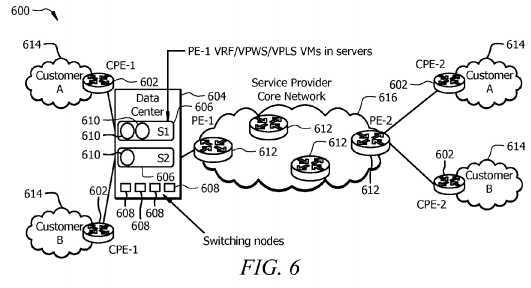
As shown in?FIG. 6, the non-virtualized PE-1?device?612?may implement the NNI functionality used to communicate with the service provider core network?616?and other non-virtualized PE devices?612. The servers?606?within the data center?604may comprise PE-1?VRF/VPWS/VPLS VMs?610?used to implement the UNI network functions used to connect to customer A and B networks?614?via the CPE-1?nodes?602. Switching nodes?608?may be substantially similar to the commodity switches?432?as described in?FIG. 4. As such, switching nodes?608?may be used to exchange data packets amongst the PE-1?VRF/VPWS/VPLS VMs?610, non-virtualized PE-1?devices?612, and/or the CPE-1?nodes?602.
When data packets arrive at the non-virtualized PE-1?device?612?from the service provider‘s core network?616, the data packets are initially processed by identifying their VRF component within the non-virtualized PE-1?device?612. Typically, the VRF component within the non-virtualized PE-1?device?612?is identified using one or more tags encapsulated within the data packet. However, because UNI network functions have been offloaded and virtualized, the data packets are forwarded to the corresponding PE-1?VRF/VPWS/VPLS VM?610?used to implement the VRF rather than forwarding the data packet to the VRF component within the non-virtualized PE-1?device?612. For outbound packets that are leaving a customer network614, the CPE-1?nodes?602?send the packets to their corresponding PE-1?VRF/VPWS/VPLS VMs?610?to initially process the data packets. Afterwards, the PE-1?VRF/VPWS/VPLS VMs?610?forward the packets to the non-virtualized PE for transmission to other peer non-virtualized PE devices?612?across the service provider‘s core network?616.
The offloading of the UNI functions for a PE device to virtual containers may free resources for the non-virtualized PE-1device?612?to be used for NNI functionalities. Also, by virtualizing the UNI functionality, a network administrator or operator can now expand the UNI side by instigating new PE-1?VRF/VPWS/VPLS VMs?610?and associating them with new customers and/or customer networks?614. The new PE-1?VRF/VPWS/VPLS VMs?610?may be hosted on the same servers (e.g. server S1?or S2?606) or on different servers?606. The PE-1?VRF/VPWS/VPLS VMs?610?may be independent of one another and may offer an inherent protection mechanism. Resources allocated to the PE-1?VRF/VPWS/VPLS VMs?610?can be individually fined-tuned to accommodate the customer‘s need, while the non-virtualized PE-1?device?612?remains intact.
FIG. 7?is a schematic diagram of an embodiment of an NFV system?700?that comprises a non-virtualized PE device?710operating along with a virtualized UNI subcomponent and a virtualized CPE component using the network function decomposition method. Data center?702, servers?704, switching nodes?708, non-virtualized PE devices?710, CPE nodes712, customer networks?714, and service provider core network?716?are substantially similar to the data center?604, servers?606, switching nodes?608, non-virtualized PE devices?612, CPE nodes?602, customer networks?614, and service provider core network?616?as described in?FIG. 6, respectively. The PE-1?VRF/VPWS/VPLS+CPE VMs?706?are substantially similar to the PE-1?VRF/VPWS/VPLS VMs?610?except that the PE-1?VRF/VPWS/VPLS+CPE VMs?706?also host typical CPE network functions. The CPE network functions include, but are not limited to firewall, web security, WAN acceleration and optimization, and routing functions. The CPE network functions may correspond to a second set of NFs, where each of the NFs within the second set of NFs corresponds to a CPE network function. The NFs corresponding to the CPE network functions and NFs corresponding to the UNI functions may be grouped and hosted by the PE-1VRF/VPWS/VPLS+CPE VMs?706. In another embodiment, the CPE network functions within the second set of NFs and the NFs corresponding to the UNI functions may be instigated onto separate VMs and may not be combined onto a single VM. A network administrator or operator may move CPE network functions to the virtualized environment to reduce CAPEX cost.
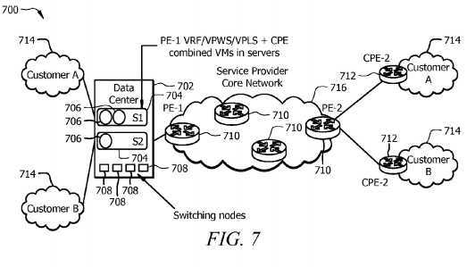
FIG. 8?is a schematic diagram of an embodiment of an NFV system?800?that comprises a virtualized UNI subcomponent, a virtualized NNI subcomponent, and a virtualized CPE component using the network function decomposition method. Data center?802, servers?804, switching nodes?808, non-virtualized PE devices?812, CPE nodes?814, customer networks?816, and service provider core network?818?are substantially similar to the data center?604, servers?606, switching nodes?608, non-virtualized PE devices?612, CPE nodes?602, customer networks?614, and service provider core network?616?as described in?FIG. 6, respectively. The VRF/VPWS/VPLS+CPE VMs?806?are substantially similar to the PE-1VRF/VPWS/VPLS+CPE VMs?706?as described in?FIG. 7. The data center?802?further comprises a virtualized PE-1?VM?810configured to perform the NNI network functions. In other words, the PE-1?VM?810?performs substantially the same functions as the Core Facing PE-1?VM?508?as described in?FIG. 5. A network administrator or operator may further reduce CAPEX and OPEX costs for a network by moving the UNI functions, NNI functions, and CPE functions in the virtual environment.
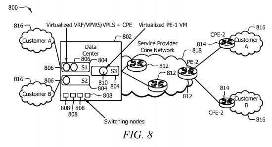
FIG. 9?is a schematic diagram of an embodiment of an NFV system?900?that uses a service decomposition method to virtualize a PE node. The service decomposition method divides a PE device into NFs that correspond to individual network services. In one embodiment, the network services may be provider provisioned virtual private network service functions, such as IP VPN, VPWS, and VPLS, as described in IETF RFC 4026. Each of the network services may be L2 and/or L3 services used to connect to different customer sites. For a service decomposition method, the PE Orchestrator may launch each of the network services on separate virtual containers. As such, the network services are independent of one another and can scale independently as per their requirements without infringing on each other‘s resources. As shown in?FIG. 9, the VPLS site?920?communicates with the Access VPLS VM?906; the IP VPN site?922?communicates with the Access IP VPN VM?908; and the VPWS site?924?communicates with the Access VPWS VM?910. The VPLS site?920, IP VPN site?922, and VPWS site?924?may be customer networks configured to implement VPLS, IP VPN, and VPWS, respectively. The Access VPLS VM?906, Access IP VPN VM?908, and Access VPWS VM?910?may be configured to implement PE network functions using a plurality of NFs, such as OAM, Alarms, OSPF, RIB, FIB, and hardware abstraction layer functions.
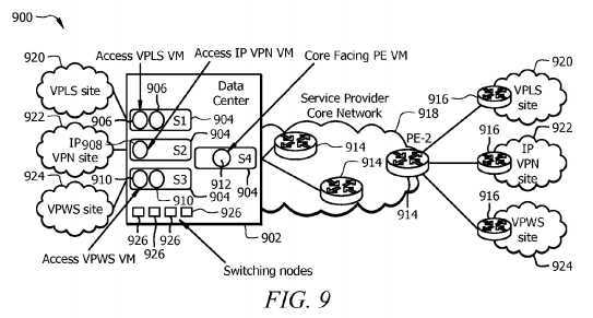
The NNI may be treated as a shared resource that may be implemented in a single Core Facing PE VM?912?or divided into a plurality of Core Facing PE VMs?912. When multiple Core Facing PE VMs?912?are used, each of the Core Facing PE VMs?912?may be coupled to and correspond to one of the network service side VMs. For example, the Access VPLS VM906?may be coupled to a first Core Facing PE VM?912, while the Access IP VPN VM?908?may be coupled to a second Core Facing PE VM?912. The Core Facing PE VM?912?may perform functions substantially similar to the Core Facing PE VM?508as described in?FIG. 5. Data center?902, servers?904, switching nodes?926, non-virtualized PE devices?914, CPE nodes916?and service provider core network?918?are substantially similar to the data center?604, servers?606, switching nodes608, non-virtualized PE devices?612, CPE nodes?602, and service provider core network?616?as described in?FIG. 6, respectively.
FIG. 10?is a flowchart of an embodiment of a method?1000?used to perform an NFV virtualization on a network device. Method?1000?may be implemented within a PE Orchestrator as described in?FIG. 2?and a VNF Manager as described inFIG. 1. Method?1000?starts at block?1002?and receives an instruction to perform an NFV virtualization of a network device. The instruction may originate from a network administrator or operator. Method?1000?may directly receive the instructions from the network administrator or operator or may indirectly receive the instructions from the network administrator via a separate orchestrator, such as Orchestrator?102?in?FIG. 1. Afterwards, method?1000?may then move to block?1004.
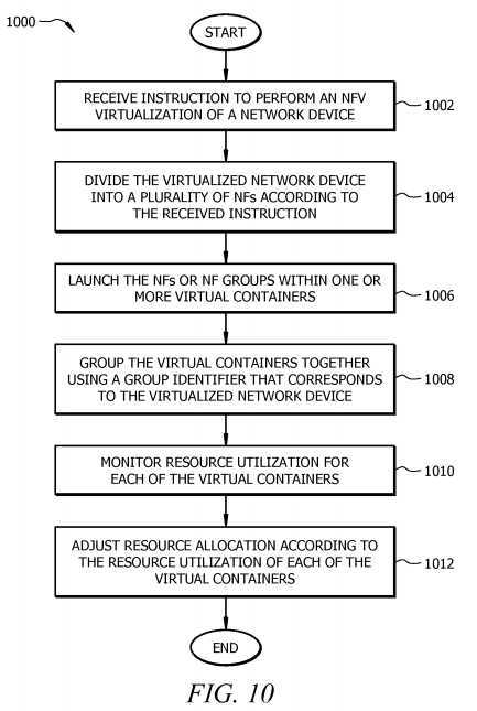
At block?1004, method?1000?may divide the virtualized network device into a plurality of NFs according to the received instructions. Method?1000?may divide the virtualized network device using the absolute decomposition method, network function decomposition method, and/or the service decomposition method. The received instructions originating from the network administrator or operator may determine which method is used to divide the virtualized network device. The NF may correspond to a network function performed by the virtualized network device. Recall that the absolute decomposition method divides the network device into separate device function components that correspond to separate NFs. For the network function decomposition method, the virtualized network device is divided based on network connectivity. For example, method?1000?may divide based on the interfaces (e.g. UNI and NNI) used to connect different networks. The service decomposition method divides the virtualized network device based on the network services, such as IP VPN, VPWS, and VPLS. Once method?1000?completes block?1004, method?1000?may then move to block?1006.
At block?1006, method?1006?may launch the NFs or NF groups within one or more virtual containers. For the absolute decomposition method, each of the NFs may be hosted within one of the virtual containers. Alternatively, method?1006?may launch one or more NFs in a single virtual container when implementing the network function decomposition method and/or the service decomposition method. Method?1000?may then continue to block?1008?to group the virtual containers together using a group identifier that corresponds to the virtualized network device. In one embodiment, the group identifier may be a device identifier used to identify the virtualized network device. Method?1000?may then proceed to block?1010.
At block?1010, method?1000?may monitor the resource utilization for each of the virtual containers. To obtain resource utilization for each of the virtual containers, method?1000?may communicate with other management entities and/or other virtualized network nodes. For example, method?1000?may obtain resource utilization information from the Virtualized Infrastructure Manager?106?and/or the Virtual Machine Manager?204?as described in?FIGS. 1 and 2, respectively. Method1000?may then move to block?1012?to adjust resource allocation according to the resource utilization of each of the virtual containers. Adjusting resource allocation may be implemented in a proactive manner or a reactive manner. In addition, at block?1012, method?1000?may migrate and/or move virtual containers to different servers and/or other hardware resource nodes when the current server and/or hardware resource node is unable to provide the resources needed by the virtual container.
SRC=https://www.google.com/patents/US20140201374
Network Function Virtualization for a Network Device,布布扣,bubuko.com
Network Function Virtualization for a Network Device
标签:des style blog http color os strong io
原文地址:http://www.cnblogs.com/coryxie/p/3866841.html