标签:des style blog http color os io strong
A disk array controller has a function of relocating a plurality of data blocks stored in a disk array. The controller includes a read unit which reads data blocks to be relocated from the disk array, a determining unit which determines whether an error has occurred in the to-be-relocated data block read by the read unit, a write unit which writes the to-be-relocated data block read by the read unit in a relocating destination position on the disk array which corresponds to the to-be-relocated data block if the determining unit determines that the error has not occurred in the to-be-relocated data block, and a unit which sets error information with respect to the relocating destination position if the determining unit determines that the error has occurred in the to-be-relocated data block, the error information causing occurrence of an error in response to read access of the relocating destination position.
This invention relates to a disk array controller and information processing apparatus which control a redundant disk array such as a RAID (Redundant Array of Inexpensive Disks or Redundant Array of Independent Disks).
Recently, in an information processing apparatus such as a server computer and personal computer, a redundant disk array such as RAID has been utilized in order to enhance the disk access speed and protect stored data. In the RAID, some redundancy levels (which are also referred to as RAID levels), for example, RAID0, RAID1, RAID5?are defined.
Most of the RAID controllers have a rebuild function of restoring the state of a disk array in which a fault has occurred into the state set before occurrence of the fault. The rebuild function is a function of restoring the contents of data stored in a disk drive in which a fault has occurred by use of the contents of data stored in another disk drive.
A disk control apparatus having the rebuilt function is disclosed in Jpn. Pat. Appln. KOKAI Publication No. 10-40022.
Further, in the recent RAID controller, it is required to attain not only a function such as a rebuild function of taking measures to prevent occurrence of faults but also a function of changing the redundancy level (RAID level) of the disk array or expanding the storage capacity.
In order to perform the level changing process of changing the redundancy level (RAID level) of the disk array or the capacity expanding process of expanding the storage capacity of the disk array, it is necessary to relocate a data block group stored in the disk array.
However, if a media error occurs in the storage position on the disk array in which one of the data blocks to be relocated is stored, the level changing process or capacity expanding process cannot be performed. In this case, the media error represents an error which prevents data from being correctly read from the disk drive even if read tries are repeatedly made by a preset number of times.
Since the to-be-relocated data block cannot be read from the storage position in which the above error occurs, it becomes impossible to ensure the contents of data in a transfer-destination position to which the to-be-relocated data block is transferred. Therefore, in the level changing process or capacity expanding process, if occurrence of an error is detected at the time of reading the to-be-relocated data block, it is necessary to interrupt the process at this time point. If the process is not interrupted, there occurs a possibility that data of an erroneous value may be transferred from the disk array to a host when a read request is issued by the host with respect to the transfer-destination position to which the data block could not be transferred after the level changing process or capacity expanding process.
According to an aspect of the invention, there is provided a disk array controller which controls a disk array to change a redundancy level of the disk array, comprising a read unit which reads a data block to be relocated from the disk array, a determining unit which determines whether or not an error has occurred in the to-be-relocated data block read by the read unit, a write unit which writes the to-be-relocated data block read by the read unit in a relocating destination position on the disk array corresponding to the to-be-relocated data block if the determining unit determines that the error has not occurred in the to-be-relocated data block, and an error information setting unit configured to set error information with respect to the relocating destination position if the determining unit determines that the error has occurred in the to-be-relocated data block, the error information causing occurrence of an error in response to read access of the relocating destination position.
According to another aspect of the invention, there is provided a disk array controller which controls a disk array to expand storage capacity of the disk array, comprising a read unit which reads a data block to be relocated from the disk array, a determining unit which determines whether or not an error has occurred in the to-be-relocated data block read out by the read unit, a write unit which writes the to-be-relocated data block read by the read unit in a relocating destination position on the disk array corresponding to the to-be-relocated data block if the determining unit determines that the error has not occurred in the to-be-relocated data block, and an error information setting unit configured to set error information with respect to the relocating destination position if the determining unit determines that the error has occurred in the to-be-relocated data block, the error information causing occurrence of an error in response to read access of the relocating destination position.
There will now be described embodiments of this invention with reference to the accompanying drawings.
In?FIG. 1, the configuration of an information processing apparatus according to a first embodiment of this invention is shown. For example, the information processing apparatus is realized as a server computer. The information processing apparatus includes a host (host computer)?10?which executes an operating system and various application programs, a disk array?20?used as an external storage device of the host?10, and a disk array controller?30.
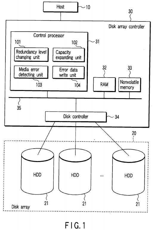
The disk array?20?is a redundant disk array and is realized by use of a plurality of disk drives (hard disk drives [HDDs])?21mounted on the information processing apparatus. The disk array controller?30?controls the disk array?20?in response to a disk access request from the host?10. The disk array controller?30?performs the disk control operation to operate the disk array?20?as a RAID.
For example, the disk array controller?30?supports a plurality of redundancy levels (RAID levels) such as RAID0?(striping), RAID1?(mirroring) and RAID5?(distributed data guarding).
As shown in?FIG. 1, the disk array controller?30?includes a control processor?31, RAM?32, nonvolatile memory?33?and disk controller?34. The control processor?31, RAM?32, nonvolatile memory?33?and disk controller?34?are connected to a bus?35.
The control processor?31?executes a program (firmware) loaded from the nonvolatile memory?33?into the RAM?32. By use of the firmware, in the control processor?31, a redundancy level changing unit?101, capacity expanding unit?102, media error detecting unit?103?and error data write unit?104?are realized as shown in?FIG. 1?as function performing modules.
The redundancy level changing unit?101?performs a redundancy level changing process to change the redundancy level (RAID level) of the disk array?20. The redundancy level changing process can be performed during the operation of the information processing apparatus. In the redundancy level changing process, a process of relocating a plurality of data blocks stored in the disk array?20?is performed based on the relationship between the present redundancy level of the disk array?20?and the target redundancy level of the disk array?20. The relocation process is performed by reading each data block to be relocated from the disk array?20?and copying and supplying the same to a relocating destination position on the disk array?20?to which each data block should be relocated. By the level changing process, the RAID level of the disk array20?can be changed from RAID0?to RAID1?or from RAID0?to RAID5, for example.
The capacity expanding unit?102?performs a capacity expanding process of expanding the storage capacity of the disk array20?by use of an additional disk drive without changing the redundancy level of the disk array?20. The capacity expanding process can also be performed during the operation of the information processing apparatus. In the capacity expanding process, a process of relocating a plurality of data blocks which is already stored in the disk array?20?on an additional disk drive for each stripe unit is performed based on the present redundancy level of the disk array?20?and the number of additional disk drives. The relocation process is performed by reading each data block to be relocated from the disk array20?and copying and supplying the same to a relocating destination position on the disk array?20?to which each data block should be relocated.
The media error detecting unit?103?determines whether or not a media error has occurred at the read time of a to-be-relocated data block. The error data write unit?104?sets error information with respect to the relocating destination position (which is herein-after referred to as a transfer destination position) corresponding to the to-be-relocated data block when occurrence of a media error is detected. The error information is information (error data) which causes occurrence of a media error when read access is made with respect to the transfer destination position. More specifically, the error data write unit?104?writes data and an error-correcting code (ECC) which is not associated with the data as error data in the transfer destination position. Thus, each time the read access is made to the transfer destination position, a media error occurs. Therefore, even if read access is made by the host?10?to the transfer destination position which could not be correctly subjected to a data relocation process, erroneous data can be prevented from being transferred to the host?10.
The error data write unit?104?issues a write long command to the HDD in order to write error data. The write long command is a command which instructs the HDD to store write data containing the error-correcting code as it is. Generally, the HDD causes an ECC generator to generate an ECC based on write data and writes the write data and ECC into a position specified by the write command. Further, when the write command is received, the operation of the ECC generator of the HDD is suppressed. Thus, error data containing data and an ECC which is not associated with the data can be written.
The disk controller?34?controls each of the HDDs configuring the disk array?20?under the control of the control processor?31. The disk controller?34?controls each HDD via an Integrated Drive Electronics (IDE) or Small Computer System Interface (SCSI) interface, for example.
Next, an example of the redundancy level changing operation is explained.
FIG. 2?shows a disk array of RAID0?configured by two HDDs (HDD#0, HDD#1). A plurality of stripes S1, S2, S3?are arranged over the two HDDs (HDD#0, HDD#1).
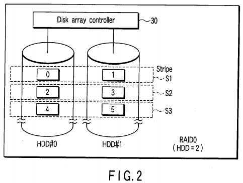
Each stripe is configured by a stripe unit on the HDD#0?and a stripe unit on the HDD#1. Each stripe unit contains at least one data block. In?FIG. 2, a case wherein the number of data blocks contained in each stripe unit is one is shown. The stripe S1?contains a data block of logical block address LBA="0" arranged on the HDD#0?and a data block of logical block address LBA="1" arranged on the HDD#1. Likewise, the stripe S2?contains a data block of logical block address LBA="2" arranged on the HDD#0?and a data block of logical block address LBA="3" arranged on the HDD#1. Further, the stripe S3contains a data block of logical block address LBA="4" arranged on the HDD#0?and a data block of logical block address LBA="5" arranged on the HDD#1.
The stripe is referred to as a stripe group and the stripe unit is referred to as a stripe in some cases.
FIG. 3?shows an example in which one HDD (HDD#2) is additionally provided on the disk array of RAID0?shown in?FIG. 2and the disk array of RAID5?is configured by three HDDs (HDD#0, HDD#1, HDD#2).
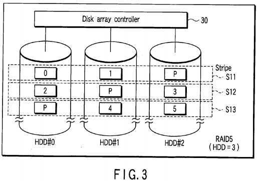
The RAID level of the disk array?20?can be changed from RAID0?to RAID5?by relocating data block groups corresponding to logical block addresses LBA0?to LBA5?stored in the disk array of?FIG. 2?on the three HDDs (HDD#0, HDD#1, HDD#2) as shown in?FIG. 3.
In?FIG. 3, a symbol P indicates information (parity) used to restore a faulty portion which has occurred. The stripe S11contains a data block of logical block address LBA="0" arranged on the HDD#0, a data block of logical block address LBA="1" arranged on the HDD#1?and a parity P arranged on the HDD#2. The parity P of the stripe S11?is generated based on the two data blocks (LBA="0", LBA="1") of the stripe S11. The stripe S12?contains a data block of logical block address LBA="2" arranged on the HDD#0, a parity P arranged on the HDD#1?and a data block of logical block address LBA="3" arranged on the HDD#2. The parity P of the stripe S12?is generated based on the two data blocks (LBA="2", LBA="3") of the stripe S12. Further, the stripe S13?contains a parity P arranged on the HDD#0, a data block of logical block address LBA="4" arranged on the HDD#1?and a data block of logical block address LBA="5" arranged on the HDD#2. The parity P of the stripe S13?is generated based on the two data blocks (LBA="4", LBA="5") of the stripe S13.
RAID0?can be configured in principle on one HDD as shown in?FIG. 4. In?FIG. 4, each stripe unit is configured by two data blocks whose logical block addresses are successive.
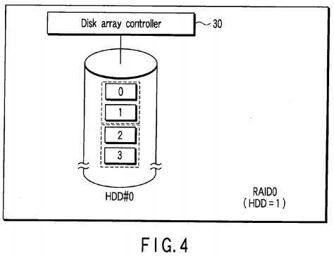
FIG. 5?shows an example in which one HDD (HDD#1) is additionally provided on the disk array of RAID0?shown in?FIG. 4and the disk array of RAID1?is configured by two HDDs (HDD#0, HDD#1).
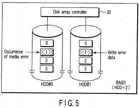
The RAID level can be changed from RAID0?to RAID1?by copying and relocating data block groups corresponding to logical block addresses LBA0?to LBA3?stored in the HDD#0?of?FIG. 4?on the HDD#2?as shown in?FIG. 5.
Thus, in the redundancy level changing process, the data relocation process is performed for each of the data blocks.
If a media error does not occur at the read time of the data block to be relocated, the to-be-relocated data block is written into the transfer destination position as usual. The transfer destination position is a storage position on the disk array to which a logical block address corresponding to the to-be-relocated data block is newly allocated. Further, if a media error occurs at the read time of the to-be-relocated data block, the error data is written into the transfer destination position.
FIG. 6?shows an example of the configuration of the redundancy level changing unit?101.
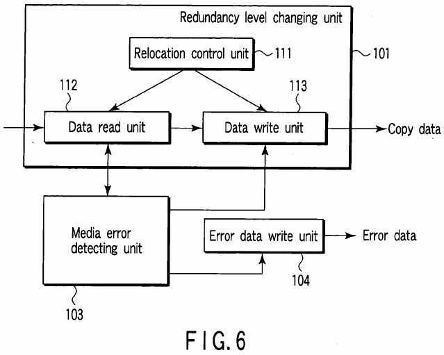
The redundancy level changing unit?101?includes a relocation control unit?111, data read unit?112?and data write unit?113. The relocation control unit?111?determines data block groups to be relocated and the transfer destination positions of the to-be-relocated data block groups based on the relation between the present redundancy level of the disk array?20?and the target redundancy level of the disk array?20. The data read unit?112?reads a to-be-relocated data block from the disk array20?via the disk controller?34?under the control of the relocation control unit?111. The data write unit?113?writes the to-be-relocated data block read by the data read unit?112?in the transfer destination position on the disk array?20?via the disk controller?34?under the control of the relocation control unit?111.
The media error detecting unit?103?detects occurrence of a media error by monitoring success/failure of the read operation via communication with the data read unit?112. If occurrence of a media error is detected, the media error detecting unit103?inhibits the operation of the data write unit?113?and triggers the error data write unit?104.
Next, the concrete procedure of the redundancy level (RAID level) changing process is explained with reference to the flowchart of?FIG. 7. In this case, a case wherein the redundancy level is changed from RAID0?of?FIG. 4?to RAID1?of?FIG. 5is explained as an example.
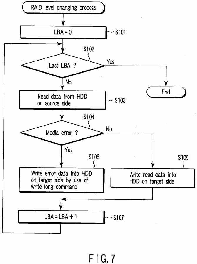
First, the redundancy level changing unit?101?sets a value of the logical block address LBA to an initial value "0" (step S101). Then, the redundancy level changing unit?101?determines whether or not the value of the logical block address LBA exceeds a last logical block address LBA (Last LBA) allocated to the HDD#0?of?FIG. 4?(step S102) and repeatedly performs the following process until the value of the logical block address LBA exceeds the last logical block address LBA.
The redundancy level changing unit?101?reads a to-be-relocated data block specified by the present logical block address LBA (LBA=0) from the HDD#0?(source side HDD) (step S103). The media error detecting unit?103?determines whether or not a media error has occurred in the read operation (step S104).
If occurrence of a media error is not detected, that is, if a to-be-relocated data block specified by the present logical block address LBA (LBA=0) can be correctly read from the HDD#0?(source side HDD) ("NO" in step S104), the redundancy level changing unit?101?writes the to-be-relocated data block read out in step S103?into a transfer destination position on the HDD#1?(target side HDD) corresponding to the to-be-relocated data block (step S105). The transfer destination position is a storage position on the HDD#1?(target side HDD) to which the logical block address LBA (LBA=0) is allocated. Thus, the data block of the source side HDD specified by the present LBA is copied in the storage position on the target side HDD specified by the above LBA.
On the other hand, if occurrence of a media error is detected, that is, if a to-be-relocated data block specified by the present logical block address LBA (LBA=0) cannot be correctly read from the HDD#0?(source side HDD) ("YES" in step S104), the redundancy level changing unit?101?writes error data by use of a write long command in a transfer destination position on the HDD#1?(target side HDD) corresponding to the to-be-relocated data block which cannot be read, that is, in a storage position on the target side HDD specified by the present LBA (LBA=0) (step S106).
Next, the redundancy level changing unit?101?returns the process to step S102?after the present logical block address LBA is increased by +1 (step S107). The RAID level of the disk array?20?is changed from RAID0?to RAID1?by repeatedly performing the process of steps S102?to S107.
In this case, all of the data blocks are dealt with as to-be-relocated data blocks in order to make a level change from RAID0?to RAID1. However, generally, it is only necessary to relocate only a target data block group which is required to be relocated in order to make a level change. That is, the redundancy level changing unit?101?determines logical block addresses of data blocks (transfer-source blocks) to be relocated and transfer destination positions (transfer destination blocks) corresponding to the logical block addresses based on the number of HDDs and RAID levels of the disk array?20before level-changing and the number of HDDs and RAID levels of the disk array?20?after level-changing which are specified by the host?10. Then, the redundancy level changing unit?101?performs the process shown by the flowchart of?FIG. 8?for each transfer-source block.
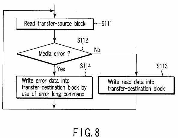
That is, the redundancy level changing unit?101?first reads a transfer-source block from the disk array?20?(step S111). If a media error does not occur in the read operation ("NO" in step S112), the redundancy level changing unit?101?writes the readout transfer-source block into a transfer-destination block corresponding to the transfer-source block (step S113). On the other hand, if a media error occurs in the read operation ("YES" in step S112), the error data write unit?104?writes error data in the transfer-destination block (step S114).
The transfer-source block in which a media error has occurred in the read operation may be used as a transfer-destination block for a different to-be-relocated data block in some cases. In this case, if the different to-be-relocated data block cannot be correctly written into the transfer-destination block, error data is also written into the transfer-destination block.
Next, the operation for reading data from the disk array?20?whose RAID level is changed is explained with reference to the flowchart of?FIG. 9.
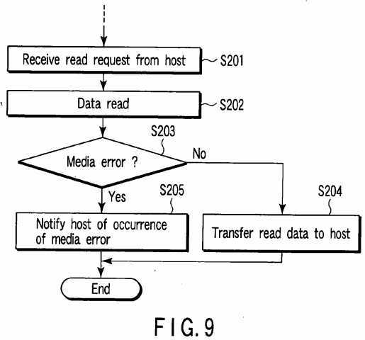
When the control processor?31?receives a read request from a file system or application program executed by the host?10(step S201), it reads a data block specified by the logical block address contained in the read request from the disk array20?(step S202). The control processor?31?determines whether or not a media error has occurred in the read operation of step S202?(step S203). If a media error does not occur ("NO" in step S203), the control processor?31?transfers a data block read from the disk array?20?to the host?10?(step S204). If a media error has occurred ("YES" in step S203), the control processor?31?notifies the host?10?of occurrence of the media error (step S205). Since a media error occurs without fail when a read request is made from the host?10?with respect to a block in which error data is written, erroneous data can be prevented from being transferred to the host?10.
Next, an example of the capacity expanding operation is explained.
FIG. 10?shows a disk array of RAID0?configured by two HDDs (HDD#0, HDD#1). In?FIG. 10, a case wherein the number of data blocks contained in each stripe unit is one is shown.?FIG. 11?shows an example in which one HDD (HDD#2) is additionally provided to the disk array of RAID0?of?FIG. 10?to configure the disk array of RAID0?by three HDDs (HDD#0, HDD#1, HDD#2). The storage capacity of the disk array can be expanded without changing the RAID level by relocating the data block groups corresponding to the logical block addresses LBA0?to LBA5?stored in the disk array of?FIG. 10?into the three HDDs (HDD#0, HDD#1, HDD#2) as shown in?FIG. 11?for each stripe unit.
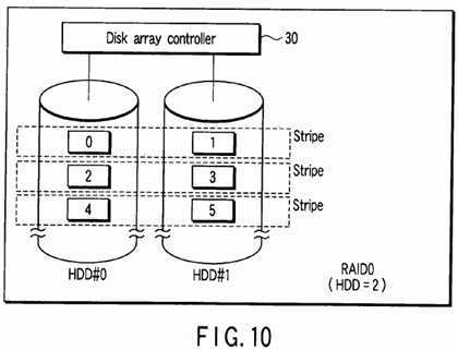
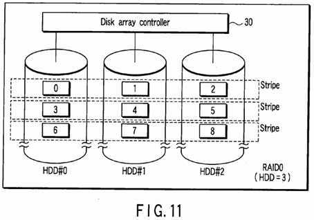
FIG. 12?shows a disk array of RAID0?configured on one HDD (HDD#0). Each stripe unit normally contains two or more data blocks whose logical block addresses are successive.
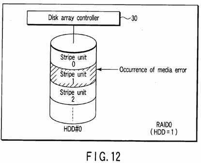
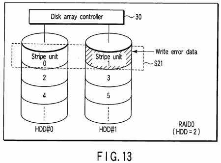
FIG. 13?shows an example in which one HDD (HDD#1) is additionally provided in the disk array of RAID0?of?FIG. 12?to configure a disk array of RAID0?by two HDDs (HDD#0, HDD#1). The data block groups stored in the disk array of?FIG. 12are relocated in the two HDDs (HDD#0, HDD#1) as shown in?FIG. 13?for each stripe unit. In?FIG. 13, for example, one stripe S21?is configured by two stripe units?0,?1?of?FIG. 12?whose logical block addresses are successive.
Thus, in the capacity expanding process, the data block groups are relocated for each stripe unit.
If a media error does not occur at the read time of the to-be-relocated data block, the to-be-relocated data block is written into the transfer destination position as usual. The transfer destination position is a storage position on the disk array to which a logical block address corresponding to the to-be-relocated data block is newly allocated. On the other hand, if a media error has occurred at the read time of the to-be-relocated data block, the above error data is written into the transfer destination position.
FIG. 14?shows an example of the capacity expanding unit?102.
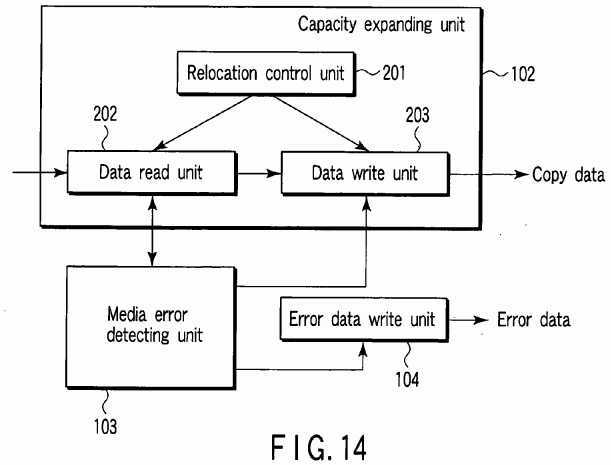
The capacity expanding unit?102?includes a relocation control unit?201, data read unit?202?and data write unit?203. The relocation control unit?201?determines to-be-relocated data block groups and transfer destination positions of the respective data block groups based on the present redundancy level of the disk array?20?and the number of additional disk drives. The data read unit?202?reads a to-be-relocated data block from the disk array?20?via the disk controller?34?under the control of the relocation control unit?201. The data write unit?203?writes the to-be-relocated data block read by the data read unit?202into the transfer destination position on the disk array?20?via the disk controller?34?under the control of the relocation control unit?201.
The media error detecting unit?103?detects occurrence of a media error by monitoring success/failure of the read operation via communication with the data read unit?202. When detecting occurrence of the media error, the media error detecting unit103?inhibits the operation of the data write unit?203?and triggers the error data write unit?104.
Next, the procedure of the capacity expanding process is explained with reference to the flowchart of?FIG. 15.
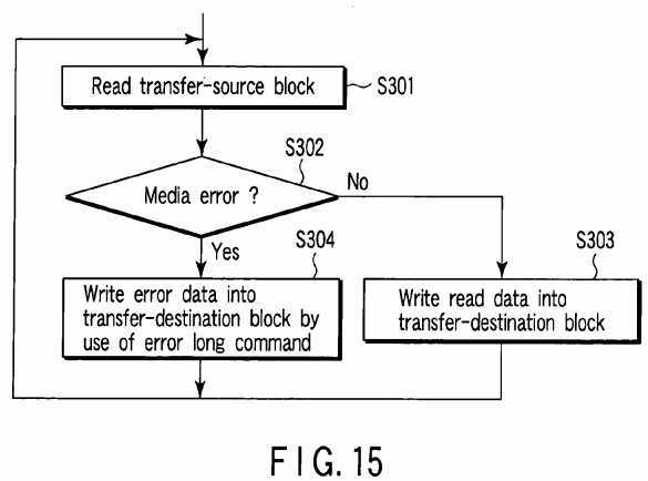
The capacity expanding unit?102?determines logical block addresses of to-be-relocated data blocks (transfer-source blocks) and transfer destination positions (transfer-destination blocks) corresponding to the logical block addresses based on the present redundancy level of the disk array?20?and the number of additional disk drives. Then, the capacity expanding unit102?performs a process shown by the flowchart of?FIG. 15?for each transfer-source block.
That is, the capacity expanding unit?102?first reads a transfer-source block from the disk array?20?(step S301). If no media error occurs in the read operation ("NO" in step S302), the capacity expanding unit?102?writes the read transfer-source block into a transfer-destination block corresponding to the transfer-source block (step S303). If a media error occurs in the read operation of the step S301?("YES" in step S302), the error data write unit?104?writes error data into the transfer-destination block by use of a write long command (step S304).
Also, in the capacity expanding process, a transfer-source block in which a media error occurs in the read operation may be used as a transfer-destination block for a different to-be-relocated data block in some cases. In this case, if the different to-be-relocated data block cannot be correctly written into the transfer-destination block, error data is also written into the transfer-destination block.
The data read operation after expanding the capacity of the disk array?20?is performed according to the same procedure as that shown in?FIG. 9.
As described above, in each of the redundancy level changing process and capacity expanding process of the present embodiment, if an error such as a media error occurs at the read time of the to-be-relocated data block, error data is written into a transfer-destination block corresponding to the to-be-relocated data block. As a result, even when an error such as a media error occurs during the level changing process and capacity expanding process, the level changing process and capacity expanding process can be continuously performed without interruption.
FIG. 16?is a block diagram showing the configuration of an information processing apparatus according to a second embodiment of this invention. In?FIG. 16, the same portions as those of?FIG. 1?are denoted by the same reference numbers.
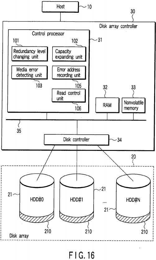
In the second embodiment, a control processor?31?of a disk array controller?30?has an error address recording unit?105?and read control unit?106?instead of the error data write unit?104?of?FIG. 1. The error address recording unit?105?stores a logical block address LBA which indicates a transfer destination position corresponding to a to-be-relocated data block as an error address into a nonvolatile memory?33?or a reserved region?210?of a disk array?20?when a media error occurs at the read time of the to-be-relocated data block. A logical block address LBA corresponding to each of the to-be-relocated data blocks before the redundancy level changing process or before the capacity expanding process is used as a logical block address LBA of the transfer destination position after the redundancy level changing process or after the capacity expanding process. Therefore, the error address recording unit?105?may store a logical block address of the to-be-relocated data block as an error address when a media error occurs at the read time of the to-be-relocated data block.
After the redundancy level changing process or after the capacity expanding process, the read control unit?106?determines whether or not a logical block address LBA contained in a read access request issued from a file system or application program executed by a host?10?is stored as an error address. If the error address is stored, the read control unit?106generates a media error.
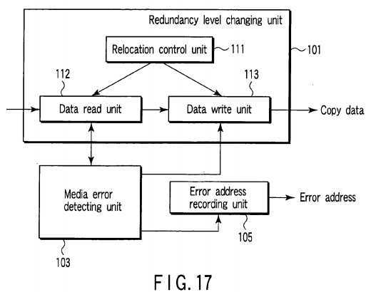
FIG. 17?shows the relationship between the redundancy level changing unit?101, error address recording unit?105?and media error detecting unit?103. Like the first embodiment, the redundancy level changing unit?101?includes a relocation control unit111, data read unit?112?and data write unit?113. The media error detecting unit?103?detects occurrence of a media error by monitoring success/failure of the read operation via communication with the data read unit?112. When detecting occurrence of a media error, the media error detecting unit?103?inhibits the operation of the data write unit?113?and triggers the error address recording unit?105. The error address recording unit?105?stores a logical block address corresponding to a to-be-relocated data block in which occurrence of the media error is detected by the media error detecting unit?103?as an error address.
Next, the procedure of the redundancy level changing process is explained with reference to the flowchart of?FIG. 18. As described above, the redundancy level changing unit?101?determines logical block addresses of to-be-relocated data blocks (transfer-source blocks) and transfer destination positions (transfer-destination blocks) corresponding to the logical block addresses based on the number of HDDs and the RAID level of the disk array?20?before level-changing, the number of HDDs and the RAID level of the disk array?20?after level-changing specified by the host?10. Then, the redundancy level changing unit?101?performs the process shown by the flowchart of?FIG. 18?for each transfer-source block.
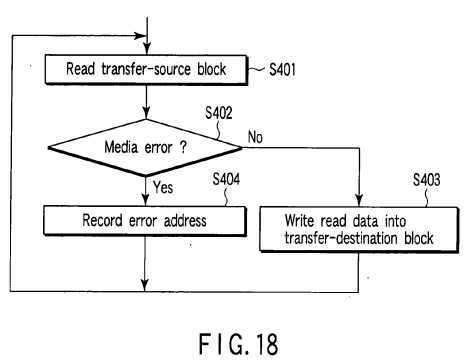
That is, the redundancy level changing unit?101?first reads a transfer-source block from the disk array?20?(step S401). If no media error occurs in the read operation ("NO" in step S402), the redundancy level changing unit?101?writes the read transfer-source block into a transfer-destination block corresponding to the transfer-source block (step S403). If a media error occurs in the read operation of the step S401?("YES" in step S402), the error address recording unit?105?stores a logical block address LBA corresponding to the transfer-source block in which the media error has occurred as an error address (step S404).
As described above, a transfer-source block in which a media error occurs in the read operation for a certain to-be-relocated data block may be used as a transfer-destination block for a different to-be-relocated data block in some cases. In this case, if the different to-be-relocated data block cannot be correctly written into the transfer-destination block, a logical block address LBA to be newly allocated to the transfer-destination block is also stored as an error address.
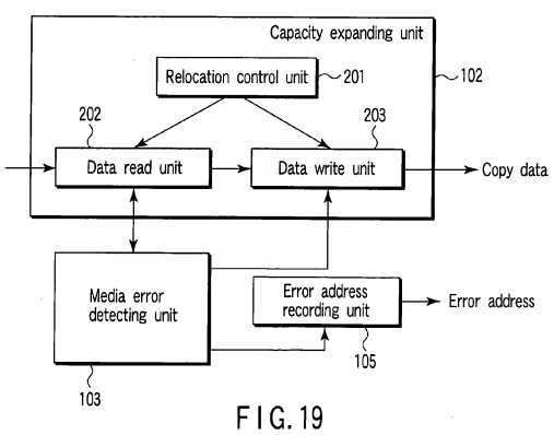
FIG. 19?shows the relationship between a capacity expanding unit?102, error address recording unit?105?and media error detecting unit?103. Like the first embodiment, the capacity expanding unit?102?includes a relocation control unit?201, data read unit?202?and data write unit?203. The media error detecting unit?103?detects occurrence of a media error by monitoring success/failure of the read operation via communication with the data read unit?202. When detecting occurrence of a media error, the media error detecting unit?103?inhibits the operation of the data write unit?203?and triggers the error address recording unit?105. The error address recording unit?105?stores a logical block address corresponding to a to-be-relocated data block in which occurrence of the media error is detected by the media error detecting unit?103?as an error address.
Next, the procedure of the capacity expanding process is explained with reference to the flowchart of?FIG. 20.
As described above, the capacity expanding unit?102?determines logical block addresses of to-be-relocated data blocks (transfer-source blocks) and transfer destination positions (transfer-destination blocks) corresponding to the logical block addresses based on the present redundancy level of the disk array?20?and the number of additional disk drives. Then, the capacity expanding unit?102?performs the process shown by the flowchart of?FIG. 20?for each transfer-source block.
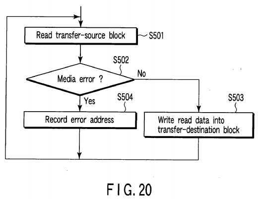
That is, the capacity expanding unit?102?first reads a transfer-source block from the disk array?20?(step S501). If no media error occurs in the read operation ("NO" in step S502), the capacity expanding unit?102?writes the read transfer-source block into a transfer-destination block corresponding to the transfer-source block (step S503). If a media error occurs in the read operation of the step S501?("YES" in step S502), the error address recording unit?105?stores a logical block address LBA corresponding to the transfer-source block in which the media error has occurred as an error address (step S504).
As described above, in the capacity expanding process, a transfer-source block in which a media error occurs in the read operation for a certain to-be-relocated data block may be used as a transfer-destination block for a different to-be-relocated data block in some cases. In this case, if the different to-be-relocated data block cannot be correctly written into the transfer-destination block, a logical block address LBA to be newly allocated to the transfer-destination block is also stored as an error address.
Next, the data read operation after changing the RAID level of the disk array?20?or after expanding the capacity is explained with reference to the flowchart of?FIG. 21.
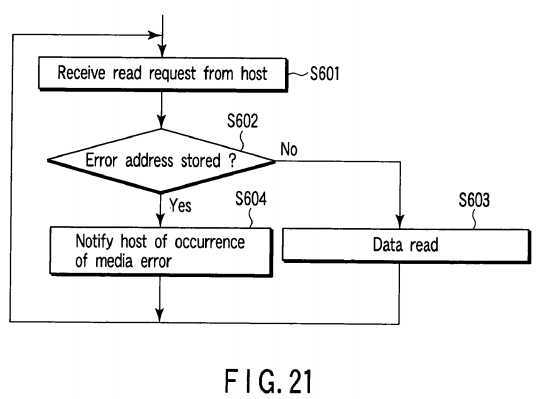
When the control processor?31?receives a read access request transmitted from a file system or application program executed by the host?10?(step S601), it causes the read control unit?106?to determine whether or not a logical block address contained in the read access request is stored as an error address (step S602). If the logical block address contained in the read access request is not stored as the error address ("NO" in step S602), the control processor?31reads a data block specified by the logical block address contained in the read access request from the disk array?20?(step S602). If the logical block address contained in the read access request is stored as the error address ("YES" in step S602), the control processor?31?notifies the host?10?of occurrence of a media error (step S604). Since a media error always occurs when a read request is made with respect to the logical block address stored as an error address, erroneous data can be prevented from being transferred to the host?10. Therefore, in the second embodiment, it is not necessary for each of the HDDs which configure the disk array?20?to support the write long command.
In the so-called software RAID which controls the disk array?20?in a software manner, the redundancy level changing process and capacity expanding process in each of the above embodiments can be performed by use of a RAID control program executed by the host?10.
Further, in each of the above embodiments, the process performed in a case wherein a media error occurs in the to-be-relocated data block is explained, but the process is not limited to a case of occurrence of the media error. For example, when an error such as a read error which prevents the data block from being read from the to-be-relocated data block occurs, the same process can be applied.
Additional advantages and modifications will readily occur to those skilled in the art. Therefore, the invention in its broader aspects is not limited to the specific details and representative embodiments shown and described herein. Accordingly, various modifications may be made without departing from the spirit or scope of the general inventive concept as defined by the appended claims and their equivalents.
SRC=https://www.google.com.hk/patents/US20050229033
Disk array controller and information processing apparatus,布布扣,bubuko.com
Disk array controller and information processing apparatus
标签:des style blog http color os io strong
原文地址:http://www.cnblogs.com/coryxie/p/3896072.html