标签:format block error receive ber strong get via soc
Bringing up the Avnet MicroZed with Vivado
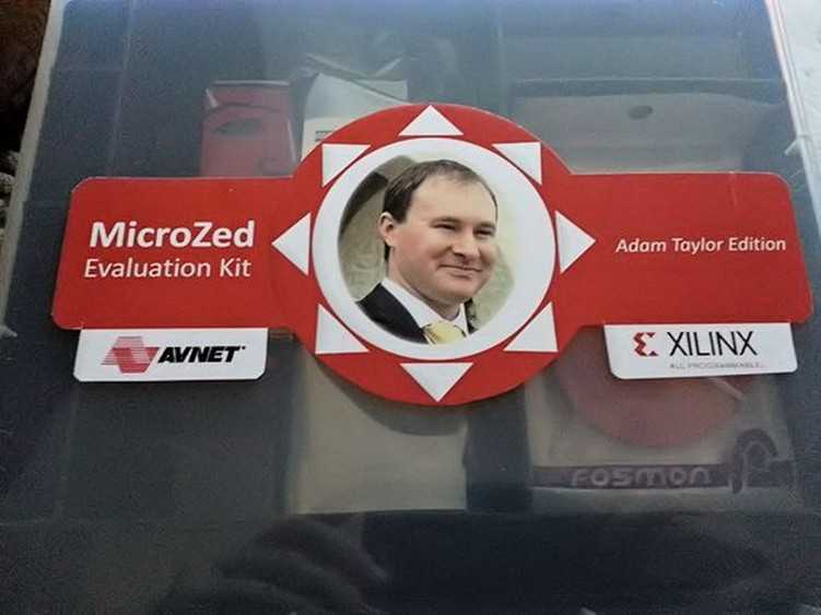
I recently received the Adam Taylor Edition of Avnet‘s Zynq-based MicroZed board, which was sent by the very kind people at Xilinx. I have been writing about the ZedBoard for a while now over on All Programmable Planet. For the original ZedBoard, I used the more traditional PlanAhead, Xilinx Platform Studio, and Software Design Kit (SDK) flow. With that in mind, I decided that for the MicroZed I would implement the system using the Xilinx Vivado Design Suite, which turned out to be surprisingly easy. My aim is to progress with the MicroZed in a similar manner to the ZedBoard: looking at creating the system, using the on-chip XADC, boot-loading the MicroZed, adding my own peripheral, and finally adding an operating system. I expect this will progress rapidly expect due to my familiarity with the ZedBoard.
The first step is to download the MicroZed board definition and configuration, which are available at http://www.zedboard.org/documentation/1519. The first file to download is the MicroZed board definition file, which should be extracted to your Xilinx implementation directory. In my case, the directory is loacated at C:\Xilinx\Vivado\2013.2\data\boards\zynq. This file provides the Vivado Design Suite with MicroZed configuration information. The second file you‘ll need is a TCL file containing the necessary preset information for the MicroZed. We‘ll run this TCL file once we have created a project.
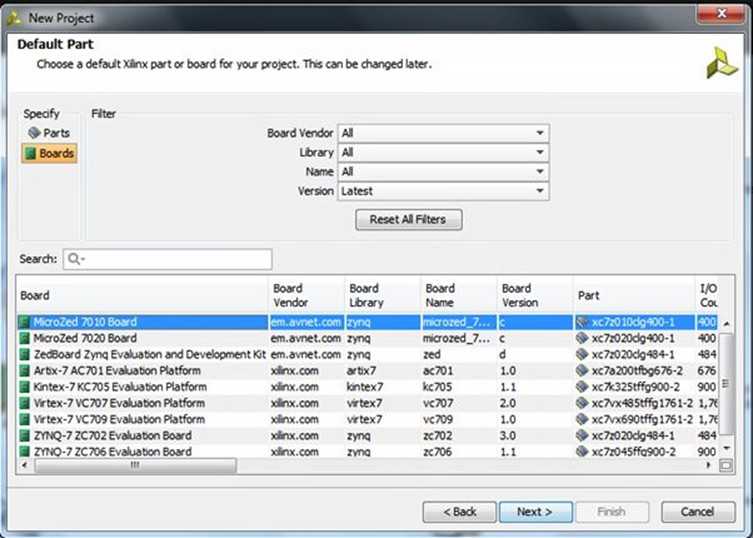
After starting Vivado, the first step is to create a new project. My first MicroZed project will be an RTL project and will not contain any initial source code. The next step is to select the MicroZed 7010 board as a default target using the definition file just downloaded.
Now that the project is created, we need to add the Zynq SoC‘s processing system (PS). The best way to do this is to create a new block diagram and add in the Zynq PS from the IP library in Vivado. We can then create a block diagram by selecting the option under the flow-control window on the left-hand side of the Vivado screen.

With the PS now added to the block diagram, we need to define the system. We could do this by hand (as would be the case for a custom board). Rather helpfully, the MicroZed people have created a TCL file that defines the MicroZed system. It‘s the preset file we downloaded at the start. This TCL file defines the PS bank voltages, buses, clocks, fabric clocks, DDR3 settings, external peripherals, and the MIO configuration.
Note: Remember to use linux style forward separators:
"C:/Users/Adam/Downloads/MicroZed_PS_properties_v02/MicroZed_PS_properties_v02.tcl"

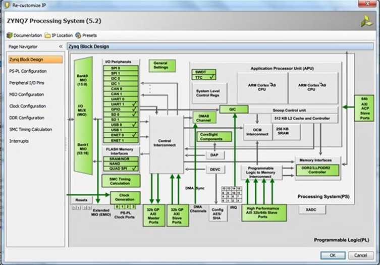
Having applied this file, we then double click on the system and we see the Zynq PS design. Notice that this definition ties up with the capabilities of the MicroZed board‘s Ethernet, USB, DDR3 etc.
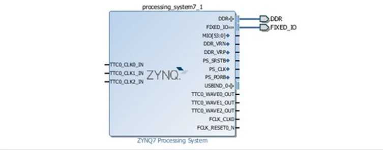
Once we‘re happy with the PS configuration, we need to declare the system‘s external I/O. In this case, we want to declare the DDR and the fixed I/O. Within the Zynq PS, the fixed I/O includes the MIO, clocks, and resets along with the DDR3 reference voltages. As these are fixed, no UCF file is required because we are not working with the programmable logic (PL) side of the Zynq. We will need to create UCFs later when we use the Zynq‘s PL side.
To add these external I/O declarations, you click on the "run design automation" option that appears at the top of the diagram. This will generate a warning. Clicking on "OK" allows you to proceed and you will then see outputs added to the fixed IO and the DDR within the block diagram.
Now we‘re nearly ready to proceed to build the system. However, we must first validate the design to ensure that it is valid and contains no errors by selecting the "validate design" button on the left side of the Vivado screen.

Having created a valid block diagram we will want to save this before we proceed. Once you have saved the design, the next step is to generate the files needed to implement the system, starting with the creation of the HDL wrapper. But first, we need to determine which language we‘re going to work in (VHDL or Verilog). We select the HDL via the Tools->Project Settings Menu.
Once we‘ve selected our preferred language, we right click on the uzed.bd file under "sources" and select "Create HDL Wrapper" to generate the wrapper.
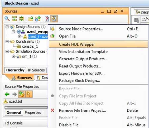
We can also create the necessary synthesis and place-and-route files by selecting the "Generate Output Products…" option from the same menu that we used to generate the HDL wrapper.
Once these files have been created, it‘s time to generate the bitstream by selecting the "Generate Bitstream" option in the flow navigator on the left of the Vivado screen. When the bitstream generation completes, you will see:
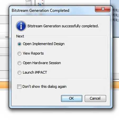
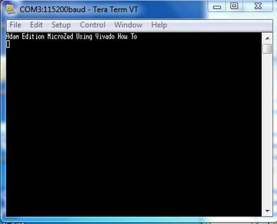
With the bitstream created, we then export the data into SDK. Then we‘re ready to write the software to run on the MicroZed‘s Zynq SoC. I‘ll discuss this process in my next blog, but a sneak peak of where we are headed appears below.
I spent an afternoon bringing up the MicroZed and really enjoyed the experience. My next blog post will wrap up SDK project creation and boot loading with the MicroZed.
Note: Please do not be concerned if you see an error in Vivado version 2013.2 which reports "Failed to get a license:Internal Bit stream." This is a bug in the current version. You can check in the implementation log to make sure that the license was in fact obtained.
Bringing up the Avnet MicroZed with Vivado
标签:format block error receive ber strong get via soc
原文地址:http://www.cnblogs.com/layout/p/7452929.html