标签:cto 翻译 and tar init 自定义 odi shader 分类
clip函数可以用来切割mesh
clip(var); var 的值小于0时就会被切割
表面着色器
其实就是生成了定点片元着色器,相当于一种包装和简化吧
标准的填充结构
struct SurfaceOutput
{
    fixed3 Albedo;  // diffuse color
    fixed3 Normal;  // tangent space normal, if written
    fixed3 Emission;
    half Specular;  // specular power in 0..1 range
    fixed Gloss;    // specular intensity
    fixed Alpha;    // alpha for transparencies
};
其他两种输出结构
struct SurfaceOutputStandard
{
    fixed3 Albedo;      // base (diffuse or specular) color
    fixed3 Normal;      // tangent space normal, if written
    half3 Emission;
    half Metallic;      // 0=non-metal, 1=metal
    half Smoothness;    // 0=rough, 1=smooth
    half Occlusion;     // occlusion (default 1)
    fixed Alpha;        // alpha for transparencies
};
struct SurfaceOutputStandardSpecular
{
    fixed3 Albedo;      // diffuse color
    fixed3 Specular;    // specular color
    fixed3 Normal;      // tangent space normal, if written
    half3 Emission;    //我测试以后觉得这个Emission应该是单元数据啊。。。。???
    half Smoothness;    // 0=rough, 1=smooth
    half Occlusion;     // occlusion (default 1)
    fixed Alpha;        // alpha for transparencies
};
表面着色器放在 PROGRAM CG ...ENDCG区域中,并且不需要放在PASS中,直接放在subshader里
必须用#pragma surface...来说明这是一个表面着色器
大概的格式是这样
#pragma surface surfaceFunction lightModel [optionalparams]
surfaceFunction的基本格式:
void surfaceFunction(Input in,inout SurfaceOutput o)
LightModel的分类:
Lambert,BlinnPhong:这两个对应的是输出结构是SurfaceOutput
Standard对应的是SurfaceStandard
StandardSpecular对应的是SurfaceStandardSpecular
其他的设置我们暂时不去了解,先来了解一下输入结构Input的相关语义
float3 viewDir: 包含了观察方向,用来计算视差效果,或者是边缘光之类的
float4 以COLOR语义填充:包括了每个定点的差值颜色
float3 screenPos:包含了用于反射或者屏幕空间特效的屏幕空间坐标,需要注意的是这并不适用于GrabPass,你需要你自己计算UV使用ComputeGrabScreenPos函数
float3 worldPos:包括了世界空间坐标
float3 worldRefl:包含了世界空间的反射向量(如果这个表面着色器没有写o.Normal这个结构)可以看Reflect-Diffuse着色器作为例子
float3 worldNormal:包含了世界空间法线向量(如果这个表面着色器没有写o.Normal这个结构)
float3 worldRef1;INTERNAL_DATA:包含了世界空间反射向量(当表面着色器写入到o.Normal结构以后)。要使反射向量基于每个像素点的法线贴图,请使用WorldReflectionVector(IN,o.Normal),可以看Reflect-Bumped shader作为例子
float3 worldNormal;INTERNAL_DATA:包含了世界空间法线向量(当表面着色器写入到o.Normal结构以后)。要使得法线向量基于每个的像素点的法线贴图,请使用WorldNormalVector(IN,o.Normal)
o.Normal在填充的时候一定要用UnpackNormal来解tex2D NormalMap之后的结果
o.Normal =UnpackNormal( tex2D(_NormalTex, IN.uv_NormalTex));
边缘光照的编写:
首先先声明边缘光照的参数
        _RimColor("边缘光照",Color) = (0,0,0,1)
        _RimPow("边缘光照参数",Range(0.5,8)) = 1
然后输入结构里需要用到viewDIr
    struct Input {
          float2 uv_MainTex;
          float2 uv_BumpMap;
          float3 viewDir;
      };
然后需要做一些数学运算
(saturate可以将值限制在0到1之间)
half rim=saturate(dot(o.Normal,nomalize(IN.viewDir)));
o.Emission=_RimColor*pow(rim,_RimPow);
然后就有一个边缘发光的效果了
屏幕空间的细节图
这个比较有趣,可能可以用来做一些有趣的效果
先上效果图

这个细节贴图是不会随着你的观察方向变化的,有点像平面的GUI那种感觉
具体实现
其实就是不适用默认的uv_Detail,用一个有关屏幕坐标计算出来的UV来代替这个uv
代码如下
//输入结构
struct Input{
    float4 screenPos;
};

//surf里的代码(就不写函数结构了)
float2 screenUV = IN.screenPos.xy /IN.screenPos.w;
screenUV *= float2(1, 1);//这里可以用来定义材质上出现多少张这个贴图
o.Albedo *= tex2D(_Detail, screenUV).rgb * 2;
这个目前还没有体会到作用,基本是用来做反射用的吧大概。主要是能在Asset里面把Texture设为Cube然后就可以用了。
然后先要在输入结构加一个worldRefl
struct Input{
 float3 worldRefl; INTERNAL_DATA
}
SamplerCUBE _Cube;
然后在surf函数里面把计算出来的值传给texCUBE这个函数然后赋值给Emission就可以
o.Emission = texCUBE (_Cube, IN.worldRefl).rgb;
世界空间坐标的切割
首先要使用到的,就是clip这个函数
对clip的参数取值,如果参数的任意一个分量小于0就剪切掉
比如clip(float3(0.1,0.2,0.3)-0.11)是会被剪切掉的
然后这个例子呢,还用了一个函数frac(),这个函数可以截取一个数的小数部分
所以这样写就好
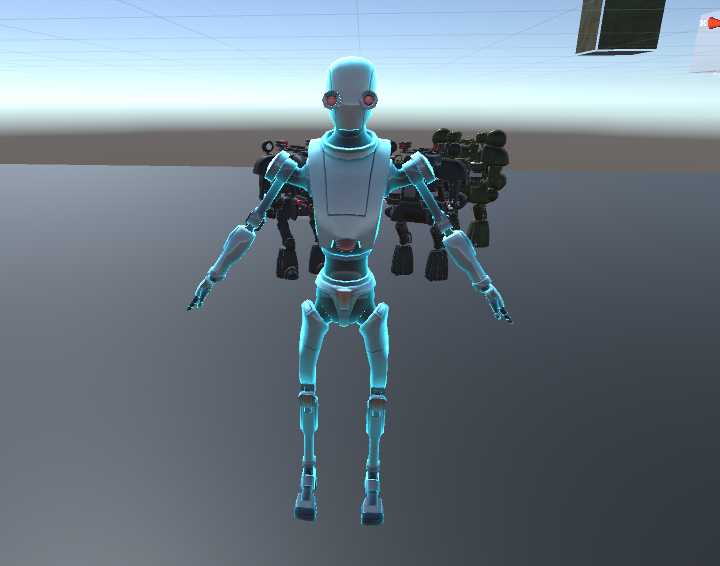
clip(frac((IN.worldPos.y ) * 50) - 0.5);
50那个参数越大 切的段数越多
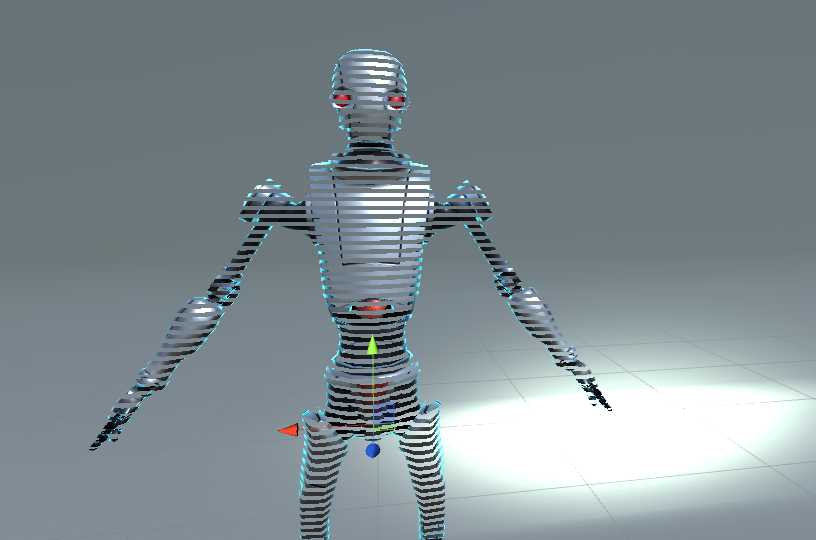 这是50的
这是50的
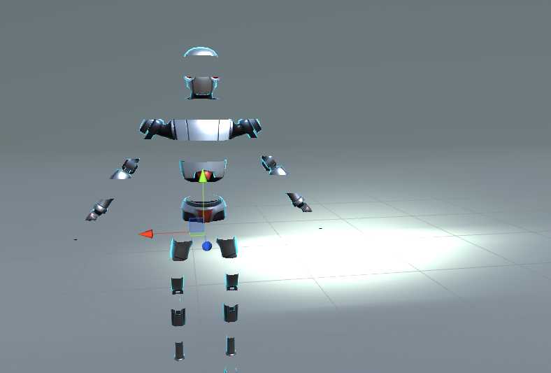 这是5的
这是5的
简单的数学运算便可以得到,这个很有趣
也可以用某些贴图来做运算,可以指定渐变消失的方式之类的
clip(tex2D(_ClipFogTex, IN.uv_ClipFogTex).rgb - _ClipPara);
然后只需要调整_ClipPara就可以改变了
终于可以用顶点着色器啦!
其实就是在定点着色器里针对每一个顶点做一点手脚
      void surf (Input IN, inout SurfaceOutput o) {
          o.Albedo = tex2D (_MainTex, IN.uv_MainTex).rgb;
      }
别忘记声明 vertex:vert
使用顶点着色器函数,能够在定点着色器计算一些数据,这些数据可以以每个像素传递到表面着色器中。与此同时,编辑器指令 vertex:functionname使用,但是这个函数应该有两个参数才对:inout appdata_full 和out Input。你可以用任何的输入成员(只要不是这里的内建值)来填充。
注意:用此方法的自定义输入成员必须不能以“uv”开头
这个例子就是用来定义一个自定义的float3 customColor成员的,它会在顶点函数中进行计算
 Shader "Example/Custom Vertex Data" {
    Properties {
      _MainTex ("Texture", 2D) = "white" {}
    }
    SubShader {
      Tags { "RenderType" = "Opaque" }
      CGPROGRAM
      #pragma surface surf Lambert vertex:vert
      struct Input {
          float2 uv_MainTex;
          float3 customColor;
      };
      void vert (inout appdata_full v, out Input o) {
          UNITY_INITIALIZE_OUTPUT(Input,o);
          o.customColor = abs(v.normal);
      }
      sampler2D _MainTex;
      void surf (Input IN, inout SurfaceOutput o) {
          o.Albedo = tex2D (_MainTex, IN.uv_MainTex).rgb;
          o.Albedo *= IN.customColor;
      }
      ENDCG
    }
    Fallback "Diffuse"
  }
(以上是翻译)
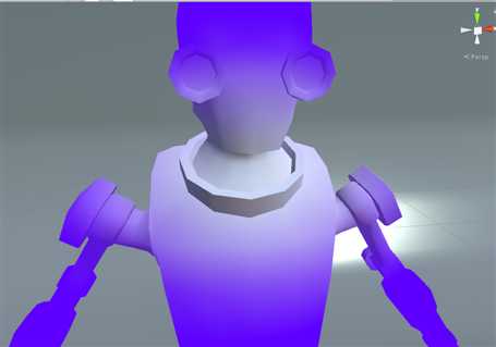
大概效果是这样的
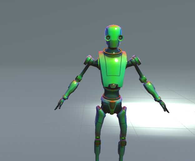
更多的实际用途可能是计算任何没有被内建输入变量提供的单个点上的某些数据,或者是优化shader的计算。比如说,你可以在游戏物体的定点计算边缘光,而不是在surfaceshader里逐顶点地做这件事。
也可以使用“final color modifier”函数可以修改shader计算出的最终的颜色。表面着色器编译指令 finalcolor:functionName就是用来做这个的,使用一个接受 Input IN,SurfaceOutput o,inout fixed4 color参数的函数。
这里有一个简单的示例,用来混合到最终的颜色中。这不同于我们修改表面的Albedo color之类的,这个颜色也会影响其他来自比如说光照贴图,光照组合和其他类似的额外资源。
Shader "Example/Tint Final Color" {
    Properties {
      _MainTex ("Texture", 2D) = "white" {}
      _ColorTint ("Tint", Color) = (1.0, 0.6, 0.6, 1.0)
    }
    SubShader {
      Tags { "RenderType" = "Opaque" }
      CGPROGRAM
      #pragma surface surf Lambert finalcolor:mycolor
      struct Input {
          float2 uv_MainTex;
      };
      fixed4 _ColorTint;
      void mycolor (Input IN, SurfaceOutput o, inout fixed4 color)
      {
          color *= _ColorTint;
      }
      sampler2D _MainTex;
      void surf (Input IN, inout SurfaceOutput o) {
           o.Albedo = tex2D (_MainTex, IN.uv_MainTex).rgb;
      }
      ENDCG
    }
    Fallback "Diffuse"
  }
下面来写一个雾效
通常来说使用final color modifier是用来实现完全自定义的雾效果的在前向渲染中。雾效果需要影响最终的计算出的点shader颜色,这正式final color所擅长的。
下面是一个shader基于距离屏幕中心的距离,这个结合了有着自定义定点数据的定点着色器与最终颜色编辑器。当forward rendering additive pass使用时,雾图像需要渐变为黑色。这个例子做到了并且展示了一个检测UNITY_PASS_FORWARDADD
Shader "Example/Fog via Final Color" {
    Properties {
      _MainTex ("Texture", 2D) = "white" {}
      _FogColor ("Fog Color", Color) = (0.3, 0.4, 0.7, 1.0)
    }
    SubShader {
      Tags { "RenderType" = "Opaque" }
      CGPROGRAM
      #pragma surface surf Lambert finalcolor:mycolor vertex:myvert
      struct Input {
          float2 uv_MainTex;
          half fog;
      };
      void myvert (inout appdata_full v, out Input data)
      {
          UNITY_INITIALIZE_OUTPUT(Input,data);
          float4 hpos = UnityObjectToClipPos(v.vertex);
          hpos.xy/=hpos.w;
          data.fog = min (1, dot (hpos.xy, hpos.xy)*0.5);
      }
      fixed4 _FogColor;
      void mycolor (Input IN, SurfaceOutput o, inout fixed4 color)
      {
          fixed3 fogColor = _FogColor.rgb;
          #ifdef UNITY_PASS_FORWARDADD
          fogColor = 0;
          #endif
          color.rgb = lerp (color.rgb, fogColor, IN.fog);
      }
      sampler2D _MainTex;
      void surf (Input IN, inout SurfaceOutput o) {
           o.Albedo = tex2D (_MainTex, IN.uv_MainTex).rgb;
      }
      ENDCG
    }
    Fallback "Diffuse"
  }
这个代码也比较好理解,就是先用顶点着色器计算出一个值fog。这个值是由顶点坐标XY的点积得到的。当然为了防止其大于1,用了一个min函数
然后就是到了mycolor 也就是finalcolor modifier里,我们用这个fog来对最终的颜色在原来颜色和雾的颜色之间插值,这样就得到了最后的雾图形。
由于是在剪裁空间中进行的计算,因此这个会随着摄像机的位置的变化而变化。(因为是雾图形嘛,不然也就不叫雾效了)
然后再来试一个线性的雾效吧
Shader "Example/Linear Fog" {
  Properties {
    _MainTex ("Base (RGB)", 2D) = "white" {}
  }
  SubShader {
    Tags { "RenderType"="Opaque" }
    LOD 200

    CGPROGRAM
    #pragma surface surf Lambert finalcolor:mycolor vertex:myvert
    #pragma multi_compile_fog

    sampler2D _MainTex;
    uniform half4 unity_FogStart;
    uniform half4 unity_FogEnd;

    struct Input {
      float2 uv_MainTex;
      half fog;
    };

    void myvert (inout appdata_full v, out Input data) {
      UNITY_INITIALIZE_OUTPUT(Input,data);
      float pos = length(UnityObjectToViewPos(v.vertex).xyz);
      float diff = unity_FogEnd.x - unity_FogStart.x;
      float invDiff = 1.0f / diff;
      data.fog = clamp ((unity_FogEnd.x - pos) * invDiff, 0.0, 1.0);
    }
    void mycolor (Input IN, SurfaceOutput o, inout fixed4 color) {
      #ifdef UNITY_PASS_FORWARDADD
        UNITY_APPLY_FOG_COLOR(IN.fog, color, float4(0,0,0,0));
      #else
        UNITY_APPLY_FOG_COLOR(IN.fog, color, unity_FogColor);
      #endif
    }

    void surf (Input IN, inout SurfaceOutput o) {
      half4 c = tex2D (_MainTex, IN.uv_MainTex);
      o.Albedo = c.rgb;
      o.Alpha = c.a;
    }
    ENDCG
  }
  FallBack "Diffuse"
}
(这个没试出来效果,也不懂这个原理是什么。。。。。。。。。。。)
贴花效果通常是用来给材质在运行时添加细节(比如说弹痕)在后处理渲染中他们特别有用,因为他们在被光照之前取代了Gbuffer,因此优化了性能。
在一个典型场景中,贴画效果应该是在非透明物体之后渲染并且应该不能造成阴影,就像在下面这个例子里,shaderlab的Tags里标记的一样。
Shader "Example/Decal" {
  Properties {
    _MainTex ("Base (RGB)", 2D) = "white" {}
  }
  SubShader {
    Tags { "RenderType"="Opaque" "Queue"="Geometry+1" "ForceNoShadowCasting"="True" }
    LOD 200
    Offset -1, -1

    CGPROGRAM
    #pragma surface surf Lambert decal:blend

    sampler2D _MainTex;

    struct Input {
      float2 uv_MainTex;
    };

    void surf (Input IN, inout SurfaceOutput o) {
        half4 c = tex2D (_MainTex, IN.uv_MainTex);
        o.Albedo = c.rgb;
        o.Alpha = c.a;
      }
    ENDCG
    }
}
标签:cto 翻译 and tar init 自定义 odi shader 分类
原文地址:http://www.cnblogs.com/Ash-game/p/7528626.html