标签:改变 tco etl starty lse jpg 一个 end col
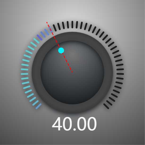
此次的 Demo 效果如下:
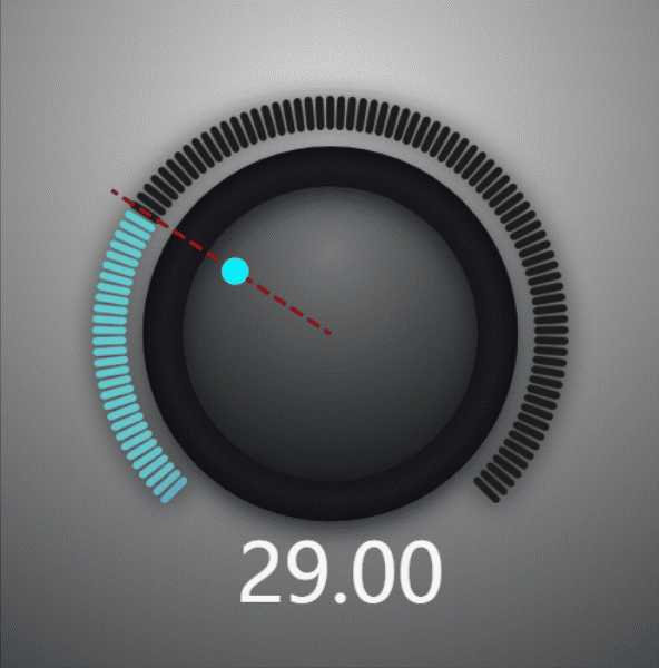
Demo 链接:https://hightopo.com/demo/comp-knob/
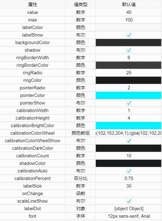
以下是下文会使用到的部分变量,在此先贴出来
var origin, // 原点
    percent, // 显示刻度占总刻度的百分比
    partAngle, // 每个刻度所占的角度
    startAngle, //刻度起始的角度
    calibrationPoints, // 每个刻度的信息
    pointer, // 指针的信息
    scaleLine, // 标尺的信息
    calibrationColors // 刻度渐变色
这里主要就使用了 canvas api 中的 arc() 和 createRadialGradient() 。
主要代码:
g.beginPath();
var ringRadial = g.createRadialGradient(origin.x, origin.y, 0, origin.x, origin.y, ringRadio);
ringRadial.addColorStop(0, ht.Default.brighter(ringColor, 20));
ringRadial.addColorStop(0.95, ht.Default.brighter(ringColor, 40));
ringRadial.addColorStop(1, ht.Default.darker(ringColor, 20));

var borderRadial = g.createRadialGradient(origin.x, origin.y, ringRadio - ringBorderWidth / 2, origin.x, origin.y, ringRadio + ringBorderWidth / 2);
borderRadial.addColorStop(0, ht.Default.brighter(ringBorderColor, 2));
borderRadial.addColorStop(0.5, ht.Default.brighter(ringBorderColor, 4));
borderRadial.addColorStop(1, ht.Default.darker(ringBorderColor, 4));
g.fillStyle = ringRadial;
g.lineWidth = ringBorderWidth;
g.strokeStyle = borderRadial;
g.arc(origin.x, origin.y, ringRadio, 0, 2 * Math.PI);
g.closePath();
g.fill();
g.stroke();
效果图:
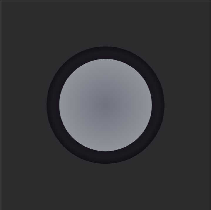
这里绘制每个刻度采用的是绘制路径的方法,所以声明了一个变量 calibrationPoints 用来存放每个刻度的起始点坐标,根据配置的参数去计算 calibrationPoints 的信息。
主要代码:
var calibrationPoints = [];
for (var i = 0; i < calibrationCount + 1; i++) {
    var point = {
        startx: origin.x + (ringRadio + ringBorderWidth + 0 * calibrationHeight) * Math.cos(startAngle - i * partAngle),
        starty: origin.y - (ringRadio + ringBorderWidth + 0 * calibrationHeight) * Math.sin(startAngle - i * partAngle),
        endx: origin.x + (ringRadio + ringBorderWidth + 1 * calibrationHeight) * Math.cos(startAngle - i * partAngle),
        endy: origin.y - (ringRadio + ringBorderWidth + 1 * calibrationHeight) * Math.sin(startAngle - i * partAngle)
    };
    if (i <= (calibrationCount * percent) && percent > 0) {
        point.show = true;
    } else {
        point.show = false;
    }
    calibrationPoints.push(point);
}
有了每个刻度的信息后,接下来就开始绘制刻度。首先绘制了所有的刻度,然后替换画笔颜色为高亮色,再绘制当前需要高亮的刻度。
主要代码:
calibrationPoints.forEach(function (i, index) {
    g.beginPath();
    if (calibrationColorWheelShow) {
        calibrationBrightColor = calibrationColors[index];
    }
    g.lineWidth = 1.2 * calibrationWidth;
    g.strokeStyle = i.show ? calibrationBrightColor : ht.Default.brighter(calibrationDarkColor, 10);

    g.moveTo(i.startx, i.starty);
    g.lineTo(i.endx, i.endy);
    g.closePath();
    g.stroke();
})

calibrationPoints.forEach(function (i, index) {
    g.beginPath();
    if (calibrationColorWheelShow) {
        calibrationBrightColor = calibrationColors[index];
    }
    g.lineWidth = calibrationWidth;
    g.strokeStyle = i.show ? calibrationBrightColor : calibrationDarkColor;

    g.moveTo(i.startx, i.starty);
    g.lineTo(i.endx, i.endy);
    g.closePath();
    g.stroke();
})
效果图:
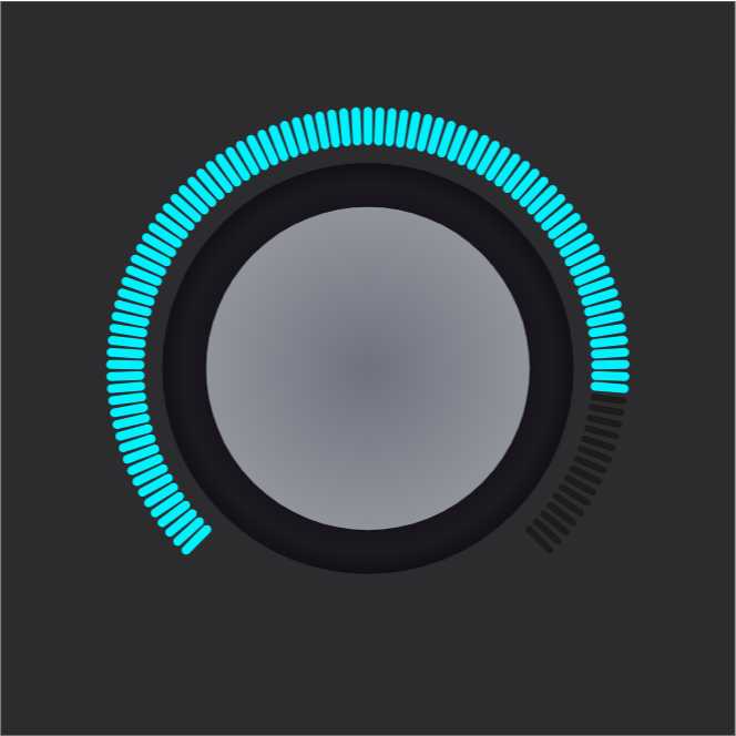
考虑到一种高亮颜色太单调,于是加了个色轮。思路:给每个刻度都添加了颜色的标识。
主要代码:
if (calibrationColorWheelShow) { // 显示刻度色轮
    var colors = [];
    calibrationColorWheel.forEach(function (i) {
        colors.push(ht.Default.toColorData(i))
    })
    // 把颜色值转换成rgb方式,设定多少秒改变完成,每次改变多少值,计算需要多少次
    // ,比如rba(x,y,z)到rgb(a,b,c),假设需要100次,那么每次设定
    // rgb((a-x)/100+x,(b-y)/100+y,(c-z)/100+z)
    var count = Math.ceil(calibrationCount / (calibrationColorWheel.length - 1)); // 渐变次数
    calibrationColors = [];
    for (var i = 0; i < colors.length - 1; i++) {
        for (var j = 1; j <= count; j++) {
            var item = ‘rgb(‘
                + Math.round((colors[i + 1][0] - colors[i][0]) / j + colors[i][0])
                + ‘,‘
                + Math.round((colors[i + 1][1] - colors[i][1]) / j + colors[i][1])
                + ‘,‘
                + Math.round((colors[i + 1][2] - colors[i][2]) / j + colors[i][2])
                + ‘)‘;
            calibrationColors.push(item)
        }
    }
}
效果图:
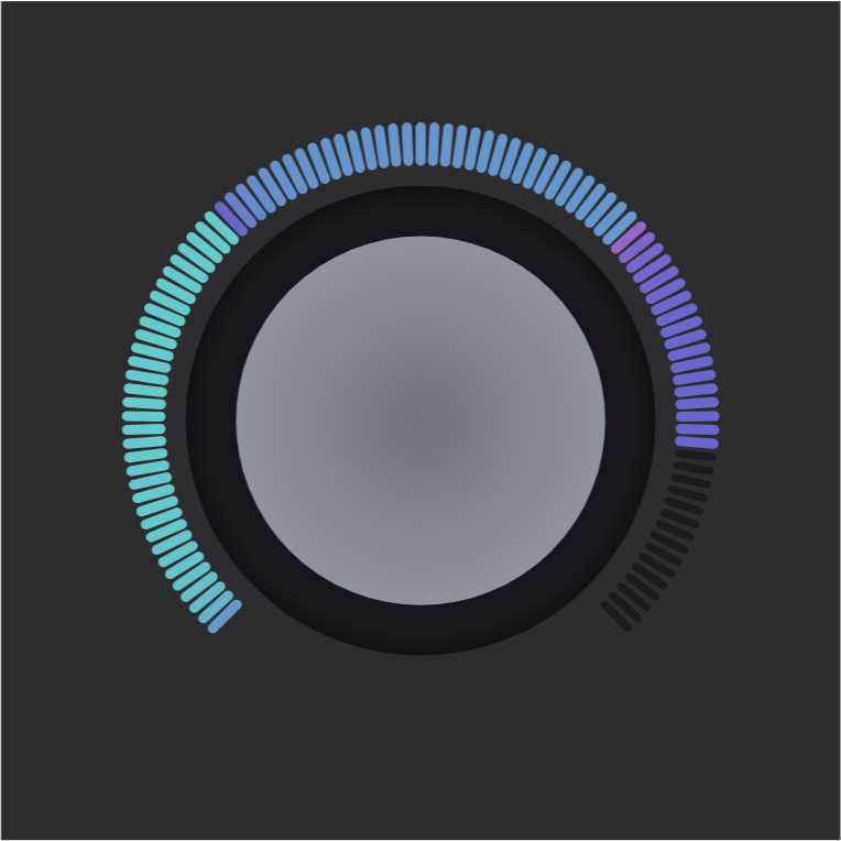
这个主要是根据三角函数去计算相对圆心的偏移角度,按照当前值和刻度最大值的比例来计算偏移量,然后换算成对应的坐标。
主要代码:
pointer = {
    x: origin.x + (ringRadio - pointerRadio - ringBorderWidth) * Math.cos(startAngle - Math.PI * 2 * calibrationPercent * percent),
    y: origin.y - (ringRadio - pointerRadio - ringBorderWidth) * Math.sin(startAngle - Math.PI * 2 * calibrationPercent * percent),
    r: pointerRadio,
    color: percent > 0 ? calibrationBrightColor : calibrationDarkColor,
    show: true,
}

if (pointerShow) {
    g.beginPath();
    g.fillStyle = pointer.color;
    g.arc(pointer.x, pointer.y, pointer.r, 0, Math.PI * 2);
    g.closePath();
    g.fill();
}
效果图:
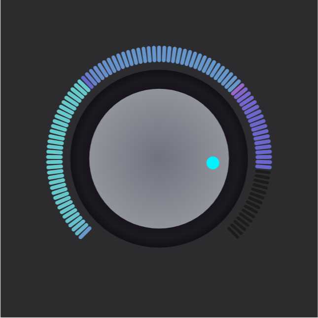
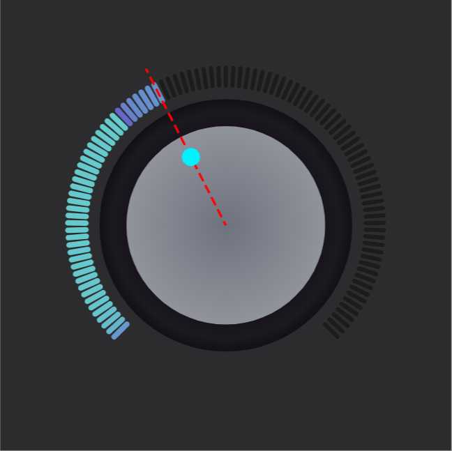
计算标尺角度的算法同指针。
主要代码:
scaleLine = {
    startx: origin.x,
    starty: origin.y,
    endx: origin.x + (ringRadio + ringBorderWidth + 2 * calibrationHeight) * Math.cos(startAngle - Math.PI * 2 * calibrationPercent * percent),
    endy: origin.y - (ringRadio + ringBorderWidth + 2 * calibrationHeight) * Math.sin(startAngle - Math.PI * 2 * calibrationPercent * percent),
    color: percent > 0 ? calibrationBrightColor : calibrationDarkColor,
    show: scaleLineShow,
}
if (scaleLine) {
    g.beginPath();
    g.strokeStyle = ‘red‘;
    g.setLineDash([1, 2]);
    g.lineWidth = 0.5 * calibrationWidth;
    g.moveTo(scaleLine.startx, scaleLine.starty);
    g.lineTo(scaleLine.endx, scaleLine.endy);
    g.closePath();
    g.stroke();
}
效果图:
主要代码:
if (labelShow) {
    var text = ht.Default.getTextSize(font, value);
    g.fillStyle = labelColor;
    g.font = font;
    g.fillText(value.toFixed(2), labelDot.x, labelDot.y);
}
效果图:
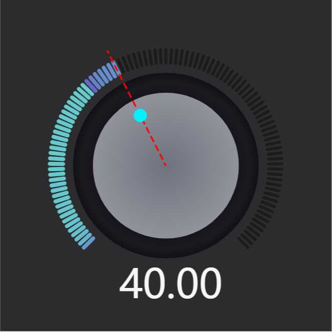
到这就完成了基本的旋钮组件,下面继续做一些细节上的优化。
主要代码:
var backgroundRadial = g.createRadialGradient(x + 0.5 * width, y + 0.2 * height, 0, x + 0.5 * width, y + 0.2 * height, Math.sqrt(Math.pow(width / 2, 2) + Math.pow(height, 2)));
backgroundRadial.addColorStop(0, ‘rgba(220,220,220,1)‘);
backgroundRadial.addColorStop(1, backgroundColor);
g.fillStyle = backgroundRadial;
g.fillRect(x, y, width, height);

g.beginPath();
var ringRadial = g.createRadialGradient(origin.x, origin.y - ringRadio / 2, 0, origin.x, origin.y - ringRadio / 2, 1.5 * ringRadio);
ringRadial.addColorStop(0, ht.Default.brighter(ringColor, 40));
// ringRadial.addColorStop(0.25, ht.Default.brighter(ringColor, 40));
ringRadial.addColorStop(1, ht.Default.darker(ringColor, 20));

var borderRadial = g.createRadialGradient(origin.x, origin.y, ringRadio - ringBorderWidth / 2, origin.x, origin.y, ringRadio + ringBorderWidth / 2);
borderRadial.addColorStop(0, ht.Default.brighter(ringBorderColor, 2));
borderRadial.addColorStop(0.5, ht.Default.brighter(ringBorderColor, 4));
borderRadial.addColorStop(1, ht.Default.darker(ringBorderColor, 4));
g.fillStyle = ringRadial;

g.lineWidth = ringBorderWidth;
g.strokeStyle = borderRadial;
g.arc(origin.x, origin.y, ringRadio, 0, 2 * Math.PI);
g.closePath();
g.fill();
g.shadowBlur = 20;
g.shadowColor = shadowColor;
g.shadowOffsetY = ringBorderWidth;
g.stroke();
g.shadowBlur = 0;
g.shadowOffsetY = 0;
效果图:
标签:改变 tco etl starty lse jpg 一个 end col
原文地址:https://www.cnblogs.com/htdaydayup/p/11258689.html