标签:html com 基本 zab 位图 direct code ash nio
原文:【WPF学习】第四十三章 路径和几何图形
前面四章介绍了继承自Shape的类,包括Rectangle、Ellipse、Polygon以及Polyline。但还有一个继承自Shape的类尚未介绍,而且该类是到现在为止功能最强大的形状类,即Path类。Path类能够包含任何简单形状、多组形状以及更复杂的要素,如曲线。
Path类提供了Data属性,该属性接受一个Geometry对象,该对象定义路径包含的一个或多个图形。不能直接创建Geometry对象,因为Geometry是抽象类,而且需要使用下表中列出的7个派生类的一个进行创建。
表 几何图形类

现在,可能会好奇路径和几何图形之间到底有什么区别。几何图形定义形状,而路径用于绘制形状。因此,Geometry对象为形状定义了坐标和尺寸等细节,而Path对象提供了用于绘制形状的Stroke和Fill画刷。Path类还提供了继承自UIElement基础架构的特性,如果鼠标和键盘处理。
然而,几何图形并不像看起来那么简单。原因之一是他们都继承自Freezable类(通过Geometry基类),所以支持更改通知。因此,如果使用集合图形创建路径,然后修改几何图形,就会自动被重新绘制路径。还可以使用几何图形类来定义能够通过画刷应用的图画,从而为绘制不需要Path类所具有的用户交互功能的复杂内容提供一种简单方法。
一、直线、矩形和椭圆图形
LineGeometry、RectangleGeometry以及EllipseGeometry类直接对应于Line、Rectangle以及Ellipse形状。例如,可将下面使用Rectangle元素的标记:
<Rectangle Fill="Yellow" Stroke="Blue" Width="100" Height="50"></Rectangle>
转换为下面使用Path元素的标记:
<Path Fill="Yellow" Stroke="Blue">
            <Path.Data>
                <RectangleGeometry Rect="0 0 100,50"></RectangleGeometry>
            </Path.Data>
</Path>
唯一的实质性区别是Rectangle形状使用的是Height和Width值,而RectangleGeometry图形使用4个数值来描述矩形的尺寸和位置。前两个数值描述左上角的X和Y坐标,而后两个数值设置为矩形的宽度和高度。可在(0,0)点开始绘制矩形,从而得到与普通的Rectangle元素相同的效果,或者使用不同的值偏移矩形。RectangleGeometry类还提供了RadiuX和RadiuY属性,这两个属性用于圆滑拐角。
类似地,可将下面的Line形状:
<Line Stroke="Blue" X1="0" Y1="0" X2="50" Y2="10"></Line>
转变成下面的LineGeometry图形:
<Path Stroke="Blue" Fill="Yellow">
            <Path.Data>
                <LineGeometry StartPoint="0,0" EndPoint="50,10"></LineGeometry>
            </Path.Data>
        </Path>
也可将如下的Ellipse形状:
<Ellipse Fill="Yellow" Stroke="Blue" Width="100" Height="50" HorizontalAlignment="Left"></Ellipse>
转变成下面的EllipseGeometry图形:
<Path Fill="Yellow" Stroke="Blue">
            <Path.Data>
                <EllipseGeometry RadiusX="50" RadiusY="25" Center="50,25"></EllipseGeometry>
            </Path.Data>
</Path>
注意,两个半径值只是宽度和高度值得一半。还可使用Center属性偏移椭圆的位置。在该例中,中心被设置为椭圆外包围框的正中心位置,所以使用与绘制Ellipse形状完全相同的方式来绘制椭圆图形。
总之,这些简单图形和对应的形状使用相同的工作方式。虽然具有额外的可偏移矩形和椭圆的功能,但如果在Canvas面板上放置形状,该功能是没有必要的,因为已经具有将形状定位到特定位置的能力。实际上,如果这就是图形所能完成的所有内容,可能觉得使用Path元素很烦人。
二、使用GeometryGroup组合形状
组合图形最简单的方法是使用GeometryGroup对象,该对象在内部嵌套其他Geometry类的派生类对象。下面的示例在一个正方形的旁边放置了一个椭圆:
<Path Fill="Yellow" Stroke="Blue" Margin="5" Canvas.Top="10" Canvas.Left="10" >
            <Path.Data>
                <GeometryGroup>
                    <RectangleGeometry Rect="0 0 100 100"></RectangleGeometry>
                    <EllipseGeometry Center="50 50" RadiusX="35" RadiusY="25"></EllipseGeometry>
                </GeometryGroup>
            </Path.Data>
</Path>
效果图如下所示:
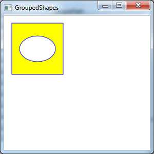
上面标记的效果和如下两个Path元素的效果相同,其中一个Path元素具有RectangleGeometry,而另一个Path元素具有EllipseGeometry(而且像是改用Rectangle和Ellipse形状)。然而,这两种方法有一个优点。用一个元素替代了两个元素,这意味着降低了用户界面的开销。通常,使用数量更少的较复杂集合图形元素的窗口比具有大量较简单集合图形元素的窗口的性能要高。在只有几十个形状的窗口中这一效果并不明显,但对于需要几百或几千个形状的窗口,这一问题就会变得更重要了。
当然,将多个几何图形组合成单独的Path元素也存在缺点——不能单独为不同的形状执行事件处理。反而,Path元素将引发所有的鼠标事件。不过,仍可以独立地控制嵌套的RectangleGeometry和EllipseGeometry对象,从而改变整个路径。例如,每个几何图形都提供了Transform属性,可使用该属性拉伸、扭曲和选择路径的响应部分。
几何图形的另一个优点是可在几个独立的Path元素中重用相同的几何图形。这不需要使用代码——只需要在Resources结合中定义集合图形,并使用StaticExtension或DynamicExtension标记扩展在路径中进行引用。下面的例子对前面显示的例子进行了重写,在Canvas容器的两个不同位置使用两种相同颜色来显示CombinedGeometry实例:

<Window x:Class="Drawing.CombiningShapes"
        xmlns="http://schemas.microsoft.com/winfx/2006/xaml/presentation"
        xmlns:x="http://schemas.microsoft.com/winfx/2006/xaml"
        Title="CombiningShapes" Height="300" Width="300">
    <Window.Resources>
        <GeometryGroup x:Key="Geometry">
            <RectangleGeometry Rect="0,0 100,100"></RectangleGeometry>
            <EllipseGeometry Center="150,50" RadiusX="35" RadiusY="25"></EllipseGeometry>
        </GeometryGroup>
    </Window.Resources>
    <Canvas>
        <Path Fill="Yellow" Stroke="Blue" Margin="5" Canvas.Top="10" Canvas.Left="10"
              Data="{StaticResource Geometry}">
        </Path>
        <Path Fill="Yellow" Stroke="Blue" Margin="5" Canvas.Top="150" Canvas.Left="10"
              Data="{StaticResource Geometry}">
        </Path>
    </Canvas>
</Window>
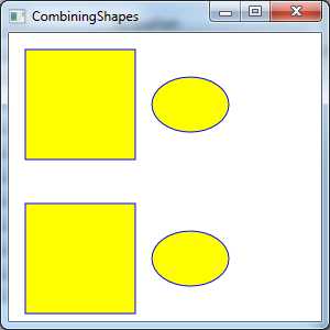
当形状相互交叉时,GeometryGroup将更有趣。这时不能将图画简单地作为固定形状的组合对待,GeometryGroup使用FillRule属性(该属性可设置为EventOdd或Nonzero)决定填充哪些形状。如果采用如下方式改变前面显示的标记,在正方形的上面放置椭圆,分析一下会出现什么情况:
<Path Fill="Yellow" Stroke="Blue" Margin="5" Canvas.Top="10" Canvas.Left="10" >
            <Path.Data>
                <GeometryGroup>
                    <RectangleGeometry Rect="0 0 100 100"></RectangleGeometry>
                    <EllipseGeometry Center="50 50" RadiusX="35" RadiusY="25"></EllipseGeometry>
                </GeometryGroup>
            </Path.Data>
        </Path>
现在,上面的标记创建了一个正方形,这个正方形的内部有一个椭圆形状的空洞。如果将FillRule属性修改为Nonezero,在纯色正方形的上面就会有一个纯色的椭圆,椭圆和正方形都使用黄色填充。
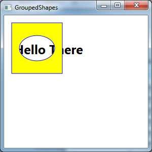
通过在正方形的上面重叠以白色填充的椭圆,可创建有洞得正方形。然而,如果在下面有内容,GeometryGroup类会变得更有用处。因为在你的形状中椭圆被视为洞,后面的内容都可透过该洞显示。如下示例所示:

 <Canvas>
        <TextBlock Canvas.Top="50" Canvas.Left="20" FontSize="25" FontWeight="Bold">Hello There</TextBlock>

        <Path Fill="Yellow" Stroke="Blue" Margin="5" Canvas.Top="10" Canvas.Left="10" >
            <Path.Data>
                <GeometryGroup>
                    <RectangleGeometry Rect="0 0 100 100"></RectangleGeometry>
                    <EllipseGeometry Center="50 50" RadiusX="35" RadiusY="25"></EllipseGeometry>
                </GeometryGroup>
            </Path.Data>
        </Path>

    </Canvas>
三、使用CombinedGeometry融合几何图形
对于通过基本图元(矩形、椭圆和直线)构建复杂形状,GeometryGroup类是非常有价值的工具。但它也有明显的局限性。如果是绘制形状,并在其内部“减去”另一个形状来创建新的形状,GeometryGroup类可以工作的很好。然而,如果形状的边界相互交叉,就很难得到所希望的结果了,并且如果希望移除形状的一部分,GeometryGroup类就不能提供任何帮助了。
CombinedGeometry类专门用于组合重叠到一起并且不相互包含的形状。与GeometryGroup类不同,CombinedGeometry类只使用两个几何图形,通过Geometry1和Geometry2属性提供这两个几何图形。CombinedGeometry类没有包含FillRule属性,反而具有功能更强大的GeometryCombineMode属性,该属性可以使用4个值中的一个,下表列出了这4个值。
表 GeometryCombineMode枚举值

例如,下面的示例演示了GeometryCombineMode:

<Window x:Class="Drawing.CombineGeometryShapes"
        xmlns="http://schemas.microsoft.com/winfx/2006/xaml/presentation"
        xmlns:x="http://schemas.microsoft.com/winfx/2006/xaml"
        Title="CombineGeometryShapes" Height="481" Width="341">
    <Window.Resources>
        <RectangleGeometry x:Key="rect" Rect="0 0 100 100"></RectangleGeometry>
        <EllipseGeometry x:Key="ellipse" Center="85 50" RadiusX="65" RadiusY="35"></EllipseGeometry>
    </Window.Resources>
    <Grid Margin="5" TextBlock.FontSize="16">
        <Grid.RowDefinitions>
            <RowDefinition Height="Auto"></RowDefinition>
            <RowDefinition Height="Auto"></RowDefinition>
            <RowDefinition Height="Auto"></RowDefinition>
            <RowDefinition Height="Auto"></RowDefinition>
        </Grid.RowDefinitions>
        <Grid.ColumnDefinitions>
            <ColumnDefinition Width="Auto"></ColumnDefinition>
            <ColumnDefinition Width="Auto"></ColumnDefinition>
        </Grid.ColumnDefinitions>

        <Path Fill="Yellow" Stroke="Blue" Margin="5">
            <Path.Data>
                <CombinedGeometry GeometryCombineMode="Union"
            CombinedGeometry.Geometry1="{StaticResource rect}"
            CombinedGeometry.Geometry2="{StaticResource ellipse}">
                </CombinedGeometry>
            </Path.Data>
        </Path>
        <TextBlock Grid.Column="1" Margin="10" VerticalAlignment="Center">Union</TextBlock>

        <Path Grid.Row="1" Fill="Yellow" Stroke="Blue" Margin="5">
            <Path.Data>
                <CombinedGeometry GeometryCombineMode="Intersect"
            CombinedGeometry.Geometry1="{StaticResource rect}"
            CombinedGeometry.Geometry2="{StaticResource ellipse}">
                </CombinedGeometry>
            </Path.Data>
        </Path>
        <TextBlock Grid.Row="1" Grid.Column="1" Margin="10" VerticalAlignment="Center">Intersect</TextBlock>

        <Path Grid.Row="2" Fill="Yellow" Stroke="Blue" Margin="5">
            <Path.Data>
                <CombinedGeometry GeometryCombineMode="Xor"
            CombinedGeometry.Geometry1="{StaticResource rect}"
            CombinedGeometry.Geometry2="{StaticResource ellipse}">
                </CombinedGeometry>
            </Path.Data>
        </Path>
        <TextBlock Grid.Row="2" Grid.Column="1" Margin="10" VerticalAlignment="Center">Xor</TextBlock>

        <Path Grid.Row="3" Fill="Yellow" Stroke="Blue" Margin="5">
            <Path.Data>
                <CombinedGeometry GeometryCombineMode="Exclude"
            CombinedGeometry.Geometry1="{StaticResource rect}"
            CombinedGeometry.Geometry2="{StaticResource ellipse}">
                </CombinedGeometry>
            </Path.Data>
        </Path>
        <TextBlock Grid.Row="3" Grid.Column="1" Margin="10" VerticalAlignment="Center">Exclude</TextBlock>

    </Grid>
</Window>
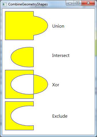
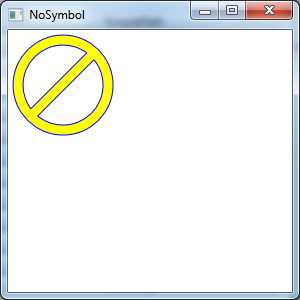
为理解这种组合的工作原理,下图中显示的简单的“no"符合(一个有斜杠贯穿其中的圆)。尽管任何一个WPF基本元都与该形状不同,但可以用CombinedGeometry对象很快装配出该符号。

<Window x:Class="Drawing.NoSymbol"
        xmlns="http://schemas.microsoft.com/winfx/2006/xaml/presentation"
        xmlns:x="http://schemas.microsoft.com/winfx/2006/xaml"
        Title="NoSymbol" Height="300" Width="300">
    <StackPanel Margin="5">

        <Path Fill="Yellow" Stroke="Blue">
            <Path.Data>
                <CombinedGeometry GeometryCombineMode="Union">
                    <CombinedGeometry.Geometry1>
                        <CombinedGeometry GeometryCombineMode="Exclude">
                            <CombinedGeometry.Geometry1>
                                <EllipseGeometry Center="50 50" RadiusX="50" RadiusY="50"></EllipseGeometry>
                            </CombinedGeometry.Geometry1>
                            <CombinedGeometry.Geometry2>
                                <EllipseGeometry Center="50 50" RadiusX="40" RadiusY="40"></EllipseGeometry>
                            </CombinedGeometry.Geometry2>
                        </CombinedGeometry>
                    </CombinedGeometry.Geometry1>
                    <CombinedGeometry.Geometry2>
                        <RectangleGeometry Rect="44 5 10 90">
                            <RectangleGeometry.Transform>
                                <RotateTransform Angle="45" CenterX="50" CenterY="50"></RotateTransform>
                            </RectangleGeometry.Transform>
                        </RectangleGeometry>
                    </CombinedGeometry.Geometry2>
                </CombinedGeometry>
            </Path.Data>
        </Path>


    </StackPanel>
</Window>
四、使用PathGeometry绘制曲线和直线
PathGeometry是功能超级强大的图形,它能绘制其他所有几何图形能够绘制的内容,也能绘制其他所有几何图形所不能绘制的内容。它的唯一缺点是语法比较长(并且在某种程度上更加复杂)。
每个PathGeometry对象都是由一个或多个PathFigure对象构建的(存储在PathGeometry.Figures集合中)。每个PathFigure对象是一系列相互连接的直线和曲线,可闭合也可不闭合。如果图形中最后一条直线的终点连接到了第一条直线的起点,那么图形就是闭合的。
PathFigure类包含4个重要属性,如下表所示。
表 PathFigure属性

PathFigure对象是由包含大量线段的不间断线条绘制的形状。然而,技巧是有几种类型的线段,它们都继承自PathSegment类。其中一些类比较简单,如绘制直线的LineSegment类。而另外一些类(如BezierSegment类)较为复杂,可以绘制曲线。
可自由地混合并匹配不同的线段来构建图形,下表列出了可供使用的线段类。
表 PathSegment类
| 名 称 | 说 明 |
| LineSegment | 在两点之间创建直线 |
| ArcSegment | 在两点之间创建椭圆形弧线 |
| BezierSegment | 在两点之间创建贝塞尔曲线 |
| QuadraticBezierSegment | 创建形式更简单的贝塞尔曲线,只有一个控制点而不是两个控制点,并且计算速度更快 |
| PolyLineSegment | 创建一系列直线。可使用多个LineSegment对象得到相同的效果,但使用单个PolyLineSegment对象更简明 |
| PolyBezierSegment | 创建一系列贝塞尔曲线 |
| PolyQuadraticBezierSegment | 创建一系列更简单的二次贝塞尔曲线 |
1、直线
使用LineSegment和PathGeometry类创建简单的线条非常容易。只需要设置StartPoint属性,并为线条中的每部分增加一条LineSegment直线段。LineSegment.Point属性标识每条线段的结束点。
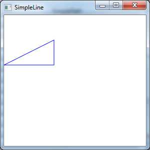
例如,下面的标记是从点(10,100)开始,绘制一条到点(100,100)的直线,然后从点(100,100)开始绘制到点(100,50)的直线。因为PathFigure.IsClosed属性设置为true,所以添加的最后一条线段将点(100,50)连接到点(0,0)。最后的结果是直角三角形。
<Path Stroke="Blue">
            <Path.Data>
                <PathGeometry>
                    <PathFigure IsClosed="True" StartPoint="0,100">
                        <LineSegment Point="100,100"/>
                        <LineSegment Point="100,50"/>
                    </PathFigure>
                </PathGeometry>
            </Path.Data>
        </Path>
效果图如下所示:
2、弧线
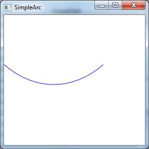
弧线比直线更有趣。就像使用LineSegment类时一样,使用ArcSegment.Point属性指定弧线段终点。不过,PathFigure从起点(或前一条线段的终点)向弧线的终点绘制一条曲线。这条弯曲的连接线实际是椭圆边缘的一部分。
显然,为了绘制弧线,只有终点是不够的,因为有许多曲线(一些弯曲程度较缓和,另一些弯曲的程度更大)能够连接这两点。还需要指定用于绘制弧线的假想椭圆的尺寸。可使用ArgSegment.Size属性完成工作,该属性提供了椭圆的X半径和Y半径。假想的椭圆越大,边缘曲线就越缓和。
下面的示例创建了弧线。
<Path Stroke="Blue">
            <Path.Data>
                <PathGeometry>
                    <PathFigure StartPoint="0,100" IsClosed="False">
                        <ArcSegment Point="200,100" Size="200,300"></ArcSegment>
                    </PathFigure>
                </PathGeometry>
            </Path.Data>
        </Path>
到目前为止,弧线听起来似乎很简单。然而,即使提供了起点、终点以及椭圆的尺寸,也仍不具备明确绘制弧线所需的全部信息。上面的示例还依赖与两个默认值,如果喜欢的话,也可以使用其他值。
为了理解该问题,需要分析能连接相同两点的弧线的其他方式。如果绘制椭圆上的两个点,显示可以由两种方式连接它们——通过沿着短边连接两点,或沿着长边连接两点。
可用ArgSegment.IsLargeArc属性何止弧线的方向,可将该属性设置为true或false。默认是false,这意味着使用两条弧线中较短的一条。
即使设置了方向,也还有一点需要明确——椭圆位于何处。设想绘制一条弧线连接左边的一点或右边的一点,并使用尽可能短的弧线。连接这两个点的曲线可被向下拉伸,然后向上拉上拉伸;也可以翻转该弧线,从而先向上弯曲,然后向下弯曲。得到的弧线依赖与定义弧线的两点的顺序以及ArgSegment.SweepDirection属性,该属性可以是Counterclockwise(默认值)或Clockwise。
3、贝塞尔曲线
贝塞尔曲线使用更复杂的数学公式连接两条线段,该公式包含的两个控制点决定了曲线的性质。实际上,贝塞尔曲线是每个矢量绘图程序都会创建的要素,因为他们非常灵活。只需要使用起点、终点和两个控制点。就可以创建出令人称奇的各种光滑曲线(包括回线(loop))。如下图所示,显示了一条经典的贝塞尔曲线,两个小圆指示了控制点而曲线将每个控制点连接到受控制点影响最大的线条端点。

<Window x:Class="Drawing.BezierCurve"
        xmlns="http://schemas.microsoft.com/winfx/2006/xaml/presentation"
        xmlns:x="http://schemas.microsoft.com/winfx/2006/xaml"
        Title="BezierCurve" Height="300" Width="300">
    <Canvas>
        <Path Stroke="Blue" StrokeThickness="5" Canvas.Top="20">
            <Path.Data>
                <PathGeometry>
                    <PathGeometry.Figures>
                        <PathFigure StartPoint="10,10">
                            <BezierSegment Point1="130,30" Point2="40,140" Point3="150,150"></BezierSegment>
                        </PathFigure>
                    </PathGeometry.Figures>
                </PathGeometry>
            </Path.Data>
        </Path>
        <Path Stroke="Green" StrokeThickness="2" StrokeDashArray="5 2" Canvas.Top="20">
            <Path.Data>
                <GeometryGroup>
                    <LineGeometry StartPoint="10,10" EndPoint="130,30"></LineGeometry>
                    <LineGeometry StartPoint="40,140" EndPoint="150,150"></LineGeometry>
                </GeometryGroup>
            </Path.Data>
        </Path>
        <Path Fill="Red" Stroke="Red" StrokeThickness="8"  Canvas.Top="20">
            <Path.Data>
                <GeometryGroup>
                    <EllipseGeometry Center="130,30"></EllipseGeometry>
                    <EllipseGeometry Center="40,140"></EllipseGeometry>
                </GeometryGroup>
            </Path.Data>
        </Path>
    </Canvas>
</Window>
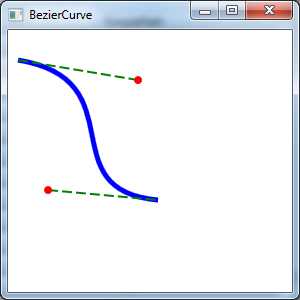
即使不理解贝塞尔曲线的数学原理,也很容易”感觉“出贝塞尔曲线的工作原理。本质上,两个控制点是所有问题的关键。他们以两种方式影响曲线:
为在标记中定义贝塞尔曲线,需要提供三个点。前两个点(BezierSegment.Point1和BezierSegment.Point2)是控制点,第三个点(BezierSegment.Point3)是曲线的终点。同样,起点是路径的起点或前一条线段的终点。
五、微语言几何图形
到目前为止看到的几何图形都比较简明,只用了少数几个点。更复杂的集合图形在该概念上与此相同,只不过动辄就需要几百条线段。在复杂路径中定义每条直线、弧线以及曲线非常繁琐而且不是必需的——毕竟,复杂曲线可能由设计工具生成,而不是通过手工编写,所以保持标记的清晰性并不是最重要的。为此,WPF创作人员为定义几何图形增加了一种更简明的替换语法,通过该语法可用更少的标记表示详细的图形。这种语法通常称为图形微语言(geometry mini-language),并且由于应用于Path元素,因此有时候称为路径微语言。
为理解微语言,需要认识到它在本质上包含一系列命令的长字符串。这些命令由类型转换器读取,然后创建响应的几何图形。每个命令都是单独的字母,后面可选地跟随一些由空格分隔的数字信息(如X和Y坐标)。每个命令也使用空格与前面的命令隔开。
例如,在前面使用具有两条线路的闭合路径创建了一个基本三角形,下面是绘制这个三角形的标记:
<Path Stroke="Blue">
            <Path.Data>
                <PathGeometry>
                    <PathFigure IsClosed="True" StartPoint="10,100">
                        <LineSegment Point="100,100" />
                        <LineSegment Point="100,50" />
                    </PathFigure>
                </PathGeometry>
            </Path.Data>
        </Path>
使用微语言创建该图形,英按如下方式编写标记:
<Path Stroke="Blue" Data="M 10,100 L 100,100 L 100,50 Z"/>
这个路径使用一个包含4个命令的命令序列。第一个命令(M)创建PathFigure,并将起点设置为(10,100)。接下来的两个命令(L)创建线段。最后一个命令(Z)结束PathFigure,并将IsClosed属性设置为True。这个字符串中的逗号是可选的,同样,命令及其参数之间的空格也是可选的,但在相邻的两个参数之间以及命令之间至少要保留一个空格。这意味着可以进一步精简语法,形成下面这种更难度的形式:
<Path Stroke="Blue" Data="M10 100 L100 100 L100 50 Z"/>
当使用微语言创建集合图形时,实际上是创建了StreamGeometry对象而不是PathGeometry对象。因此,以后在代码中不能修改图形。如果这是不能接受的,可显示地创建PathGeometry对象,但使用相同的语法定义其PathFigure对象集合。如下所示:
<Path Stroke="Blue">
            <Path.Data>
                <PathGeometry Figures="M 10,100
          L 100,100 L 100,50 Z"></PathGeometry>
            </Path.Data>
        </Path>
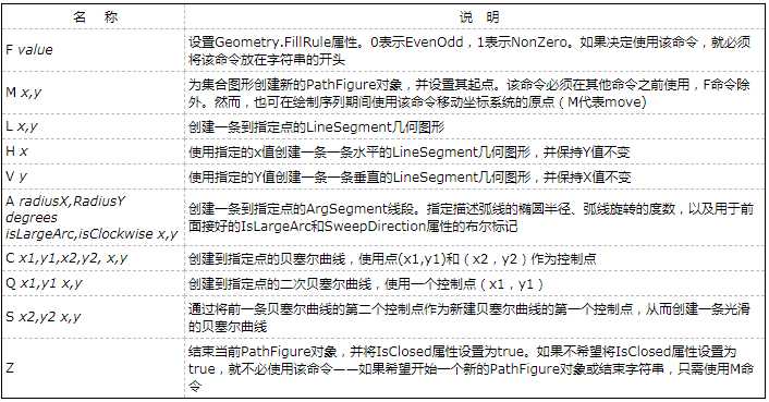
微语言几何图形很容易理解。它使用下表中详细描述的一小组命令。参数以斜体显示:
表 微语言图形命令
六、使用几何图形进行裁剪
几何图形是创建形状的最强大方法。然而,几何图形不仅可用于Path元素,也可为任何需要的地方提供抽象的图形定义(而不是在窗口中绘制真实的具体形状)。
几何图形的另一个用途是用于设置Clip属性,所有元素都提供了该属性。可以通过Clip属性约束元素的外边界以符合特定的几何图形。可使用Clip属性创建大量的特殊效果。尽管该属性通常用于修剪Image元素中的图像内容,但也可将Clip属性应用于任何元素。唯一的限制是,如果确实希望看到一些内容——而不仅是用处不大的单独曲线和线段,需要使用闭合的几何图形。
下面的示例定义了一个集合图形,该集合图形用于裁剪两个元素,一个是包含一副位图的Image元素,另一个是标准的Button元素。
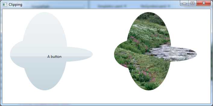
下面是该例的标记:

<Window.Resources>
        <GeometryGroup x:Key="clipGeometry" FillRule="Nonzero">
            <EllipseGeometry RadiusX="75" RadiusY="50" Center="100,150"></EllipseGeometry>
            <EllipseGeometry RadiusX="100" RadiusY="25" Center="200,150"></EllipseGeometry>
            <EllipseGeometry RadiusX="75" RadiusY="130" Center="140,140"></EllipseGeometry>
        </GeometryGroup>
    </Window.Resources>
    <Grid>
        <Grid.ColumnDefinitions>
            <ColumnDefinition></ColumnDefinition>
            <ColumnDefinition></ColumnDefinition>
        </Grid.ColumnDefinitions>

        <Button Clip="{StaticResource clipGeometry}">A button</Button>
        <Image Grid.Column="1" Clip="{StaticResource clipGeometry}"
           Stretch="None"  Source="creek.jpg"></Image>
    </Grid>
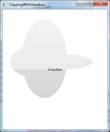
使用裁剪存在限制。设置的裁剪不会考虑元素的尺寸。换句话说,当改变窗口尺寸时,不管上图中显示的按钮变大还是变小,裁剪区域仍保留原样,并显示按钮的不同部分。一种可能的解决方案是在Viewbox控件中封装元素,以便提供自动重新缩放功能。但这会导致所有内容都按比例地改变尺寸,包括希望改变尺寸的一些细节(裁剪区域和按钮表面)以及那些可能不希望改变的内容。
如下示例使用Viewbox控件所示:

<Window.Resources>
        <GeometryGroup x:Key="clipGeometry" FillRule="Nonzero">
            <EllipseGeometry RadiusX="75" RadiusY="50" Center="100,150"></EllipseGeometry>
            <EllipseGeometry RadiusX="100" RadiusY="25" Center="200,150"></EllipseGeometry>
            <EllipseGeometry RadiusX="75" RadiusY="130" Center="140,140"></EllipseGeometry>
        </GeometryGroup>
    </Window.Resources>
    <Grid>
        <Viewbox >
            <Button Width="350" Height="350" Clip="{StaticResource clipGeometry}">A button</Button>
        </Viewbox>
    </Grid>
标签:html com 基本 zab 位图 direct code ash nio
原文地址:https://www.cnblogs.com/lonelyxmas/p/12318348.html