标签:sys erro man add util model device ase pos
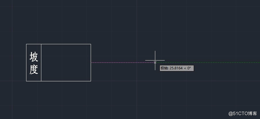
C++实现坡度编辑命令,指定基点的情况下提示用户拾取一个点。主要思路是:
图例如下:

示例如下:
程序入口点代码
```c++
//zhaoanan 坡度绘制
// - zndraw_thslope command (do not rename)
//自定义实体绘制坡度
static void zndraw_thslope(void)
{
AcDbDatabase m_pDb = acdbHostApplicationServices()->workingDatabase();
//添加块定义
acutPrintf(_T("\n坡度绘制")) ;
CUserSystem mysys = new CUserSystem();
mysys->m_pDb = m_pDb;
//声明左边插入点
ads_point pt_insert;
AcGePoint3d pt_3d_insert;
int iOldOsMode = 0 ;
BOOL bReturn = false ;
while (bReturn == false)
{
int iReturn = acedGetPoint(NULL,_T("\n 指定坡度的插入点:"),pt_insert) ;
//int iReturn = acedEntSel(_T("\n选择实体对象"), en, pt) ;
if(iReturn == RTNORM)
{
    bReturn = true ;

    pt_3d_insert =asPnt3d(pt_insert);

    acutPrintf(_T("\n坡度插入点坐标:x坐标为:%f,y坐标为:%f"), pt_3d_insert.x, pt_3d_insert.y);
    //实例化轨道坡度对象
    CthRailSlope *cthRailSlope = new CthRailSlope();
    //指定坡度位置为插入点坐标
    cthRailSlope->setPosition(pt_3d_insert);
    //添加坡度组件
    CthComponent *lineCp = new CthComponent();
    //thComponent c = new thComponent();
    //根据插入点,画坡度上面的横线
    lineCp->addLine(AcGePoint3d(-26, 7.5, 0), AcGePoint3d(0, 7.5, 0));
    //根据插入点,画坡度下面的横线
    lineCp->addLine(AcGePoint3d(-26, -7.5, 0), AcGePoint3d(0, -7.5, 0));
    //以插入点横坐标X=-26为基准向上和向下画竖线
    lineCp->addLine(AcGePoint3d(-26, 7.5, 0), AcGePoint3d(-26, -7.5, 0));
    //添加坡度框体中间的文字
    CthText *text = lineCp->addText(_T("坡"), AcGeVector3d(-23, 2.5, 0), 3);
    //指定字体对齐方式
    text->setAlign(AcDbMText::kMiddleCenter);
    text = lineCp->addText(_T("度"), AcGeVector3d(-23, -2.5, 0), 3);
    //指定字体对齐方式
    text->setAlign(AcDbMText::kMiddleCenter);
    //以插入点横坐标X=-20为基准向上和向下画竖线
    lineCp->addLine(AcGePoint3d(-20, 7.5, 0), AcGePoint3d(-20, -7.5, 0));
    //将新建的组件添加到坡度对象
    cthRailSlope->appendComponent(lineCp);
    lineCp = new CthComponent();
    //type=1, 没查到代表什么
    lineCp->setType(1);
    //根据插入点,以插入点为基准向上和向下画竖线
    lineCp->addLine(AcGePoint3d(pt_3d_insert.x, pt_3d_insert.y + 7.5, 0), AcGePoint3d(pt_3d_insert.x, pt_3d_insert.y - 7.5, 0));
    //给新加的竖线添加文字
    text = lineCp->addText(_T(""), AcGeVector3d(pt_3d_insert.x, pt_3d_insert.y, 0), 2.5);
    text->setName(_T("里程"));
    //指定字体旋转角度
    text->setRotation(PI / 2);
    //指定字体对齐方式
    text->setAlign(AcDbMText::kBottomCenter);
    //将新建的组件添加到坡度对象
    cthRailSlope->appendComponent(lineCp);
    //获取devices.xml中的图层信息,给新建坡度对象添加图层
    DTDevice* device = CZnUtility::GetDevice(cthRailSlope);
    //如果获取的devices.xml中的坡度相关图层信息不为空
    if(device != nullptr && (!device->GetLayer().IsEmpty()))
    {
        //将图层信息添加到图层表中
        if (addLayer(device))
        {
            //如果图层信息添加到图层表成功,那么将图层信息赋值给当前坡度图层
            cthRailSlope->setLayer(device->GetLayer());
        }
    }

    //将里程实体加入到块表记录中
    //cthRailSlope->AddRailSlope("ZDK1+222.45", "ZDK2+123.11", "20", 20.00, "30", cthRailSlope->position().x + 20, cthRailSlope->position().x + 50, 1);
    AcDbObjectId dimensionId = CDwgDatabaseUtil::PostToModelSpace(cthRailSlope, m_pDb);
}
else if (iReturn == RTERROR)
{
    bReturn = false ;
}
else if (iReturn == RTCAN) {
    bReturn = true ;
}
}
//保存当前图层,设置要绘制的图层
AcDbObjectId ojbIdLayerOld = m_pDb->clayer() ;
m_pDb->setClayer(ojbIdLayerOld) ; //恢复当前图层
}
拖拽程序代码,要有坡度编辑的时候有参照线,指定基点的情况下提示用户拾取一个点,代码实现:
```c++
//刷新窗口 当即生效
int CGetInputUtil::GetPointReturnCode(const AcGePoint3d &basePoint, const TCHAR* prompt, AcGePoint3d &point)
{
//将基点转换为UCS坐标
AcGePoint3d ucsBasePoint = CConvertUtil::WcsToUcsPoint(basePoint);
int nReturn = acedGetPoint(asDblArray(ucsBasePoint), prompt, asDblArray(point));
if (nReturn == RTNORM)
{
//acedGetPoint得到UCS坐标,转换为WCS
point = CConvertUtil::UcsToWcsPoint(point);
}
return nReturn;
}
坡度编辑代码
```c++
//zhaoanan 坡度编辑
// - zndraw_thslope command (do not rename)
//自定义实体坡度编辑
static void zndraw_thslopeedit(void)
{
AcDbDatabase m_pDb = acdbHostApplicationServices()->workingDatabase();
//添加块定义
acutPrintf(_T("\n坡度编辑")) ;
CUserSystem mysys = new CUserSystem();
mysys->m_pDb = m_pDb;
//声明左边插入点
ads_name en ;
ads_point pt ;
BOOL bReturn = false ;
while (bReturn == false)
{
int iReturn = acedEntSel(_T("\n选择坡度实体对象"), en, pt) ;
if(iReturn == RTNORM)
{
    bReturn = true ;

    AcDbEntity * pEnt = NULL ;
    CthRailSlope * pthEnt = NULL;
    if(mysys->OpenAcDbEntity(en, pEnt, AcDb::kForRead))
    {
        acedUpdateDisplay();
        //指定坡度端点
        if(pEnt->isKindOf(CthRailSlope::desc()))
        {
            pthEnt = CthRailSlope::cast(pEnt) ;
            pthEnt->upgradeOpen();
            //获取里程值
            CthComponent *pCpnt = pthEnt->getComponent(pthEnt->getComponentCount() - 1);
            CthLine* line= (CthLine*)pCpnt->getElement(0);
            AcGePoint3d pt_3d_base(line->startPoint().x, pthEnt->position().y, 0);
            // 左里程
            CString m_left_kmpost = "";
            //进行非空判断,可能为空,没有添加过左公里标时为空
            if (pCpnt != NULL) {
                CthElement *pElm = pCpnt->getElement(_T("里程"));
                if (pElm->type() == 32)
                {
                    CthText* pText = (CthText*)pElm;
                    //更新里程值内容
                    m_left_kmpost = pText->textString();
                }
            }
            //acutPrintf(_T("\n坡度基准点坐标:x坐标为:%f,y坐标为:%f"), pt_3d_base.x, pt_3d_base.y);
            //画出虚拟参考线
            //声明极轴追踪模式
            int iOldPolarMode = 0;
            //得到原极轴追踪模式
            mysys->GetSysVar(_T("AUTOSNAP"), iOldPolarMode);
            //设置极轴追踪模式,0为不极轴追踪,8为极轴追踪
            mysys->SetSysVar(_T("AUTOSNAP"), 8) ;
            CRailSlopeEditJig *pJig = new CRailSlopeEditJig();
            pJig->DoIt(pt_3d_base);
            //恢复原极轴追踪模式
            mysys->SetSysVar(_T("AUTOSNAP"), iOldPolarMode) ;
            int len = pJig->m_3dPoints.length();
            //打开窗体
            if (len>=2)
            {
                CAcModuleResourceOverride myResources ;
                RailSlopeEditDlg dlg = new RailSlopeEditDlg();
                //值的初始化
                dlg.cthRailSlope = pthEnt;
                dlg.m_left_kmpost = m_left_kmpost;
                dlg.m_pt3dBasePoint = pthEnt->position();
                dlg.m_pt3dStartPoint = pJig->m_pt3dStart;
                dlg.m_pt3dEndPoint = pJig->m_pt3dEnd;
                int nRet = dlg.DoModal();
                if (nRet == IDOK)
                {
                    acutPrintf(_T("\n坡度编辑完成")) ;
                } else if (nRet == IDCANCEL) {
                    acutPrintf(_T("\n坡度编辑已取消")) ;
                }
            }
            //获取名称
            pthEnt->downgradeOpen();
        }
        else
        {
            AfxMessageBox(_T("选择的不是坡度实体!")) ;
            bReturn = false ;
        }
        if(pEnt!=NULL)
        {
            pEnt->unhighlight() ;
            pEnt->close();
        }
        acedUpdateDisplay();

    }
    //AcDbObjectId dimensionId = CDwgDatabaseUtil::PostToModelSpace(cthRailSlope, m_pDb);
}
else if (iReturn == RTERROR)
{
    bReturn = false ;
}
else if (iReturn == RTCAN) {
    bReturn = true ;
}
}
//保存当前图层,设置要绘制的图层
AcDbObjectId ojbIdLayerOld = m_pDb->clayer() ;
m_pDb->setClayer(ojbIdLayerOld) ; //恢复当前图层
}
参考意见和网页地址:
ObjectArx-C++实现 坡度编辑命令-指定基点的情况下提示用户拾取另一个点
标签:sys erro man add util model device ase pos
原文地址:https://blog.51cto.com/zhaoanan/2542630