标签:des style blog http ar io color os sp
Note: Copy from TCP/IP Tutorial and Technical Overview (IBM Redbook GG24-3376-07)[000]
2.1 Ethernet and IEEE 802 local area networks (LANs)
2.2 Fiber Distributed Data Interface (FDDI)
2.4 Point-to-Point Protocol (PPP)
2.4.1 Point-to-point encapsulation
2.5 Integrated Services Digital Network (ISDN)
2.7.3 Data link layer parameter negotiation
2.8 PPP over SONET and SDH circuits
2.9 Multi-Path Channel+ (MPC+)
2.10 Asynchronous transfer mode (ATM)
2.10.1 Address resolution (ATMARP and InATMARP)
2.10.4 Classical IP over ATM versus LAN emulation
2.11 Multiprotocol over ATM (MPOA)
2.11.2 MPOA logical components
2.11.3 MPOA functional components
2.12 RFCs relevant to this chapter
2.1 Ethernet and IEEE 802 local area networks (LANs)
Two frame formats (or standards) can be used on the Ethernet coaxial cable:
See Figure 2-1 for more details.
Figure 2-1 ARP Frame formats for Ethernet and IEEE 802.3
The difference between the two standards is in the use of one of the header fields, which contains a protocol-type number for Ethernet and the length of the data in the frame for IEEE 802.3:
Therefore, for all practical purposes, the Ethernet physical layer and the IEEE 802.3 physical layer are compatible. However, the Ethernet data link layer and the IEEE 802.3/802.2 data link layer are incompatible.
The 802.2 Logical Link Control (LLC)[002] layer above IEEE 802.3 uses a concept known as link service access point (LSAP), which uses a 3-byte header, where DSAP and SSAP stand for destination and source service access point, respectively. Numbers for these fields are assigned by an IEEE committee (see Figure 2-2).
Figure 2-2 ARP: IEEE 802.2 LSAP header
Due to a growing number of applications using IEEE 802 as lower protocol layers, an extension was made to the IEEE 802.2 protocol in the form of the Subnetwork Access Protocol (SNAP) (see Figure 2-3). It is an extension to the LSAP header in Figure 2-2, and its use is indicated by the value 170 in both the SSAP and DSAP fields of the LSAP frame Figure 2-3.
Figure 2-3 ARP: IEEE 802.2 SNAP header
In the evolution of TCP/IP, standards were established that describe the encapsulation of IP and ARP frames on these networks:
Introduced in 1985, RFC 948 – Two Methods for the Transmission of IP Datagrams over IEEE 802.3 Networks specifies two possibilities:
The Ethernet compatible method: The frames are sent on a real IEEE 802.3 network in the same fashion as on an Ethernet network, that is, using the IEEE 802.3 data-length field as the Ethernet type field, thereby violating the IEEE 802.3 rules, but compatible with an Ethernet network.
The relevant IBM TCP/IP products implement RFC 894 for DIX Ethernet and RFC 3232 for IEEE 802.3 networks. However, in practical situations, there are still TCP/IP implementations that use the older LSAP method (RFC 948 or 1042). Such implementations will not communicate with the more recent implementations (such as IBM‘s).
Also note that the last method covers not only the IEEE 802.3 networks, but also the IEEE 802.4 and 802.5 networks, such as the IBM token-ring LAN.
As advances in hardware continue to provide faster transmissions across networks, Ethernet implementations have improved in order to capitalize on the faster speeds. Fast Ethernet increased the speed of traditional Ethernet from 10 megabits per second (Mbps) to 100 Mbps. This was further augmented to 1000 Mbps in June of 1998, when the IEEE defined the standard for Gigabit Ethernet (IEEE 802.3z). Finally, in 2005, IEEE created the 802.3-2005 standard introduced 10 Gigabit Ethernet, also referred to as 10GbE. 10GbE provides transmission speeds of 10 gigabits per second (Gbps), or 10000 Mbps, 10 times the speed of Gigabit Ethernet. However, due to the novelty of 10GbE, there are still limitations on the adapters over which 10GbE can be used, and no one implementation standard has yet gained commercial acceptance.
2.2 Fiber Distributed Data Interface (FDDI)
The FDDI specifications define a family of standards for 100 Mbps fiber optic LANs that provides the physical layer and media access control sublayer of the data link layer, as defined by the ISO/OSI Model. Proposed initially by draft-standard RFC 1188, IP and ARP over FDDI networks became a standard in RFC 1390 (also STD 0036). It defines the encapsulating of IP datagrams and ARP requests and replies in FDDI frames. RFC 2467 extended this standard in order to allow the transmission of IPv6 packets over FDDI networks. Operation on dual MAC stations is described in informational RFC 1329. Figure 2-4 on shows the related protocol layers.
RFC 1390 states that all frames are transmitted in standard IEEE 802.2 LLC Type 1 Unnumbered Information format, with the DSAP and SSAP fields of the 802.2 header set to the assigned global SAP® value for SNAP (decimal 170). The 24-bit Organization Code in the SNAP header is set to zero, and the remaining 16 bits are the EtherType from Assigned Numbers (see RFC 3232), that is:
The mapping of 32-bit Internet addresses to 48-bit FDDI addresses is done through the ARP dynamic discovery procedure. The broadcast Internet addresses (whose host address is set to all ones) are mapped to the broadcast FDDI address (all ones).
IP datagrams are transmitted as series of 8-bit bytes using the usual TCP/IP transmission order called big-endian or network byte order.
The FDDI MAC specification (ISO 9314-2 - ISO, Fiber Distributed Data Interface - Media Access Control) defines a maximum frame size of 4500 bytes for all frame fields. After taking the LLC/SNAP header into account, and to allow future extensions to the MAC header and frame status fields, the MTU of FDDI networks is set to 4352 bytes.
Refer to the IBM Redbook Local Area Network Concepts and Products: LAN Architect, SG24-4753, the first volume of the four-volume series LAN Concepts and Products, for more details about the FDDI architecture.
Figure 2-4 IP and ARP over FDDI
The TCP/IP protocol family runs over a variety of network media25 lines, satellite links, and serial lines. Standards for the encapsulation of IP packets have been defined for many of these networks, but there is no standard for serial lines. SLIP is currently a defacto standard, commonly used for point-to-point serial connections running TCP/IP. Even though SLIP is not an Internet standard, it is documented by RFC 1055.
SLIP is just a very simple protocol designed quite a long time ago and is merely a packet framing protocol. It defines a sequence of characters that frame IP packets on a serial line, and nothing more. It does not provide any of the following:
The SLIP protocol has been essentially replaced by the Point-to-Point Protocol (PPP), as described in the following section.
2.4 Point-to-Point Protocol (PPP)
Point-to-Point Protocol (PPP) is a network-specific standard protocol with STD number 51. Its status is elective, and it is described in RFC 1661 and RFC 1662. The standards defined in these RFCs were later extended to allow IPv6 over PPP, defined in RFC 2472.
There are a large number of proposed standard protocols, which specify the operation of PPP over different kinds of point-to-point links. Each has a status of elective. We advise you to consult STD 1 – Internet Official Protocol Standards for a list of PPP-related RFCs that are on the Standards Track.
Point-to-point circuits in the form of asynchronous and synchronous lines have long been the mainstay for data communications. In the TCP/IP world, the defacto standard SLIP protocol (see 2.3, “Serial Line IP (SLIP)”) has served admirably in this area, and is still in widespread use for dial-up TCP/IP connections. However, SLIP has a number of drawbacks that are addressed by the Point-to-Point Protocol.
PPP has three main components:
Before a link is considered to be ready for use by network-layer protocols, a specific sequence of events must happen. The LCP provides a method of establishing, configuring, maintaining, and terminating the connection. LCP goes through the following phases:
2.4.1 Point-to-point encapsulation
A summary of the PPP encapsulation is shown in Figure 2-5.
Figure 2-5 PPP encapsulation frame
The encapsulation fields are defined as follows:
|
Protocol field |
The protocol field is one or two octets, and its value identifies the datagram encapsulated in the Information field of the packet. Up-to-date values of the Protocol field are specified in RFC 3232. |
|
Information field |
The Information field is zero or more octets. The Information field contains the datagram for the protocol specified in the Protocol field. The maximum length for the information field, including padding, but not including the Protocol field, is termed the Maximum Receive Unit (MRU), which defaults to 1500 octets. By negotiation, other values can be used for the MRU. |
|
Padding |
On transmission, the information field can be padded with an arbitrary number of octets up to the MRU. It is the responsibility of each protocol to distinguish padding octets from real information. |
Table 2-1 PPP encapsulation fields
The IP Control Protocol (IPCP) is the NCP for IP and is responsible for configuring, enabling, and disabling the IP protocol on both ends of the point-to-point link. The IPCP options negotiation sequence is the same as for LCP, thus allowing the possibility of reusing the code.
One important option used with IPCP is Van Jacobson Header Compression, which is used to reduce the size of the combined IP and TCP headers from 40 bytes to approximately 3-4 by recording the states of a set of TCP connections at each end of the link and replacing the full headers with encoded updates for the normal case, where many of the fields are unchanged or are incremented by small amounts between successive IP datagrams for a session. This compression is described in RFC 1144.
2.5 Integrated Services Digital Network (ISDN)
This section describes how to use the PPP encapsulation over ISDN point-to-point links. PPP over ISDN is documented by elective RFC 1618. Because the ISDN B-channel is, by definition, a point-to-point circuit, PPP is well suited for use over these links.
The ISDN Basic Rate Interface (BRI) usually supports two B-channels(Bearer channel) with a capacity of 64 kbps each, and a 16 kbps D-channel(Delta channel) for control information. B-channels can be used for voice or data or just for data in a combined way.
The ISDN Primary Rate Interface (PRI) can support many concurrent B-channel links (usually 30) and one 64 Kbps D-channel. The PPP LCP and NCP mechanisms are particularly useful in this situation in reducing or eliminating manual configuration and facilitating ease of communication between diverse implementations. The ISDN D-channel can also be used for sending PPP packets when suitably framed, but is limited in bandwidth and often restricts communication links to a local switch.
PPP treats ISDN channels as bit- or octet-oriented synchronous links. These links must be full-duplex, but can be either dedicated or circuit-switched. PPP presents an octet interface to the physical layer. There is no provision for sub-octets to be supplied or accepted. PPP does not impose any restrictions regarding transmission rate other than that of the particular ISDN channel interface. PPP does not require the use of control signals. When available, using such signals can allow greater functionality and performance.
The definition of various encodings and scrambling is the responsibility of the DTE/DCE equipment in use. While PPP will operate without regard to the underlying representation of the bit stream, lack of standards for transmission will hinder interoperability as surely as lack of data link standards. The D-channel interface requires Non-Return-To-Zero (NRZ) encoding. Therefore, it is recommended that NRZ be used over the B-channel interface. This will allow frames to be easily exchanged between the B- and D-channels. However, when the configuration of the encoding is allowed, NRZ Inverted (NRZI) is recommended as an alternative in order to ensure a minimum ones density where required over the clear B-channel. Implementations that want to interoperate with multiple encodings can choose to detect those encodings automatically. Automatic encoding detection is particularly important for primary rate interfaces to avoid extensive preconfiguration.
Terminal adapters conforming to V.1201 can be used as a simple interface to workstations. The terminal adapter provides asynchronous-to-synchronous conversion. Multiple B-channels can be used in parallel. V.120 is not interoperable with bit-synchronous links, because V.120 does not provide octet stuffing to bit stuffing conversion. Despite the fact that HDLC, LAPB, LAPD, and LAPF are nominally distinguishable, multiple methods of framing should not be used concurrently on the same ISDN channel. There is no requirement that PPP recognize alternative framing techniques, or switch between framing techniques without specific configuration. Experience has shown that the LLC Information Element is not reliably transmitted end to end. Therefore, transmission of the LLC-IE should not be relied upon for framing or encoding determination. No LLC-IE values that pertain to PPP have been assigned. Any other values that are received are not valid for PPP links, and can be ignored for PPP service. The LCP recommended sync configuration options apply to ISDN links. The standard LCP sync configuration defaults apply to ISDN links. The typical network connected to the link is likely to have an MRU size of either 1500 or 2048 bytes or greater. To avoid fragmentation, the maximum transmission unit (MTU) at the network layer should not exceed 1500, unless a peer MRU of 2048 or greater is specifically negotiated.
This topic describes the encapsulation of IP over X.25 networks, in accordance with ISO/IEC and CCITT standards. IP over X.25 networks is documented by RFC 1356 (which obsoletes RFC 877). RFC 1356 is a Draft Standard with a status of elective. The substantive change to the IP encapsulation over X.25 is an increase in the IP datagram MTU size, the X.25 maximum data packet size, the virtual circuit management, and the interoperable encapsulation over X.25 of protocols other than IP between multiprotocol routers and bridges.
One or more X.25 virtual circuits are opened on demand when datagrams arrive at the network interface for transmission. Protocol data units (PDUs) are sent as X.25 complete packet sequences. That is, PDUs begin on X.25 data packet boundaries and the M bit (more data) is used to fragment PDUs that are larger than one X.25 data packet in length. In the IP encapsulation, the PDU is the IP datagram. The first octet in the call user data (CUD) field (the first data octet in the Call Request packet) is used for protocol demultiplexing in accordance with the Subsequent Protocol Identifier (SPI) in ISO/IEC TR 9577. This field contains a one octet network-layer protocol identifier (NLPID), which identifies the network-layer protocol encapsulated over the X.25 virtual circuit. For the Internet community, the NLPID has four relevant values:
The value hex 00 identifies the null encapsulation used to multiplex multiple network-layer protocols over the same circuit. RFC 3232 contains one other non-CCITT and non-ISO/IEC value that has been used for Internet X.25 encapsulation identification, namely hex C5 (binary 11000101, decimal 197) for Blacker X.25. This value may continue to be used, but only by prior preconfiguration of the sending and receiving X.25 interfaces to support this value. The hex CD (binary 11001101, decimal 205), listed in RFC 3232 for ISO-IP, is also used by Blacker and can only be used by prior preconfiguration of the sending and receiving X.25 interfaces.
Each system must only accept calls for protocols it can process. Every Internet system must be able to accept the CC encapsulation for IP datagrams. Systems that support NLPIDs other than hex CC (for IP) should allow their use to be configured on a per-peer address basis. The Null encapsulation, identified by a NLPID encoding of hex 00, is used in order to multiplex multiple network-layer protocols over one circuit. When the Null encapsulation is used, each X.25 complete packet sequence sent on the circuit begins with a one-octet NLPID, which identifies the network-layer protocol data unit contained only in that particular complete packet sequence. Further, if the SNAP NLPID (hex 80) is used, the NLPID octet is immediately followed by the five-octet SNAP header, which is then immediately followed by the encapsulated PDU. The encapsulated network-layer protocol can differ from one complete packet sequence to the next over the same circuit.
Use of the single network-layer protocol circuits is more efficient in terms of bandwidth if only a limited number of protocols are supported by a system. It also allows each system to determine exactly which protocols are supported by its communicating partner. Other advantages include being able to use X.25 accounting to detail each protocol and different quality of service or flow control windows for different protocols. The Null encapsulation, for multiplexing, is useful when a system, for any reason (such as implementation restrictions or network cost considerations), can only open a limited number of virtual circuits simultaneously. This is the method most likely to be used by a multiprotocol router to avoid using an unreasonable number of virtual circuits. If performing IEEE 802.1d bridging across X.25 is required, the Null encapsulation must be used.
IP datagrams must, by default, be encapsulated on a virtual circuit opened with the CC CUD. Implementations can also support up to three other possible encapsulations of IP:
The frame relay network provides a number of virtual circuits that form the basis for connections between stations attached to the same frame relay network. The resulting set of interconnected devices forms a private frame relay group, which can be either fully interconnected with a complete mesh of virtual circuits, or only partially interconnected. In either case, each virtual circuit is uniquely identified at each frame relay interface by a data link connection identifier (DLCI). In most circumstances, DLCIs have strictly local significance at each frame relay interface. Frame relay is documented in RFC 2427, and is expanded in RFC 2590 to allow the transmission of IPv6 packets.
All protocols must encapsulate their packets within a Q.922 Annex A frame2. Additionally, frames contain the necessary information to identify the protocol carried within the protocol data unit (PDU), thus allowing the receiver to properly process the incoming packet (refer to Figure 2-6 on page 43). The format will be as follows:
There is no commonly implemented minimum or maximum frame size for frame relay. A network must, however, support at least a 262-octet maximum. Generally, the maximum will be greater than or equal to 1600 octets, but each frame relay provider will specify an appropriate value for its network. A frame relay data terminal equipment (DTE) must allow the maximum acceptable frame size to be configurable.
Figure 2-6 shows the format for a frame relay packet.
Figure 2-6 Frame relay packet format
There are two basic types of data packets that travel within the frame relay network: routed packets and bridged packets. These packets have distinct formats and must contain an indicator that the destination can use to correctly interpret the contents of the frame. This indicator is embedded within the NLPID and SNAP header information.
2.7.3 Data link layer parameter negotiation
Frame relay stations may choose to support the Exchange Identification (XID) specified in Appendix III of Q.9224. This XID exchange allows the following parameters to be negotiated at the initialization of a frame relay circuit: maximum frame size, retransmission timer, and the maximum number of outstanding information (I) frames.
If this exchange is not used, these values must be statically configured by mutual agreement of data link connection (DLC) endpoints, or must be defaulted to the values specified in Section 5.9 of Q.922.
There are situations in which a frame relay station might want to dynamically resolve a protocol address over permanent virtual circuits (PVCs). This can be accomplished using the standard Address Resolution Protocol (ARP) encapsulated within a SNAP-encoded frame relay packet.
Because of the inefficiencies of emulating broadcasting in a frame relay environment, a new address resolution variation was developed. It is called Inverse ARP, and describes a method for resolving a protocol address when the hardware address is already known. In a frame relay network, the known hardware address is the DLCI. Support for Inverse ARP is not required to implement this specification, but it has proven useful for frame relay interface autoconfiguration.
Stations must be able to map more than one IP address in the same IP subnet to a particular DLCI on a frame relay interface. This need arises from applications such as remote access, where servers must act as ARP proxies for many dial-in clients, each assigned a unique IP address while sharing bandwidth on the same DLC. The dynamic nature of such applications results in frequent address association changes with no effect on the DLC‘s status.
As with any other interface that uses ARP, stations can learn the associations between IP addresses and DLCIs by processing unsolicited (gratuitous) ARP requests that arrive on the DLC. If one station wants to inform its peer station on the other end of a frame relay DLC of a new association between an IP address and that PVC, it should send an unsolicited ARP request with the source IP address equal to the destination IP address, and both set to the new IP address being used on the DLC. This allows a station to “announce” new client connections on a particular DLCI. The receiving station must store the new association, and remove any old existing association, if necessary, from any other DLCI on the interface.
Internet Protocol (IP) datagrams sent over a frame relay network conform to the encapsulation described previously. Within this context, IP can be encapsulated in two different ways: NLPID value, indicating IP, or NLPID value, indicating SNAP.
Although both of these encapsulations are supported under the given definitions, it is advantageous to select only one method as the appropriate mechanism for encapsulating IP data. Therefore, encapsulate IP data using the NLPID value of 0xcc, indicating an IP packet. This option is more efficient, because it transmits 48 fewer bits without the SNAP header and is consistent with the encapsulation of IP in an X.25 network.
2.8 PPP over SONET and SDH circuits
This discussion describes the use of the PPP encapsulation over Synchronous Optical Network (SONET) and Synchronous Digital Hierarchy (SDH) links, which is documented by RFC 2615. Because SONET and SDH are, by definition, point-to-point circuits, PPP is well suited for use over these links. SONET is an octet-synchronous multiplex scheme that defines a family of standard rates and formats. Despite the name, it is not limited to optical links. Electrical specifications have been defined for single-mode fiber, multimode fiber, and CATV 75 ohm coaxial cable. The transmission rates are integral multiples of 51.840 Mbps, which can be used to carry T3/E3 bit-synchronous signals. The allowed multiples are currently specified as shown in Table 2-2. Additionally, the CCITT Synchronous Digital Hierarchy defines a subset of SONET transmission rates beginning at 155.52 Mbps.
| Kind | Length | Meaning |
| 0 | - | End of option list |
| 1 | - | No-Operation |
| 2 | 4 | Maximum segment size |
| 3 | 3 | Window scale |
| 4 | 2 | Sack-Permitted |
| 5 | X | Sack |
| 8 | 10 | Time stamps |
Table 2-2 SONET speed hierarchy
PPP presents an octet interface to the physical layer. There is no provision for sub-octets to be supplied or accepted. SONET and SDH links are full-duplex by definition. The octet stream is mapped into the SONET/SDH Synchronous Payload Envelope (SPE) with the octet boundaries aligned with the SPE octet boundaries. No scrambling is needed during insertion into the SPE. The path signal label is intended to indicate the contents of the SPE. The experimental value of 207 (hex CF) is used to indicate PPP. The multiframe indicator is currently unused and must be zero.
The basic rate for PPP over SONET/SDH is that of STS-3c/STM-1 at 155.52 Mbps. The available information bandwidth is 149.76 Mbps, which is the STS-3c/STM-1 SPE with section, line, and path inefficiencies removed. This is the same upper layer mapping that is used for ATM and FDDI. Lower signal rates must use the Virtual Tributary (VT) mechanism of SONET/SDH. This maps existing signals up to T3/E3 rates asynchronously into the SPE or uses available clocks for bit-synchronous and byte-synchronous mapping. Higher signal rates should conform to the SDH STM series rather than the SONET STS series as equipment becomes available. The STM series progresses in powers of 4 instead of 3 and employs fewer steps, which is likely to simplify multiplexing and integration.
2.9 Multi-Path Channel+ (MPC+)
The MPC support is a protocol layer that allows multiple read and write subchannels to be treated as a single transmission group between the host and channel-attached devices. One level of MPC support, high performance data transfer (HPDT), also referred to as MPC+, provides more efficient transfer of data than non-HPDT MPC connections. Multi-Path Channel+ (MPC+) connections enable you to define a single transmission group (TG) that uses multiple write-direction and read-direction subchannels. Because each subchannel operates in only one direction, the half-duplex turnaround time that occurs with other channel-to-channel connections is reduced.
If at least one read and one write path is allocated successfully, the MPC+ channel connection is activated. Additional paths (defined but not online) in an MPC+ group can later be dynamically added to the active group using the MVS™ VARY device ONLINE command.
For example, if there is a need for an increase in capacity to allow for extra traffic over a channel, additional paths can be added to the active group without disruption. Similarly, paths can be deleted from the active group when no longer needed using the MVS VARY device OFFLINE command.
2.10 Asynchronous transfer mode (ATM)
ATM-based networks are of increasing interest for both local and wide area applications. The ATM architecture is different from the standard LAN architectures and, for this reason, changes are required so that traditional LAN products will work in the ATM environment. In the case of TCP/IP, the main change required is in the network interface to provide support for ATM.
There are several approaches already available, two of which are important to the transport of TCP/IP traffic.
2.10.1 Address resolution (ATMARP and InATMARP)
The address resolution in an ATM logical IP subnet is done by the ATM Address Resolution Protocol (ATMARP), based on RFC 826 (also STD 37), and the Inverse ATM Address Resolution Protocol (InATMARP), based on RFC 2390. ATMARP is the same protocol as the ARP protocol, with extensions needed to support ARP in a unicast server ATM environment. InATMARP is the same protocol as the original InARP protocol, but applied to ATM networks. Use of these protocols differs depending on whether permanent virtual connections (PVCs) or switched virtual connections (SVCs) are used.
Both ATMARP and InATMARP are defined in RFC 2225; a proposed standard with a state of elective.
InATMARP
The ARP protocol resolves a host‘s hardware address for a known IP address. The InATMARP protocol resolves a host‘s IP address for a known hardware address. In a switched environment, you first establish a virtual connection (VC) of either a permanent virtual connection (PVC) or switched virtual connection (SVC) in order to communicate with another station. Therefore, you know the exact hardware address of the partner by administration, but the IP address is unknown. InATMARP provides dynamic address resolution. InARP uses the same frame format as the standard ARP, but defines two new operation codes:
Basic InATMARP operates essentially the same as ARP, with the exception that InATMARP does not broadcast requests. This is because the hardware address of the destination station is already known. A requesting station simply formats a request by inserting its source hardware and IP address and the known target hardware address. It then zero fills the target protocol address field and sends it directly to the target station. For every InATMARP request, the receiving station formats a reply using the source address from the request as the target address of the reply. Both sides update their ARP tables. The hardware type value for ATM is 19 decimal and the EtherType field is set to 0x806, which indicates ARP, according to RFC 3232.
Address resolution in a PVC environment
In a PVC environment, each station uses the InATMARP protocol to determine the IP addresses of all other connected stations. The resolution is done for those PVCs that are configured for LLC/SNAP encapsulation. It is the responsibility of each IP station supporting PVCs to revalidate ARP table entries as part of the aging process.
Address resolution in an SVC environment
SVCs require support for ATMARP in the non-broadcast environment of ATM. To meet this need, a single ATMARP server must be located within the Logical IP Subnetwork (LIS) (see “The Logical IP Subnetwork (LIS)” on page 53). This server has authoritative responsibility for resolving the ATMARP requests of all IP members within the LIS.
The server itself does not actively establish connections. It depends on the clients in the LIS to initiate the ATMARP registration procedure. An individual client connects to the ATMARP server using a point-to-point VC. The server, upon the completion of an ATM call/connection of a new VC specifying LLC/SNAP encapsulation, will transmit an InATMARP request to determine the IP address of the client. The InATMARP reply from the client contains the information necessary for the ATMARP server to build its ATMARP table cache. This table consists of:
This information is used to generate replies to the ATMARP requests it receives.
Note: The ATMARP server mechanism requires that each client be administratively configured with the ATM address of the ATMARP server.
ARP table add/update algorithm
Consider the following points:
ATMARP table aging
ATMARP table entries are valid:
Prior to aging an ATMARP table entry, the ATMARP server generates an InARP_REQUEST on any open VC associated with that entry and decides what to do according to the following rules:
Therefore, if the client does not maintain an open VC to the server, the client must refresh its ATMARP information with the server at least once every 20 minutes. This is done by opening a VC to the server and exchanging the initial InATMARP packets.
The client handles the table updates according to the following:
As mentioned earlier, every ATM IP client that uses SVCs must know its ATMARP server‘s ATM address for the particular LIS. This address must be named at every client during customization. There is at present no well-known ATMARP server address defined.
The definitions for implementations of classical IP over asynchronous transfer mode (ATM) are described in RFC 2225, which is a proposed standard with a status of elective. This RFC considers only the application of ATM as a direct replacement for the “wires” and local LAN segments connecting IP endstations (members) and routers operating in the classical LAN-based paradigm. Issues raised by MAC level bridging and LAN emulation are not covered. Additionally, IP over ATM was expanded by RFC 2492, which defines the transmission of IPv6 over ATM.
For ATM Forum‘s method of providing ATM migration.
Initial deployment of ATM provides a LAN segment replacement for:
RFC 2225 also describes extensions to the ARP protocol (RFC 826) in order to work over ATM.
First, some ATM basics:
|
Cells |
All information (voice, image, video, data, and so on) is transported through the network in very short (48 data bytes plus a 5-byte header) blocks called cells. |
|
Routing |
Information flow is along paths (called virtual channels) set up as a series of pointers through the network. The cell header contains an identifier that links the cell to the correct path that it will take toward its destination. Cells on a particular virtual channel always follow the same path through the network and are delivered to the destination in the same order in which they were received. |
|
Hardware-based switching |
ATM is designed such that simple hardware-based logic elements can be employed at each node to perform the switching. On a link of 1 Gbps, a new cell arrives and a cell is transmitted every .43 microseconds. There is not a lot of time to decide what to do with an arriving packet. |
|
Virtual Connection (VC) |
ATM provides a virtual connection switched environment. VC setup can be done on either a permanent virtual connection (PVC) or a dynamic switched virtual connection (SVC) basis. SVC call management is performed by implementations of the Q.93B protocol. |
|
End-user interface |
The only way for a higher layer protocol to communicate across an ATM network is over the ATM Adaptation Layer (AAL). The function of this layer is to perform the mapping of protocol data units (PDUs) into the information field of the ATM cell and vice versa. There are four different AAL types defined: AAL1, AAL2, AAL3/4, and AAL5. These AALs offer different services for higher layer protocols. Here are the characteristics of AAL5, which is used for TCP/IP:
AAL5 provides the same functions as a LAN at the Medium Access Control (MAC) layer. The AAL type is known by the VC endpoints through the cell setup mechanism and is not carried in the ATM cell header. For PVCs, the AAL type is administratively configured at the endpoints when the connection (circuit) is set up. For SVCs, the AAL type is communicated along the VC path through Q.93B as part of call setup establishment and the endpoints use the signaled information for configuration. ATM switches generally do not care about the AAL type of VCs. The AAL5 format specifies a packet format with a maximum size of 64 KB - 1 byte of user data. The primitives, which the higher layer protocol has to use in order to interface with the AAL layer (at the AAL service access point, or SAP), are rigorously defined. When a high-layer protocol sends data, that data is processed first by the adaptation layer, then by the ATM layer, and then the physical layer takes over to send the data to the ATM network. The cells are transported by the network and then received on the other side first by the physical layer, then processed by the ATM layer, and then by the receiving AAL. When all this is complete, the information (data) is passed to the receiving higher layer protocol. The total function performed by the ATM network has been the non-assured transport (it might have lost some) of information from one side to the other. Looked at from a traditional data processing viewpoint, all the ATM network has done is to replace a physical link connection with another kind of physical connection. All the higher layer network functions must still be performed (for example, IEEE 802.2). |
|
Addressing |
An ATM Forum endpoint address is either encoded as a 20-byte OSI NSAP-based address (used for private network addressing, three formats possible) or is an E.164 Public UNI address (telephone number style address used for public ATM networks). |
|
Broadcast, multicast |
There are currently no broadcast functions similar to LANs provided. But there is a multicast function available. The ATM term for multicast is point-to-multipoint connection. |
Table 2-3 Some ATM basics
The Logical IP Subnetwork (LIS)
The term LIS was introduced to map the logical IP structure to the ATM network. In the LIS scenario, each separate administrative entity configures its hosts and routers within a closed logical IP subnetwork (same IP network/subnet number and address mask). Each LIS operates and communicates independently of other LISs on the same ATM network. Hosts that are connected to an ATM network communicate directly to other hosts within the same LIS. This implies that all members of a LIS are able to communicate through ATM with all other members in the same LIS. (VC topology is fully meshed.) Communication to hosts outside of the local LIS is provided through an IP router. This router is an ATM endpoint attached to the ATM network that is configured as a member of one or more LISs. This configuration might result in a number of separate LISs operating over the same ATM network. Hosts of differing IP subnets must communicate through an intermediate IP router, even though it might be possible to open a direct VC between the two IP members over the ATM network.
Multiprotocol encapsulation
If you want to use more than one type of network protocol (IP, IPX™, and so on) concurrently over a physical network, you need a method of multiplexing the different protocols. This can be done in the case of ATM either by VC-based multiplexing or LLC encapsulation. If you choose VC-based multiplexing, you have to have a VC for each different protocol between the two hosts. The LLC encapsulation provides the multiplexing function at the LLC layer and therefore needs only one VC. TCP/IP uses, according to RFC 2225 and 2684, the second method, because this kind of multiplexing was already defined in RFC 1042 for all other LAN types, such as Ethernet, token ring, and FDDI. With this definition, IP uses ATM simply as a LAN replacement. All the other benefits ATM has to offer, such as transportation of isochronous traffic, and so on, are not used. There is an IETF working group with the mission of improving the IP implementation and to interface with the ATM Forum in order to represent the interests of the Internet community for future standards.
To be exact, the TCP/IP PDU is encapsulated in an IEEE 802.2 LLC header followed by an IEEE 802.1a SubNetwork Attachment Point (SNAP) header and carried within the payload field of an AAL5 CPCS-PDU (Common Part Convergence Sublayer). The following figure shows the AAL5 CPCS-PDU format (Figure 2-7).
Figure 2-7 AAL5 CPCS-PDU format
Where:
|
CPCS-PDU Payload |
The CPCS-PDU payload is shown in Figure 2-8 |
|
Pad |
The Pad field pads out the CDCS-PDU to fit exactly into the ATM cells. |
|
CPCS-UU |
The CPCS-UU (User-to-User identification) field is used to transparently transfer CPCS user-to-user information. This field has no function for the encapsulation and can be set to any value. |
|
CPI |
The Common Part Indicator (CPI) field aligns the CPCS-PDU trailer with 64 bits. |
|
Length |
The Length field indicates the length, in bytes, of the payload field. The maximum value is 65535, which is 64 KB - 1. |
|
CRC |
The CRC field protects the entire CPCS-PDU, except the CRC field itself. |
Table 2-4 AAL5 CPCS-PDU format
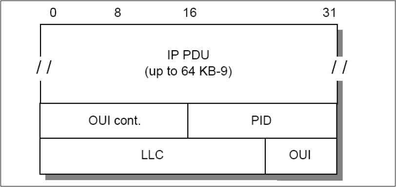
The following figure shows the payload format for routed IP PDUs (Figure 2-8).
Figure 2-8 CPCS-PDU payload format for IP PDUs
Where:
|
IP PDU |
Normal IP datagram, starting with the IP header. |
|
LLC |
A 3-byte LLC header with the format DSAP-SSAP-Ctrl. For IP data, it is set to 0xAA-AA-03 to indicate the presence of a SNAP header. The Ctrl field always has the value 0x03, specifying Unnumbered Information Command PDU. |
|
OUI |
The 3-byte Organizationally Unique Identifier (OUI) identifies an organization that administers the meaning of the following 2-byte Protocol Identifier (PID). To specify an EtherType in PID, the OUI has to be set to 0x00-00-00. |
|
PID |
The Protocol Identifier (PID) field specifies the protocol type of the following PDU. For IP datagrams, the assigned EtherType or PID is 0x08-00. |
Table 2-5 CPCS-PDU payload format for IP PDUs
There is no mapping from IP broadcast or multicast addresses to ATM broadcast or multicast addresses available. But there are no restrictions for transmitting or receiving IP datagrams specifying any of the four standard IP broadcast address forms as described in RFC 1122. Members, upon receiving an IP broadcast or IP subnet broadcast for their LIS, must process the packet as though addressed to that station.
Another approach to provide a migration path to a native ATM network is ATM LAN emulation. ATM LAN emulation is still under construction by ATM Forum working groups. For the IETF approach, see 2.10.2, “Classical IP over ATM” on page 50. There is no ATM Forum implementation agreement available covering virtual LANs over ATM, but there are some basic agreements on the different proposals made to the ATM Forum. The following descriptions are based on the IBM proposals.
The concept of ATM LAN emulation is to construct a system such that the workstation application software “thinks” it is a member of a real shared medium LAN, such as a token ring. This method maximizes the reuse of existing LAN software and significantly reduces the cost of migration to ATM. In PC LAN environments, for example, the LAN emulation layer can be implemented under the NDIS/ODI-type interface. With such an implementation, all the higher layer protocols, such as IP, IPX, NetBIOS, and SNA, can be run over ATM networks without any change.
Refer to Figure 2-9 for the implementation of token ring and Ethernet.
Figure 2-9 Ethernet and token-ring LAN emulation
LAN emulation layer (workstation software)
Each workstation that performs the LE function needs to have software to provide the LE service. This software is called the LAN emulation layer (LE layer). It provides the interface to existing protocol support (such as IP, IPX, IEEE 802.2 LLC, NetBIOS, and so on) and emulates the functions of a real, shared medium LAN. This means that no changes are needed to existing LAN application software to use ATM services. The LE layer interfaces to the ATM network through a hardware ATM adapter.
The primary function of the LE layer is to transfer encapsulated LAN frames (arriving from higher layers) to their destination either directly (over a direct VC) or through the LE server. This is done by using AAL5 services provided by ATM.
Each LE layer has one or more LAN addresses as well as an ATM address.
A separate instance (logical copy or LE client) of the LE layer is needed in each workstation for each different LAN or type of LAN to be supported. For example, if both token-ring and Ethernet LAN types are to be emulated, you need two LE layers. In fact, they will probably just be different threads within the same copy of the same code, but they are logically separate LE layers. Use separate LE layers also if one workstation needs to be part of two different emulated token-ring LANs. Each separate LE layer needs a different MAC address, but can share the same physical ATM connection (adapter).
LAN emulation server
The basic function of the LE server is to provide directory, multicast, and address resolution services to the LE layers in the workstations. It also provides a connectionless data transfer service to the LE layers in the workstations, if needed.
Each emulated LAN must have an LE server. It would be possible to have multiple LE servers sharing the same hardware and code (via multithreading), but the LE servers are logically separate entities. As for the LE layers, an emulated token-ring LAN cannot have members that are emulating an Ethernet LAN. Thus, an instance of an LE server is dedicated to a single type of LAN emulation. The LE server can be physically internal to the ATM network or provided in an external device, but logically it is always an external function that simply uses the services provided by ATM to do its job.
Default VCs
A default VC is a connection between an LE layer in a workstation and the LE server. These connections can be permanent or switched.
All LE control messages are carried between the LE layer and the LE server on the default VC. Encapsulated data frames can also be sent on the default VC.
The presence of the LE server and the default VCs is necessary for the LE function to be performed.
Direct VCs
Direct VCs are connections between LE layers in the end systems. They are always switched and set up on demand. If the ATM network does not support switched connections, you cannot have direct VCs, and all the data must be sent through the LE server on default VCs. If there is no direct VC available for any reason, data transfer must take place through the LE server. (There is no other way.)
Direct VCs are set up on request by an LE layer. (The server cannot set them up, because there is no third-party call setup function in ATM.) The ATM address of a destination LE layer is provided to a requesting LE layer by the LE server. Direct VCs stay in place until one of the partner LE layers decides to end the connection (because there is no more data).
Initialization
During initialization, the LE layer (workstation) establishes the default VC with the LE server. It also discovers its own ATM address, which is needed if it is to later set up direct VCs.
Registration
In this phase, the LE layer (workstation) registers its MAC addresses with the LE server. Other things, such as filtering requirements (optional), can be provided.
Management and resolution
This is the method used by ATM endstations to set up direct VCs with other endstations (LE layers). This function includes mechanisms for learning the ATM address of a target station, mapping the MAC address to an ATM address, storing the mapping in a table, and managing the table.
For the server, this function provides the means for supporting the use of direct VCs by endstations. This includes a mechanism for mapping the MAC address of an end system to its ATM address, storing the information, and providing it to a requesting endstation.
This structure maintains full LAN function and can support most higher layer LAN protocols. Reliance on the server for data transfer is minimized by using switched VCs for the transport of most bulk data.
2.10.4 Classical IP over ATM versus LAN emulation
These two approaches to providing an easier way to migrate to ATM were made with different goals in mind.
Classical IP over ATM defines an encapsulation and address resolution method. The definitions are made for IP only and not for use with other protocols. So if you have applications requiring other protocol stacks (such as IPX or SNA), IP over ATM will not provide a complete solution. However, if you only have TCP or UDP-based applications, this might be the better solution, because this specialized adaptation of the IP protocol to the ATM architecture is likely to produce fewer inefficiencies than a more global solution. Another advantage of this implementation is the use of some ATM-specific functions, such as large MTU sizes.
The major goal of the ATM Forum‘s approach is to run layer 3 and higher protocols unchanged over the ATM network. This means that existing protocols, for example, TCP/IP, IPX, NetBIOS, and SNA, and their applications can use the benefits of the fast ATM network without any changes. The mapping for all protocols is already defined. The LAN emulation (LANE) layer provides all the services of a classic LAN; thus, the upper layer does not know of the existence of ATM. This is both an advantage and a disadvantage, because the knowledge of the underlying network could be used to provide a more effective implementation.
In the near future, both approaches will be used depending on the particular requirements. Over time, when the mapping of applications to ATM is fully defined and implemented, the scheme of a dedicated ATM implementation might be used.
2.11 Multiprotocol over ATM (MPOA)
The objectives of MPOA are to:
Although the name is multiprotocol over ATM, the actual work being done at the moment in the MPOA subworking group is entirely focused on IP.
MPOA represents the transition from LAN emulation to direct exploitation of ATM by the internetwork-layer protocols. The advantages are:
The MPOA solution has the following benefits over both Classical IP (RFC 2225) and LAN emulation solutions:
2.11.2 MPOA logical components
The MPOA solution consists of a number of logical components and information flows between those components. The logical components are of two kinds:
|
MPOA server |
MPOA servers maintain complete knowledge of the MAC and internetworking layer topologies for the IASGs they serve. To accomplish this, they exchange information among themselves and with MPOA clients. |
|
MPOA client |
MPOA clients maintain local caches of mappings (from packet prefix to ATM information). These caches are populated by requesting the information from the appropriate MPOA server on an as-needed basis. The layer 3 addresses associated with an MPOA client represent either the layer 3 address of the client itself, or the layer 3 addresses reachable through the client. (The client has an edge device or router.) An MPOA client will connect to its MPOA server to register the client‘s ATM address and the layer 3 addresses reachable by the client. |
Table 2-6 The MPOA logical components
2.11.3 MPOA functional components
The mapping between the logical and physical components are split between the following layers:
The MPOA solution will be implemented into various functional groups that include:
A coresident proxy LEC function is optional.
Within an IASG, LAN emulation is used as a transport mechanism to either traditional devices or LAN emulation devices, in which case access to a LEC is required. If the AHFG will not be communicating with LANE or other devices, a co-resident LEC is not required.
Note: One or more of these functional groups can co-reside in the same physical entity. MPOA allows arbitrary physical locations of these groups.
The MPOA system operates as a set of functional groups that exchange information in order to exhibit the desired behavior. To provide an overview of the MPOA system, the behavior of the components is described in a sequence order by significant events:
| Configuration |
Ensures that all functional groups have the appropriate set of administrative information. |
| Registration and discovery |
Includes the functional groups informing each other of their existence and of the identities of attached devices and EDFGs informing the ICFG of earlier devices. |
| Destination resolution |
The action of determining the route description given a destination internetwork layer address and possibly other information (for example, QoS). This is the part of the MPOA system that allows it to perform cut-through (with respect to IASG boundaries). |
| Data transfer |
To get internetworking layer data from one MPOA client to another. |
| Intra-IASG coordination |
The function that enables IASGs to be spread across multiple physical interfaces. |
| Routing protocol support |
Enables the MPOA system to interact with traditional internetworks. |
| Spanning tree support |
Enables the MPOA system to interact with existing extended LANs. |
| Replication Support |
Provides for replication of key components for reasons of capacity or resilience. |
Table 2-7 MPOA operation
2.12 RFCs relevant to this chapter
The following RFCs provide detailed information about the connection protocols and architectures presented throughout this chapter:
[000] TCP/IP Tutorial and Technical Overview
http://www.redbooks.ibm.com/
[001] Digital Equipment Corporation
http://en.wikipedia.org/wiki/Digital_Equipment_Corporation
1957年,肯·奥尔森(Ken Olson)与哈兰·安德森(Harlan Andersen)创立迪吉多,资本为10万美元,其中70%的股权由名为“美国研发公司”(American Research and Development Corporation)的一家风险投资公司所持有。
配备了两台磁带机的迪吉多“PDP-11/40”迷你电脑在公司创立之前,奥尔森和安德森曾为 Lincoln Labs设计过AN/FSQ-7、TX-0及TX-2的电脑组成部份。凭著这份经验,奥尔森和安德森希望可以制作出一部拥有自己品牌的迷你电脑。最终,迪吉多靠着自身的PDP系列电脑,开始在国际打出名堂。
1980年代,迪吉多生产的VAX系列迷你电脑成为备受全球各大企业及大专院校推崇的电子产品之一。
1998年,迪吉多被康柏电脑收购,Alpha微处理器成为康柏电脑的高阶服务器市场的主力产品。
2002年,康柏电脑(连同旗下的迪吉多)被惠普公司并购。
http://en.wikipedia.org/wiki/Logical_link_control
Figure 2-1 ARP Frame formats for Ethernet and IEEE 802.3
Figure 2-2 ARP: IEEE 802.2 LSAP header
Figure 2-3 ARP: IEEE 802.2 SNAP header
Figure 2-4 IP and ARP over FDDI
Figure 2-5 PPP encapsulation frame
Figure 2-6 Frame relay packet format
Figure 2-7 AAL5 CPCS-PDU format
Figure 2-8 CPCS-PDU payload format for IP PDUs
Figure 2-9 Ethernet and token-ring LAN emulation
Table 2-1 PPP encapsulation fields
Table 2-2 SONET speed hierarchy
Table 2-4 AAL5 CPCS-PDU format
Table 2-5 CPCS-PDU payload format for IP PDUs
Table 2-6 The MPOA logical components
标签:des style blog http ar io color os sp
原文地址:http://www.cnblogs.com/humphrycc/p/4160316.html