As most of you know by now, the Raspberry Pi is a fantastic little Linux box with many wonderful features. Over the last year and a bit that the Raspberry Pi has been out in the wild, users have discovered that this little computer can do almost anything – and without crippling your wallet!
However, Raspberry Pi‘s very small price tag and form factor mean that the Rasp Pi has had to do without some of the home comforts normally found on a laptop or desktop computer – one of these comforts is a power-on and -off switch. The only safe way to shut down the Raspberry Pi is to do it manually using the graphical desktop interface – either with the LXDE power management window or by opening a terminal window and typing in a shutdown or reset command.
Although an orderly shutdown is not a huge amount of work, it often gets overlooked or forgotten, and some users just pull out the microUSB power plug while the system is running. Doing this repeatedly could very easily lead to a corrupted SD card, a completely broken SD card, or even damage to the Raspberry Pi itself.
Why risk the annoyance and cost of a broken SD card when you can very easily employ a number of power management options? In this article, I describe some options for adding a power switch to your Raspberry Pi. I‘ll show you how to implement
- a reset switch – use this switch to start the system or reboot in case of a crash;
- a safe shutdown switch – equivalent to shutting down the GUI or entering the
shutdown command in the terminal window, the switch triggers a Python script that initiates an orderly shutdown for the system;
- a full On/Off power switch – a more complete solution that shuts down the system and also shuts off power to the Raspberry Pi. I‘ll describe the hardware configuration then show you how to use the switch to trigger a script that initiates a safe shutdown.
Reset Switch
Parts and Tools for Reset Switch
The reset switch will only work with the Rev 2 Raspberry Pi boards. You will need [5]:
- One-row, two-way male header, 2.54mm (RS part 251-8086 or similar)
- Reset switch from an old computer (Maplin A19GL, or similar)
- Soldering iron and solder
When the Revision 2 Raspberry Pi Model B board was released around the end of 2012, it introduced a number of improvements and changes to the Revision 1 board. Among these changes was the introduction of the P6 header, which is located beside the HDMI port on Raspberry Pi Rev 2 boards. (All Model A boards are Rev 2 boards also.)
The purpose of the P6 header is to enable a reset of the Raspberry Pi‘s CPU. The reset switch can restart the system, but it does not provide the safe shutdown described in the next section; therefore, it shouldn‘t be used to shut down or reboot a system that is already running. To perform a reset, all you have to do is short the two connections of the header together. Although you have a number of ways to do this, in my opinion, the best way is with some header pins and a momentary switch.
As you can see in Figure 1, the header is not populated with any header pins by default (because things like header pins would add cost); however, it is very simple to add these pins with some basic soldering. All you need is a standard two-way, one-row 2.54mm male header (Figure 2). Place the pins into the holes of the P6 header, grab your soldering iron, and secure them in place.
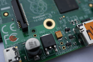 Abbildung 1: The P6 header on Raspberry Pi Rev 2 supports a handy reset feature.
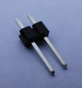 Abbildung 2: Connect to the P6 with a standard two-way, one-row male header.
If you haven‘t soldered for a while and are feeling a bit uneasy about soldering directly on your Raspberry Pi, you will find a number of great guides online; my personal favorites are the "Soldering is Easy" comic [1] or the SparkFun soldering guide [2].
Once you have successfully soldered the pins to the board, you are ready to connect the reset switch and test it out (Figure 3).
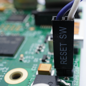 Abbildung 3: Attach the switch cable to the header to test the reset switch.
You now have a fully functional reset switch (Figure 4). All you need to do is apply a short press and the Rasp Pi will perform a soft reset. An added bonus of this switch is that when the Rasp Pi is in the shutdown or "halt" state (plugged in with power applied to board, but after having been shutdown from within the OS), you can also use this switch to wake it up.
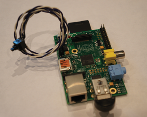 Abbildung 4: Use this simple switch to start or reboot your Raspberry Pi.
Safe Shutdown Switch
Parts for Safe Shutdown Switch
To build the safe shutdown switch, you will need [5]:
- 1kohm resistor
- 10kohm resistor
- Momentary switch
- Breadboard
- Jumper wires, both male-to-male and male-to-female
The reset switch is a very useful feature of the Rev 2 board; however, it does not allow for a safe shutdown of the Rasp Pi. A safe shutdown is very important to avoid causing SD card errors. Fortunately, it is possible to create a GPIO-connected switch, which, at the press of a button, allows you to ensure that the Rasp Pi has fully and correctly shut down before you pull the power plug. Tapping a safe shutdown switch is a far easier and cooler way to turn off a computer than opening a terminal window and typing:
sudo shutdown -h now
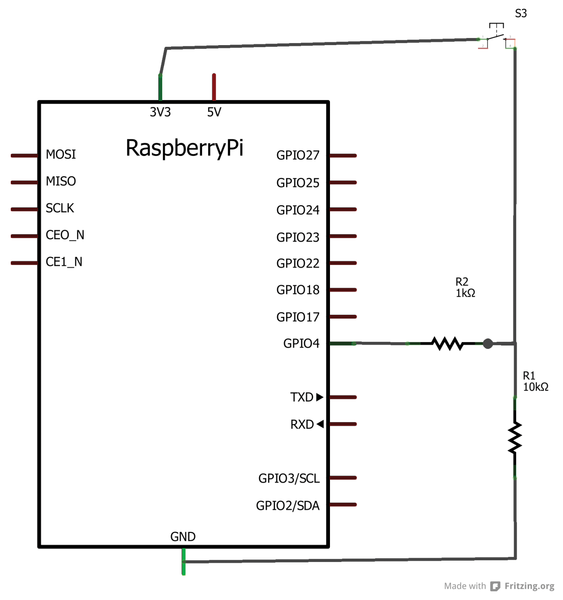
The schematic in Figure 5 shows the layout for a safe shutdown switch for use with the Raspberry Pi. You might be wondering why you can‘t just connect the 3.3V pin, via a switch, to a GPIO pin set as an input; however, if you were to do this with no resistors or other circuitry, the circuit would either be very unreliable or not function at all.
 Abbildung 5: Schematic for the safe shutdown switch.
The problem is that, when the input pin is not connected to anything (because the switch is open), it will "float" – its value will change a lot because of interference from the mains (and other noise) or similar phenomena. Thus, the input state will not remain at a defined voltage level. The Rasp Pi would not be able to detect reliably whether the input was in a high or low state.
You can address this problem with either a pull-up or pull-down resistor. In this example, I have used a pull-down resistor. As you can see, the GPIO4 pin is connected to ground via a 10kohm resistor (R1). Ten kiloohms is a large enough value that the 3.3V signal source is able to overcome the pull-down resistor and continue on its way to GPIO4. If the interference and noise became larger, then a smaller resistor would be needed, but don‘t go too low, or the signal source will not be able to defeat the pull-up/down resistor.
For this reason, when implementing pull-up/down resistors, it is typical to use a resistor value that is around 10 times the source impedance – in most Rasp Pi applications, 10kohm should be suitable. The resistor R2 is a current-limiting resistor used to protect the GPIO pin and make the circuit safer, which is important because if you accidentally were to set GPIO4 as an output, pushing the button would cause a short circuit directly between 3.3V and ground. To make it easier for you to assemble your project on a breadboard, I have included a simple breadboard layout. The complete breadboard configuration is shown in Figure 6.
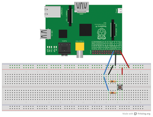 Abbildung 6: Safe shutdown breadboard configuration.
A press of the switch will initiate a safe shutdown of the Raspberry Pi, which will eventually end up in the halt state. If you want to start the Raspberry Pi up again, it is possible to wake it from a shutdown by simply pressing the reset switch described in the preceding section. You‘ll need one of the safe shutdown scripts in the Code Examples section for the safe shutdown switch to work.
Full On/Off Power Switch
Parts for Full On/Off Switch
To build the full On/Off switch, you‘ll need the following [5]:
- 2 x 1kohm resistor
- 2 x 10kohm resistor
- 2 x 22kohm resistor
- 3 x Momentary switch
- 2 x NPN transistor (BC548 used here)
- 2 x diode (1N4001 used here)
- 1 x 220µF capacitor (Panasonic ECA-0JM221I used here)
- 1 x 5V SPDT relay (Omron G5V-1-5DC used here)
- 1 x LED (3mm red used here)
- 1 x 2-meter USB A to USB microB cable (24 AWG or higher recommended)
- Breadboard
- Jumper wires, both male-to-male and male-to-female
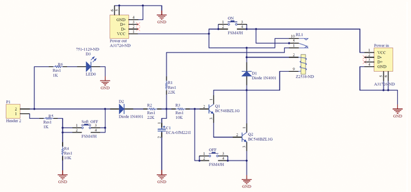
The reset and soft shutdown switch together form a very useful way to turn the Raspberry Pi on and off. However, one problem remains: when the Raspberry Pi is in the shutdown state, it still uses a considerable amount of power and leaves the power LED lit, so it is therefore not particularly suitable to certain applications. This final section of the article looks at a way to create a fully functional On/Off power switch that works much like the switch on your desktop or laptop computer (Figure 7). This solution includes an On switch, a hard Off switch, and a soft shutdown switch, as well as an LED. The solution connects in-line with your 5V microB USB power supply for the Rasp Pi using a spliced USB cable.
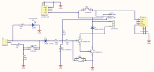 Abbildung 7: Schematic for the full On/Off power switch.
The breadboard configuration is shown in Figure 8. Take a 2-meter-long USB A--to--USB microB cable, cut it in half, strip the positive and ground cables back, and then use the full-size A plug on the input and the microB plug on the output. You can then plug the microB plug into the standard Rasp Pi power input receptacle (top right of the breadboard drawing) and plug the full-size A plug into the USB port on your power supply. (This assumes you have a power supply with a detachable USB cable; if not, you could always use your detachable phone or tablet charger.) The blue wire connects from the breadboard to pin 7 on the Rasp Pi, and the orange wire connects to pin 8. If you have any problems with a voltage drop across this circuit, I recommend buying a 5.25V power supply. These power supplies are custom made for use with the Raspberry Pi, and you can get these either from ModMyPi [3] or Pi Supply [4].
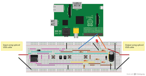 Abbildung 8: Breadboard configuration for the On/Off power switch.
The circuit is fairly simple:
- When the relay (RL1 in the schematic) is in the off state, but 5V is supplied to the input, the voltage travels through the relay and then through a 22kohm resistor to charge the capacitor.
- Once the voltage across the capacitor is high enough, it turns on transistors 1 and 2 (Q1 and Q2 in schematic), which connects one end of the relay coil to ground.
- When the power-on button is pressed momentarily, the relay is instantly activated. This causes power to be supplied to the output and, as the relay switches contact from pin 1 to pin 10, it also causes the capacitor to slowly discharge. Eventually, after about two minutes, the capacitor will drain to a level where it can no longer keep the transistors in their energized state, which will cause the relay to change back to its original state (removing power from the Rasp Pi). Obviously, this is not what you want, and the following aspects of the circuit allow it to maintain power to the Rasp Pi.
- Once the Pi is booted up, pin 8 (or another pin of your choosing – see code examples below) will begin to output 3.3V. This output will turn the LED on and it will also take over the responsibility for keeping the capacitor charged (allowing the transistors to remain energized and the circuit to maintain power to the Rasp Pi). Additionally it provides a 3.3V source for the safe shutdown switch – the safe shutdown switch routes this 3.3V back to a GPIO pin set to an input which, in turn, triggers a safe shutdown to be called within the system.
- When a shutdown is initiated (either using the safe shutdown switch provided, a terminal window, or the built-in LXDE functionality), the GPIO output (pin 8 – or another pin of your choosing) will be dropped. This will cause the capacitor to begin discharging, and after about two minutes (as explained in step 3), the relay will switch to its initial state and the power to the Rasp Pi will be dropped.
- You can then start the Rasp Pi again using the On button.
The two-minute delay explained in step 3, unlike in other power management solutions, also has the benefit of allowing a system reboot, which can be initiated using a restart button, as explained above in the restart switch section, or in software.
The two-minute delay can be altered by using a different capacitor size – if you want a longer delay, you could replace the 220µF capacitor with something a bit bigger, and if you want a shorter delay, you could replace the capacitor with something a bit smaller.
Using the hard Off switch should be avoided unless absolutely necessary because of the potential for corruption to the SD card with a hard power down. An example of when this might be necessary is if the Rasp Pi has frozen and will not respond. Care should be taken, however, to make sure that the processor activity indicator LED on the Rasp Pi is not flashing when you press the Off switch. If this LED is not flashing (or on solid) it should mean little or no writing to the SD card is occurring, which should reduce the likelihood of a corrupted SD card.
Code Examples
For both the safe shutdown switch and the full On/Off power switch, some code is needed for the safe shutdown functionality to work correctly. The switch causes the script to initiate the shutdown. In Python you have two ways to implement this solution – with a while loop or using interrupts. Open the Python IDE and paste in the code from either the interrupt or while loop options described in the following sections [5]. A later section describes how to load a Python file during the boot process.
Interrupts
Using an interrupt-based script is the best way to enable the soft shutdown feature of the Pi Supply switch. Using interrupts improves the efficiency of the code and minimizes load on the CPU compared with the while loop. The code for the interrupt method is shown in Listing 1. See the comments in the listing for a description of what the code is doing.
01 # Import the modules to send commands to the system and access GPIO pins
02 from subprocess import call
03 import RPi.GPIO as gpio
04
05 # Define a function to keep script running
06 def loop():
07    raw_input()
08
09 # Define a function to run when an interrupt is called
10 def shutdown(pin):
11     call(‘halt‘, shell=False)
12
13 gpio.setmode(gpio.BOARD) # Set pin numbering to board numbering
14 gpio.setup(7, gpio.IN) # Set up pin 7 as an input
15 gpio.add_event_detect(7, gpio.RISING, callback=shutdown, bouncetime=200) # Set up an interrupt to look for button presses
16
17 loop() # Run the loop function to keep script running
while Loop
A while loop is a basic fundamental of almost every programming language in existence, and it is a very useful tool. The code in Listing 2 has the same end result as the interrupt-based script – it allows the safe shutdown of your Rasp Pi, but it does so in a significantly more resource-hungry way. On the other hand, the while loop is a more basic piece of code that is perhaps easier to understand. Although I recommend using the interrupt-based code, I include the while loop approach also, because it works fine, and some people might prefer to use this code (or at least play with it and try to get their head around how it works).
01 # Import the libraries to use time delays, send os commands and access GPIO pins
02 import RPi.GPIO as GPIO
03 import time
04 import os
05
06 GPIO.setmode(GPIO.BOARD) # Set pin numbering to board numbering
07 GPIO.setup(7, GPIO.IN) # Setup pin 7 as an input
08 while True: # Setup a while loop to wait for a button press
09    if(GPIO.input(7)): # Setup an if loop to run a shutdown command when button press sensed
10    os.system("sudo shutdown -h now") # Send shutdown command to os
11    break
12    time.sleep(1) # Allow a sleep time of 1 second to reduce CPU usage
Loading a Python File During Boot
After you have entered the interrupt-based or while-loop-based code into the Python IDE, you need to create a folder called PiSupply in the /home/pi directory. Save the code (either Listing 1 or 2, whichever you choose) in the newly created folder at /home/pi/PiSupply, naming the file softshut.py or something similar. Then, open an LXTerminal session and use the Nano text editor to add some code to enable the Python script you just created to run when the Rasp Pi boots up. Type
sudo nano /etc/rc.local
and then add the line
python /home/pi/PiSupply/softshut.py
before the line that says
exit 0
Press Ctrl+X to exit the Nano editor and, when prompted, press Y and then Enter to save the file you just edited. The file name softshut.py, and the folder names and locations, can be whatever you want them to be, but you need to make sure you maintain the names consistently. Listings 1 and 2 use physical pin 7 on the GPIO header, which corresponds to the fourth pin from the right on the top row (when looking down on the Pi from above with the RCA video connector socket facing toward you). You can change this code to use any other GPIO pin; I just chose pin 7 because it is next to physical pin 8, which is the required pin to use for the automatic power supply switching without any additional code.
Replacing Pin 8 (TXD)
It is possible to add some code to the preceding examples to change to a pin other than physical pin 8 for the main automatic power-off functionality of the full On/Off power switch. You might want to use this code if you are using pin 8 as the serial TX in part of a serial connection. The code to add is shown in Listing 3.
Changing from the Default Pin
01 keep_powered_pin = 18 # Default pin is 8
02
03 # Pin to pull high to keep the Pi Supply giving power
04 gpio.setup(keep_powered_pin, gpio.OUT, initial=gpio.HIGH)
As you can see, the code in Listing 3 changes the pin from the default pin 8 (which requires no code) to pin 18. You can change this pin number to any GPIO pin that is capable of being configured as an output.
Add this snippet to either the while loop or the interrupt-based script. I recommend adding it after the line in Listing 1 that says:
import RPi.GPIO as gpio
In Listing 2, add the pin change code after line 4, import os.
Conclusion
The options described in this article should provide a solution for most Raspberry Pi power management needs. One great thing about the Raspberry Pi is that it lets your imagination run wild. If you look at these solutions and think, "I wish I could add this functionality here," why not search the forums, blogs, and various other resources available in the Raspberry Pi community and have a play with your ideas. If nothing else, you will have fun in the process.