标签:des style blog http color strong
BACKGROUND
Many algorithms on a graphics processing unit (GPU) may benefit from doing a query in a hierarchical tree structure (including quad-trees, oct-trees, kd-trees, R-trees, and so forth). However, these trees can be very deep, whereby traversing the tree uses many fetches from memory to reach the "leaf" node where the data typically resides. For example, to traverse a tree in the pixel shader, the traversal typically starts at the root of the tree, with many memory fetches needed to work down to a leaf to retrieve the actual data for the query point.
Consider a scenario in which lightmap data is stored in a sparse quad-tree instead of using a traditional texture map; in such a tree, the empty areas of the texture take up no memory, and areas of low variance can use lower resolutions. An algorithm may query lightmap data in the pixel shader, replacing a traditional texture map lookup. The pixel shader queries the 2D quad-tree using a UV-coordinate as with normal 2D textures. If a hypothetical quad tree covers the equivalent of a typical high definition screen resolution and the total depth of the tree is twelve, e.g. 1920×1080 multiplied by 12 fetches per pixel=24,883,200. This is a significant computational expense, and any reduction in the number of fetches needed to locate needed data is highly desirable.
SUMMARY
Briefly, various aspects of the subject matter described herein are directed towards a technology by which a hierarchal tree of nodes is traversed by stages a graphics pipeline, including a first stage having a first traversal mechanism configured to traverse at least some of a hierarchical tree structure of data in a coarse traversal until a first state is detected. A second traversal mechanism traverses at least some of the hierarchical tree structure in a fine traversal (relative to the coarse traversal) until a second state is detected, in which the fine traversal uses state information from the coarse traversal to avoid traversing at least some nodes traversed in the coarse traversal. One or more additional stages corresponding to additional coarseness and/or fineness may be present in the pipeline and traverse the tree in coarse-to-fine traversal operations.
In one aspect, a higher stage in a graphics pipeline traverses a hierarchal tree structure in a higher stage traversal until a stopping criterion is met. State information corresponding to the higher stage traversal is provided to a lower stage in the graphics pipeline. The lower stage, upon receiving the state information, uses the state information to determine one or more starting points for a lower stage traversal, which comprises traversing the hierarchal tree of nodes based upon the one or more starting points until another stopping criterion is met.
DETAILED DESCRIPTION
Various aspects of the technology described herein are generally directed towards performing parts of tree traversal at different stages in the graphics pipeline, in a coarse-to-fine fashion. In one aspect, each coarser stage in the GPU pipeline does as much of the tree-traversal as possible (limited by the "coarseness" of that pipeline stage), and passes on the intermediate state of the traversal to the next (finer-grained) stage, which refines it further. As will be understood, the technology exploits the hierarchical coarse-to-fine nature of the graphics pipeline, by linking it to the hierarchical coarse-to-fine nature of the trees.
In general, the technology herein leverages pixel-to-pixel coherency, in which two adjacent pixels represented in a tree structure are likely to share a large portion of the path from the root, to avoid repeating work for each pixel. For example, moving some of the traversal work to the geometry shader stage of the graphics pipeline (which runs per-triangle, instead of per-pixel) instead of having the pixel shader stage perform the entire traversal, results in considerable work being shared for pixels.
It should be understood that any of the examples herein are non-limiting. For one, while examples are described in the hierarchical nature of object rendering on a GPU, a similar strategy may be employed for more general tasks, for three-dimensional or two-dimensional objects, and/or for various types of hierarchical tree structures. As such, the present invention is not limited to any particular embodiments, aspects, concepts, structures, functionalities or examples described herein. Rather, any of the embodiments, aspects, concepts, structures, functionalities or examples described herein are non-limiting, and the present invention may be used various ways that provide benefits and advantages in computing and tree traversal in general.
FIG. 1 shows a block diagram comprising components of an example graphics pipeline?102?that is configured to traverse a tree?104?and return results in a response (e.g., a query response)?106. Note that for simplicity, only certain example stages of the graphics pipeline are shown in FIG. 1; exemplified are a hull shader stage?108, a geometry shader stage?110, and a pixel shader stage?112. For example, contemporary GPUs can process larger primitives (called "patches") than geometry primitives (quad or triangle primitives); such patch processing corresponds to the hull shader stage of FIG. 1. Other stages, e.g., a vertex shader stage, a tessellator stage, a domain shader stage, and rasterizer stage may be present in a given implementation, and may benefit from the concepts described herein.
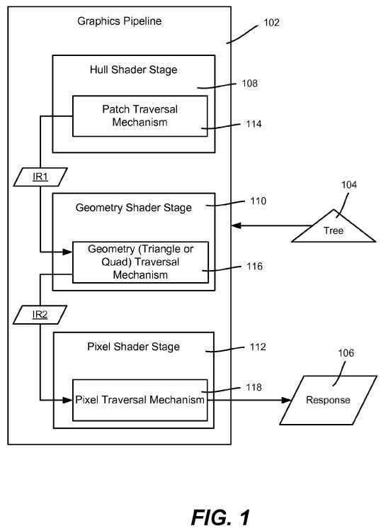
The illustrated stages?108,?110?and?112?are programmed to each contain a traversal mechanism, represented by blocks?114,?116?and?118, respectively. The stages can communicate data to one another, such that a higher level traversal mechanism is able to pass intermediate state results (IR1?or IR2) to the next lower traversal mechanism.
As generally described herein, in an implementation with patch-processing capabilities, some of the traversal may be performed on the patch by the patch traversal mechanism?114, with the resulting intermediate state results IR1?(e.g., comprising a starting node or nodes for that next level) passed down to the geometry traversal mechanism?116.
In general, the patch traversal mechanism traverses the tree downwards, until a node is reached that no longer contains the entire patch data under that node. This can be stated as detecting child nodes that intersect. The intermediate state may correspond to one or more nodes, with a predetermined threshold set for when to stop traversing, e.g., stop once there are more than N nodes (typically a relatively small number) that intersect, and send state information comprising the parent node or all the child nodes (if N was set to one), or the appropriate subset of child nodes that intersect if N is greater than one. The next stage in the hierarchy loops through paths starting with the node or nodes passed, thereby ignoring ones not intersected, and traversing nodes that intersect). Note that in less structured trees where child nodes can overlap (e.g. bounding-box trees), it is common for a region to touch more than one child node, whereby sending multiple nodes may be beneficial.
As can be readily appreciated, depending on the exact type of tree used, it also may be beneficial to have some of the nodes, particularly near the root, be "loose," such that the children overlap slightly. This avoids having to stop traversal early because a primitive slightly overlaps child nodes.
When the intermediate state is received in the example of FIG. 1 wherein the next stage is the geometry shader stage?110, the geometry traversal mechanism?116?does further traversal on the quad or triangle primitive, until intersection is detected. Note that the number of intersecting nodes that stop traversal at this stage need not be the same as the number at the higher stage. When traversal is stopped, the geometry traversal mechanism?116passes down the intermediate results IR2?to the pixel traversal mechanism?118, which starts its traversal at the passed node or nodes and traverses down to the leaf node. As is understood, even if starting the whole traversal operation at the geometry shader stage (in an implementation without patch-processing capabilities, for example), benefits are obtained because the geometry shader stage is coarser than the pixel shader stage.
As can be readily appreciated, the technology may be used at any relevant hierarchical levels. Further, coarse-to-fine traversal also may be extended above the patch processing stage. For example, if dealing with a tree whose root node covers more than just one object, some tree traversal on the CPU may be performed.
Turning to an example, consider processing a sparse quad-tree as generally represented in FIGS. 2-4A. A suitable example tree may be considered in which on average there are about 8×8 pixels per triangle, such that a quad-tree needs about three levels to cover a whole triangle. If the tessellator stage (between the hull shader stage and the geometry shader stage) outputs, on average, about 16×16 triangles per patch, then four levels are needed to cover the entire patch. If the quad tree covers the equivalent of 4090×4096 pixels, then the total depth is twelve.
Instead of starting traversal at the pixel shader stage, described herein is first performing a tree traversal at a higher stage, e.g., on the "patch" in FIG. 1, before tessellation. Traversal continues as far down the tree as possible until the patch is no longer entirely covered by a child node, that is, intersection is detected. Consider in this example that traversal stops at the first detected intersection.
This is represented in FIGS. 2 and 3, in which there is a patch P intersecting against the root node N0?of a quad-tree. In this patch processing part of the example, the patch P‘s representative data is contained entirely within the lower-right child node N4?of the root node N0, so the query process continues traversing down into that child node N4.
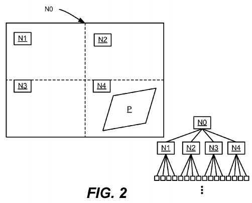
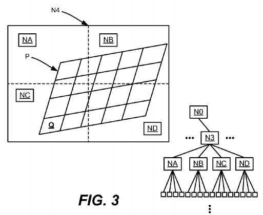
FIG. 3 is a zoomed-in representation of the lower-right child node N4. At this level, the patch P is not covered entirely by one child node, and thus no further traversal is performed at the patch-level.
Note that in the example of FIGS. 2-4A, the size of the patch P is exaggerated to facilitate illustration, so that there is one traversal step in each of the patch and geometry (quad/triangle) stages. In a typical actual tree, there are likely more traversal steps in these stages, (whereby more operations can be skipped in the final pixel shader stage).
As described herein, the patch traversal mechanism sends the intermediate state (node N4‘s information) down for processing each tessellation primitive at the geometry shader stage. Note that the primitives in FIG. 3 are represented as quads, however they instead may be triangles, for example.
In FIG. 3, consider the quad geometry primitive labeled Q. In the geometry shader stage?110, this quad Q is intersected against the node NC. Because the quad Q is entirely covered by the lower left quad-tree child node NC, that child node NC can be traversed by the geometry traversal mechanism116.
FIGS. 4A and 4B focus on the lower-left quad Q; FIG. 4B is a zoomed in representation of FIG. 4A. As can be seen, at this level the quad Q is no longer entirely covered by a single child node, so no more traversal can be performed in the geometry shader stage?110, and the current traversal state information is sent down to the pixel traversal mechanism?118.
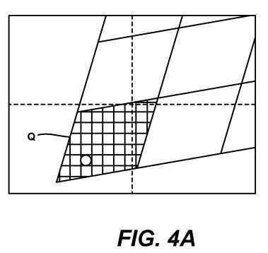
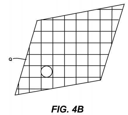
FIG. 4B is zoomed-in to represent the lower-left child of the previous node in a more easily viewed manner. The pixel traversal mechanism?118?of the pixel shader stage?112?traverses the individual pixels of the quad Q down to the leaf node of the tree, to retrieve the requested data to return as the query results?106.
In the example twelve-level tree described above (about 8×8 pixels per triangle, about 16×16 triangles per patch), the per-patch traversal needs 12?4?3=5 fetches. Thus, the total number of fetches in coarse-to-fine processing may be five for the patch, then four for each of the 16×16 triangles in the patch, and then three for each of the 8×8 pixels in each triangle, totaling?50,181?fetches for the whole patch.
FIG. 5 is a flow diagram showing example steps taken to traverse a tree in a coarse-to-fine manner corresponding to the coarse-to-fine stages of a graphics pipeline. In the example of FIG. 5, traversal starts at the patch level.
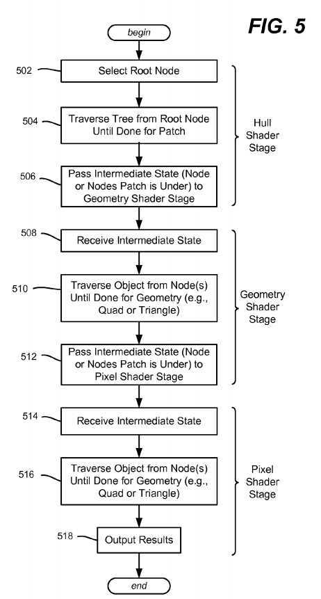
At steps?502?and?504, the patch traversal mechanism starts at the root node and traverses the nodes of the tree to find a lowest child node or (subset of child nodes) that contains the data of an entire patch under that node. When this node or subset of nodes is reached, at step?506?corresponding state information is passed (e.g., an identity of each node or nodes) to the geometry shader stage. Note that in the above exaggerated example of FIG. 2 this was only one child level lower, however with smaller patches in an actual, typical tree, the resolution is such that more than one lower node level typically will be reached in patch traversal, particularly if "loose" nodes are used.
With respect to such "loose" nodes, many types of tree structures may be tweaked with some amount of "looseness" to avoid having to stop traversal early on the coarse stages of the pipeline. For example, if a triangle barely intersects both children while traversing the tree in the geometry shader, instead of ending the traversal and performing the remaining traversal in the pixel shader, a tree with some looseness may have a child that entirely covers the triangle, even though other children intersect the triangle, whereby the process may continue traversing for at least one more level. Thus, instead of detecting intersection, the stopping criterion rule corresponds to whether a child node (or subset of nodes) contains the entire triangle data, regardless of whether there is some other intersection.
Steps?508,?510?and?512?are similar to steps?502,?504?and?506?and are not separately described, except to note that the geometry shader performs them on appropriate primitives, and that the traversal stopping criterion or rule may differ from that of the higher level. During the traversal, the paths taken by the geometry shader can start at the node (or set of nodes) passed to it from the higher level, because the entire patch of primitives is known to be under that node or subset of nodes.
Step?514?represents the pixel shader stage receiving the state information passed from the higher, geometry shader stage. Step?516?traverses the pixels starting from each node (which may be a single node) for each path taken. Step?518?outputs the results when the pixel traversal completes.
In sum, each level determines a lowest node or subset of child nodes during traversal that contains the primitive‘s data for that level, and passes that state information to the next lowest level. For example, the geometry shader, which may act on individual triangles or quads, keeps traversing until the triangle or quad is no longer entirely covered by a child node. Then the last-fully-covering node or set of nodes is passed on to the pixel shader, which traverses from that node (or each node of the set) down to the leaf nodes and retrieves the requested data.
Note that the above-described coarse-to-fine technology was only one example, and the technology is applicable to any hierarchical structure to be queried in a coherent fashion at one of the lower stages of the GPU pipeline. For example, a domain shader tree-lookup may be sped up by doing some traversal in the patch-level, in an analogous way. Other trees instead of a 2D quad-tree (e.g., queried by a traditional UV coordinate) may be similarly traversed, e.g., a 3D oct-tree may instead be traversed, using the world space position to query data. Other types of trees may be used to facilitate filtering (such as Random-Access trees), or others to achieve any other property of interest.
Example Operating Environment
FIG. 6 illustrates an example of a suitable computing and networking environment?600?into which the examples and implementations of any of FIGS. 1-4 may be implemented, for example. The computing system environment?600?is only one example of a suitable computing environment and is not intended to suggest any limitation as to the scope of use or functionality of the invention. Neither should the computing environment?600?be interpreted as having any dependency or requirement relating to any one or combination of components illustrated in the example operating environment?600.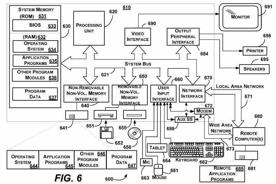
The invention is operational with numerous other general purpose or special purpose computing system environments or configurations. Examples of well known computing systems, environments, and/or configurations that may be suitable for use with the invention include, but are not limited to: personal computers, server computers, hand-held or laptop devices, tablet devices, multiprocessor systems, microprocessor-based systems, set top boxes, programmable consumer electronics, network PCs, minicomputers, mainframe computers, distributed computing environments that include any of the above systems or devices, and the like.
The invention may be described in the general context of computer-executable instructions, such as program modules, being executed by a computer. Generally, program modules include routines, programs, objects, components, data structures, and so forth, which perform particular tasks or implement particular abstract data types. The invention may also be practiced in distributed computing environments where tasks are performed by remote processing devices that are linked through a communications network. In a distributed computing environment, program modules may be located in local and/or remote computer storage media including memory storage devices.
With reference to FIG. 6, an example system for implementing various aspects of the invention may include a general purpose computing device in the form of a computer?610. Components of the computer?610?may include, but are not limited to, a processing unit?620, a system memory?630, and a system bus?621?that couples various system components including the system memory to the processing unit?620. The system bus?621?may be any of several types of bus structures including a memory bus or memory controller, a peripheral bus, and a local bus using any of a variety of bus architectures. By way of example, and not limitation, such architectures include Industry Standard Architecture (ISA) bus, Micro Channel Architecture (MCA) bus, Enhanced ISA (EISA) bus, Video Electronics Standards Association (VESA) local bus, and Peripheral Component Interconnect (PCI) bus also known as Mezzanine bus.
The computer?610?typically includes a variety of computer-readable media. Computer-readable media can be any available media that can be accessed by the computer?610?and includes both volatile and nonvolatile media, and removable and non-removable media. By way of example, and not limitation, computer-readable media may comprise computer storage media and communication media. Computer storage media includes volatile and nonvolatile, removable and non-removable media implemented in any method or technology for storage of information such as computer-readable instructions, data structures, program modules or other data. Computer storage media includes, but is not limited to, RAM, ROM, EEPROM, flash memory or other memory technology, CD-ROM, digital versatile disks (DVD) or other optical disk storage, magnetic cassettes, magnetic tape, magnetic disk storage or other magnetic storage devices, or any other medium which can be used to store the desired information and which can accessed by the computer610. Communication media typically embodies computer-readable instructions, data structures, program modules or other data in a modulated data signal such as a carrier wave or other transport mechanism and includes any information delivery media. The term "modulated data signal" means a signal that has one or more of its characteristics set or changed in such a manner as to encode information in the signal. By way of example, and not limitation, communication media includes wired media such as a wired network or direct-wired connection, and wireless media such as acoustic, RF, infrared and other wireless media. Combinations of the any of the above may also be included within the scope of computer-readable media.
The system memory?630?includes computer storage media in the form of volatile and/or nonvolatile memory such as read only memory (ROM)?631?and random access memory (RAM)?632. A basic input/output system?633?(BIOS), containing the basic routines that help to transfer information between elements within computer?610, such as during start-up, is typically stored in ROM?631. RAM?632?typically contains data and/or program modules that are immediately accessible to and/or presently being operated on by processing unit?620. By way of example, and not limitation, FIG. 6 illustrates operating system?634, application programs?635, other program modules?636?and program data?637.
The computer?610?may also include other removable/non-removable, volatile/nonvolatile computer storage media. By way of example only, FIG. 6 illustrates a hard disk drive?641?that reads from or writes to non-removable, nonvolatile magnetic media, a magnetic disk drive?651?that reads from or writes to a removable, nonvolatile magnetic disk?652, and an optical disk drive?655?that reads from or writes to a removable, nonvolatile optical disk?656such as a CD ROM or other optical media. Other removable/non-removable, volatile/nonvolatile computer storage media that can be used in the example operating environment include, but are not limited to, magnetic tape cassettes, flash memory cards, digital versatile disks, digital video tape, solid state RAM, solid state ROM, and the like. The hard disk drive?641?is typically connected to the system bus?621?through a non-removable memory interface such as interface?640, and magnetic disk drive?651?and optical disk drive?655?are typically connected to the system bus?621?by a removable memory interface, such as interface?650.
The drives and their associated computer storage media, described above and illustrated in FIG. 6, provide storage of computer-readable instructions, data structures, program modules and other data for the computer?610. In FIG. 6, for example, hard disk drive?641?is illustrated as storing operating system?644, application programs?645, other program modules?646?and program data?647. Note that these components can either be the same as or different from operating system?634, application programs?635, other program modules?636, and program data?637. Operating system?644, application programs?645, other program modules?646, and program data?647?are given different numbers herein to illustrate that, at a minimum, they are different copies. A user may enter commands and information into the computer?610?through input devices such as a tablet, or electronic digitizer,?664, a microphone?663, a keyboard?662?and pointing device?661, commonly referred to as mouse, trackball or touch pad. Other input devices not shown in FIG. 6 may include a joystick, game pad, satellite dish, scanner, or the like. These and other input devices are often connected to the processing unit620?through a user input interface?660?that is coupled to the system bus, but may be connected by other interface and bus structures, such as a parallel port, game port or a universal serial bus (USB). A monitor?691?or other type of display device is also connected to the system bus?621?via an interface, such as a video interface?690. The monitor?691?may also be integrated with a touch-screen panel or the like. Note that the monitor and/or touch screen panel can be physically coupled to a housing in which the computing device?610?is incorporated, such as in a tablet-type personal computer. In addition, computers such as the computing device?610?may also include other peripheral output devices such as speakers?695?and printer?696, which may be connected through an output peripheral interface?694?or the like.
The computer?610?may operate in a networked environment using logical connections to one or more remote computers, such as a remote computer680. The remote computer?680?may be a personal computer, a server, a router, a network PC, a peer device or other common network node, and typically includes many or all of the elements described above relative to the computer?610, although only a memory storage device?681?has been illustrated in FIG. 6. The logical connections depicted in FIG. 6 include one or more local area networks (LAN)?671?and one or more wide area networks (WAN)?673, but may also include other networks. Such networking environments are commonplace in offices, enterprise-wide computer networks, intranets and the Internet.
When used in a LAN networking environment, the computer?610?is connected to the LAN?671?through a network interface or adapter?670. When used in a WAN networking environment, the computer?610?typically includes a modem?672?or other means for establishing communications over the WAN?673, such as the Internet. The modem?672, which may be internal or external, may be connected to the system bus?621?via the user input interface?660?or other appropriate mechanism. A wireless networking component?674?such as comprising an interface and antenna may be coupled through a suitable device such as an access point or peer computer to a WAN or LAN. In a networked environment, program modules depicted relative to the computer610, or portions thereof, may be stored in the remote memory storage device. By way of example, and not limitation, FIG. 6 illustrates remote application programs?685?as residing on memory device?681. It may be appreciated that the network connections shown are examples and other means of establishing a communications link between the computers may be used.
An auxiliary subsystem?699?(e.g., for auxiliary display of content) may be connected via the user interface?660?to allow data such as program content, system status and event notifications to be provided to the user, even if the main portions of the computer system are in a low power state. The auxiliary subsystem?699?may be connected to the modem?672?and/or network interface?670?to allow communication between these systems while the main processing unit?620?is in a low power state.
Alternatively, or in addition, the functionally described herein can be performed, at least in part, by one or more hardware logic components. For example, and without limitation, illustrative types of hardware logic components that can be used include Field-programmable Gate Arrays (FPGAs), Application-specific Integrated Circuits (ASICs), Application-specific Standard Products (ASSPs), System-on-chip systems (SOCs), Complex Programmable Logic Devices (CPLDs), etc.
SRC=http://www.freepatentsonline.com/y2013/0342535.html
Hierarchical Tree Traversal in Graphics Pipeline Stages,布布扣,bubuko.com
Hierarchical Tree Traversal in Graphics Pipeline Stages
标签:des style blog http color strong
原文地址:http://www.cnblogs.com/coryxie/p/3841095.html