标签:
5?Transforms 转移
笔记
?
Transforms?
?
Unfortunately, no one can be told what the Matrix is. You have to see it for yourself.
很不幸的是没有人能告诉你矩阵是什么,你需要自己去看
Morpheus,?The Matrix
?
?
In Chapter 4, "Visual Effects," we looked at some techniques to enhance the appearance of layers and their contents. In this chapter, we investigate?CGAffineTransform, which can be used to rotate, reposition, and distort our layers,
可以旋转, 改变位置,扭曲我们的layer
and at?CATransform3D, which can change boring flat rectangles (albeit rounded rectangles with drop-shadows) into three- dimensional surfaces.
可以改变无聊的平面到三维空间上来。
?
Affine Transforms
仿射变换
?
In Chapter 3, "Layer Geometry," we made use of the?UIView transform?property to rotate the hands on a clock, but we didn‘t really explain what was going on behind the scenes. The?UIView transform?property is of type?CGAffineTransform, and is used to represent a two-dimensional rotation, scale, or translation.
UIView transform 属性是一个CGAffineTransform ,被用来代表两维 旋转,缩放和转移?
CGAffineTransform?is a 2-column-by-3-row matrix that can be multiplied by a 2D row-vector (in this case a?CGPoint) to transform its value (see the boldface values in Figure 5.1).
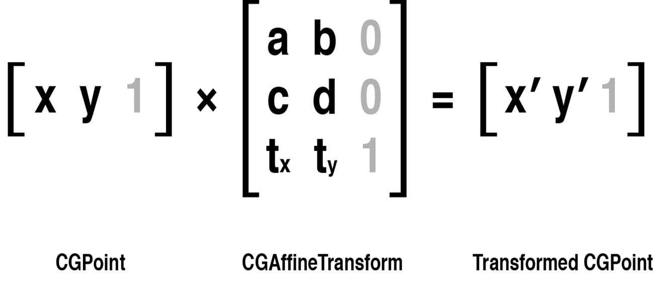
Figure 5.1?CGAffineTransform?and?CGPoint?represented as matrices
?
This multiplication is performed by taking the values in each column of the?CGPoint?vector, multiplying them by the values in each row of the?CGAffineTransform?matrix, then adding the results together to create a new?CGPoint. This explains the additional values shown in gray in the figure; for matrix multiplication to work, the matrix on the left must have the same number of columns as the matrix on the right has rows, so we have to pad out the matrices with so-called?identity?values—numbers that will make the sums work, but without changing the result. We don‘t actually need to store those additional values because they never change, but they are required for the calculation.
为了使得矩阵能够成起来,需要添加一些额外的信息。这些信息都是固定的。上图中灰色的就是。
?
For this reason, you will often see 2D transforms represented as a 3×3 matrix (instead of 2×3). You will also often see the matrix shown in a 3-column-by-2-row format instead, with the vector values stacked vertically. This is known as?column-major?format. The way we‘ve presented it in Figure 5.1 is?row-major?format.
图5.1展示的是row-major 格式的矩阵?
It doesn‘t actually matter which representation you use as long as you are consistent.
?
When the transform matrix is applied to a layer, each corner point of the layer rectangle is individually transformed, resulting in a new quadrilateral shape.
当一个转移矩阵应用到了layer,layer 矩形的每个corner point 都独立转移,导致一个新的四面形
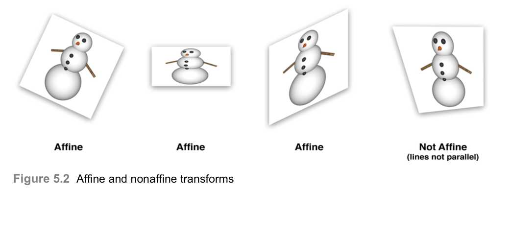
The "affine" in?CGAffineTransform?just means that whatever values are used for the matrix, lines in the layer that were parallel before the transform will remain parallel after the transform. A?CGAffineTransform?can be used to define?any?transform that meets that criterion. Figure 5.2 shows some examples of affine and nonaffine transforms:
affine 的意思就是不论是在转移前后,在layer上的线在转移前是平行的,那么转移后仍然是平行的。
?
?
Creating a?CGAffineTransform ? 创建一个CGAffineTransform?
A full explanation of matrix mathematics is beyond the scope of this book, and if you are not already familiar with matrices, the idea of a transform matrix can seem quite daunting. Fortunately, Core Graphics provides a number of built-in functions for building up arbitrary transforms out of simple ones without requiring the developer to do any math. The following functions each create a new?CGAffineTransform?matrix from scratch:
?
CGAffineTransformMakeRotation(CGFloat?angle)
CGAffineTransformMakeScale(CGFloat?sx,?CGFloat?sy) CGAffineTransformMakeTranslation(CGFloat?tx,?CGFloat?ty)
?
The rotation and scale transforms are fairly self-explanatory—they rotate and scale a vector respectively.
他们分别用来旋转和缩放一个向量
A?translation?transform just adds the specified x and y values to the vector— so if the vector represents a point, it moves the point.
一个translation 仅仅添加指定的x和y到向量上。
Let‘s demonstrate the effect of these functions with a simple project. We‘ll start with an ordinary view and apply a 45-degree rotation transform (see Figure 5.3).
?
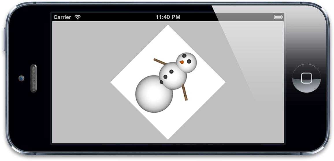
Figure 5.3?A view rotated 45 degrees using an affine transform
?
A?UIView?can be transformed by setting its?transform?property, but as with all layout properties, the?UIView transform?is really just a wrapper around an equivalent?CALayer?feature.
UIView能够通过设置transform属性,但是和别的layout属性相同,UIView transform 仅仅包裹了CALayer的一个相同的属性
?
CALayer?also has a?transform?property, but its type is?CATransform3D, not?CGAffineTransform.
CALayer仍然有一个transform 属性,但是它的类型是CATransform3D,而不是CGAffineTransform
We come back to that later in the chapter, but for now it‘s not what we‘re looking for. The?CALayer?equivalent to the?UIView transform?property is called?affineTransform.
CALayer有一个与UIView 的transform 属性相同的属性叫做affineTransform.?
Listing 5.1 shows the code for rotating a layer by 45 degrees in the clockwise direction using the?affineTransform?property.
?
?
Listing 5.1?Rotating a Layer by 45 Degrees Using?affineTransform
@interface?ViewController ()
?
@property?(nonatomic,?weak)?IBOutlet?UIView?*layerView;
@end
@implementation?ViewController
- (void)viewDidLoad {
[super?viewDidLoad];
//rotate the layer 45 degrees
CGAffineTransform?transform = CGAffineTransformMakeRotation(M_PI_4);
self.layerView.layer.affineTransform = transform;
}
@end
?
Note that the value we‘ve used for the angle is a constant called?M_PI_4, not the number 45 as you might have expected. The transform functions on iOS use radians rather than degrees for all angular units.
这个函数使用的是弧度而不是角度 。
Radians are usually specified using multiples of the mathematical constant??(pi).??radians equates to 180 degrees, so??divided by 4 is equivalent to 45 degrees.
?
The C math library (which is automatically included in every iOS project) conveniently provides constants for common multiples of?, and?M_PI_4?is the constant representing??divided by 4. If you struggle to think in terms of radians, you can use these macros to convert to and from degrees:
?
#define?RADIANS_TO_DEGREES(x) ((x)/M_PI*180.0)
#define?DEGREES_TO_RADIANS(x) ((x)/180.0*M_PI)
Combining Transforms ?组合转移
Core Graphics also provides a second set of functions that can be used to apply a further transform on top of an existing one. This is useful if you want to create a single transform matrix that both scales?and?rotates a layer, for example. These functions are as follows:
CGAffineTransformRotate(CGAffineTransform?t,?CGFloat?angle) CGAffineTransformScale(CGAffineTransform?t,?CGFloat?sx,?CGFloat?sy) CGAffineTransformTranslate(CGAffineTransform?t,?CGFloat?tx,?CGFloat?ty)
When you are manipulating transforms, it is often useful to be able to create a transform that does nothing at all—the?CGAffineTransform?equivalent of zero or nil. In the world of matrices, such a value is known as the?identity matrix, and Core Graphics provides a convenient constant for this:
CGAffineTransformIdentity
?
Finally, if you ever want to combine two existing transform matrices, you can use the following function, which creates a new?CGAffineTransform?matrix from two existing ones:
如果你想结合两个已经存在的transform matrices,你需要使用下面的函数:
CGAffineTransformConcat(CGAffineTransform?t1,?CGAffineTransform?t2);
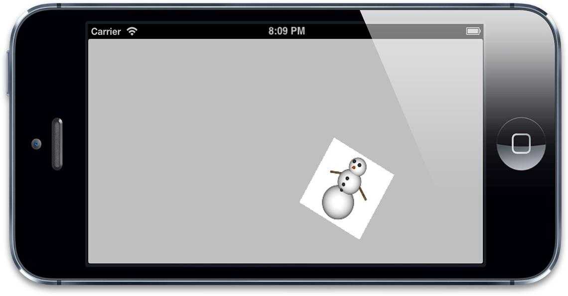
Let‘s use these functions in combination to build up a more complex transform. We‘ll start by applying a scale factor of 50%, then a 30-degree rotation, and finally a translation of 200 points to the right (see Listing 5.2). Figure 5.4 shows the result of applying these transforms to our layer.
Listing 5.2?Creating a Compound Transform Using Several Functions
- (void)viewDidLoad {
?
[super?viewDidLoad];
//create a new transform
?
CGAffineTransform?transform = CGAffineTransformIdentity;
//scale by 50%
transform = CGAffineTransformScale(transform,?0.5,?0.5);
//rotate by 30 degrees
transform =?CGAffineTransformRotate(transform, M_PI /?180.0?*?30.0);
//translate by 200 points
transform = CGAffineTransformTranslate(transform,?200,?0);
//apply transform to layer
?
self.layerView.layer.affineTransform = transform;
}
?
?
Figure 5.4?The effect of multiple affine transforms applied in sequence
There are a few things worth noting about Figure 5.4: The image has been moved to the right, but not as far as we specified (200 points), and it has also moved down instead of just sideways. The reason for this is that when you apply transforms sequentially in this way, the previous transforms affect the subsequent ones. The 200-point translation to the right has been rotated by 30 degrees and scaled by 50%, so it has actually become a translation diagonally downward by 100 points.
?
This means that the order in which you apply transforms affects the result; a translation followed by a rotation is not the same as a rotation followed by a translation.
这也就意味着你应用的transforms 影响到了结果;
?
The Shear Transform?
?
剪切变换[1]??(Shear Transform)——又称"错切变换",是仿射变换的一种原始变换,指的是类似于四边形不稳定性那种性质,方形变平行四边形,任意一边都可以被拉长的过程。
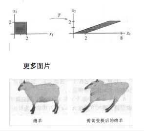
Because Core Graphics provides functions to calculate the correct values for the transform matrix for you, it‘s rare that you need to set the fields of a?CGAffineTransform?directly. One such circumstance is when you want to create a?shear?transform, for which Core Graphics provides no built-in function.
?
The shear transform is a fourth type of affine transform. It is less commonly used than translation, rotation, and scaling (which is probably why Core Graphics has no built-in function for it), but it can still sometimes be useful. Its effect is probably best illustrated with a picture (see Figure 5.5). For want of a better term, it makes the layer "slanty." Listing 5.3 shows the code for the shear transform function.
?
?
Figure 5.5?A horizontal shear transform
Listing 5.3 Implementing a Shear Transform
@implementation?ViewController
CGAffineTransform?CGAffineTransformMakeShear(CGFloat?x,?CGFloat?y) {
?
CGAffineTransform?transform =?CGAffineTransformIdentity;
transform.c?= -x;
transform.b?= y;
return?transform;
}
- (void)viewDidLoad {
[super?viewDidLoad];
//shear the layer at a 45-degree angle
self.layerView.layer.affineTransform?=?CGAffineTransformMakeShear(1,?0);
}
?
@end
?
3D Transforms 3D 转移变换
As the CG prefix indicates, the?CGAffineTransform?type belongs to the Core Graphics framework. Core Graphics is a strictly 2D drawing API, and?CGAffineTransform?is intended only for 2D transforms (that is, ones that apply only within a two-dimensional plane).
?
In Chapter 3, we looked the?zPosition?property, which enables us to move layers toward or away from the camera (the user‘s viewpoint). The?transform?property (which is of type?CATransform3D) generalizes this idea, allowing us to both move?and?rotate a layer in three dimensions.
CALayer的transform属性 可以移动和旋转一个layer在三维空间中
?
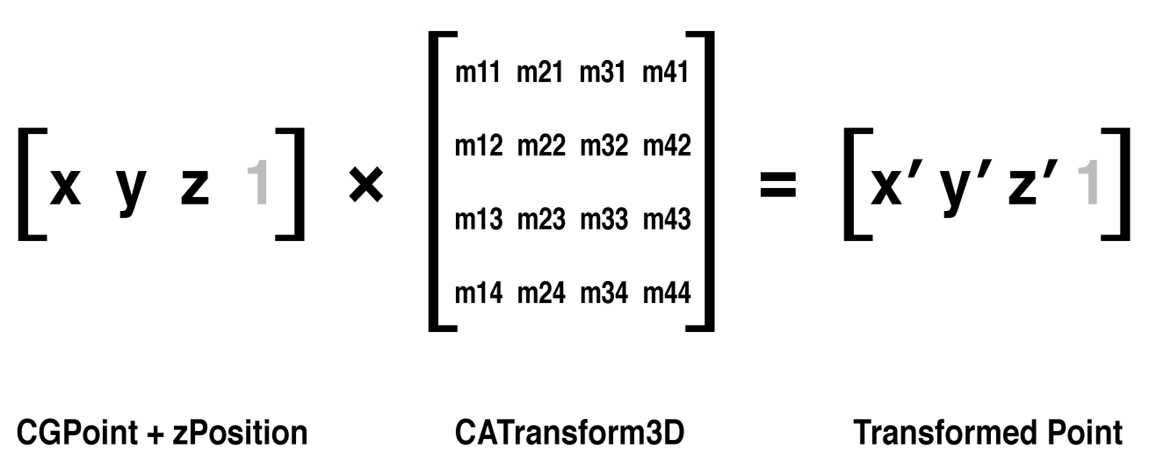
Like?CGAffineTransform,?CATransform3D?is a matrix. But instead of a 2-by-3 matrix,?CATransform3D?is a 4-by-4 matrix that is capable of arbitrarily transforming a point in 3D (see Figure 5.6).
CATransforms3D是一个矩阵,是一个4*4 的矩阵
?
Figure5.6?The?CATransform3D?matrix transforming a 3D point
Core Animation provides a number of functions that can be used to create and combine?CATransform3D?matrices in exactly the same way as with?CGAffineTransform?matrices. The functions are similar to the Core Graphics equivalents, but the 3D translation and scaling functions provide an additional?z?argument, and the rotation function accepts an?x,?y, and?z?argument in addition to the?angle, which together form a vector that defines the axis of rotation:
CATransform3DMakeRotation(CGFloat?angle,?CGFloat?x,?CGFloat?y,?CGFloat?z) CATransform3DMakeScale(CGFloat?sx,?CGFloat?sy,?CGFloat?sz) CATransform3DMakeTranslation(Gloat?tx,?CGFloat?ty,?CGFloat?tz)
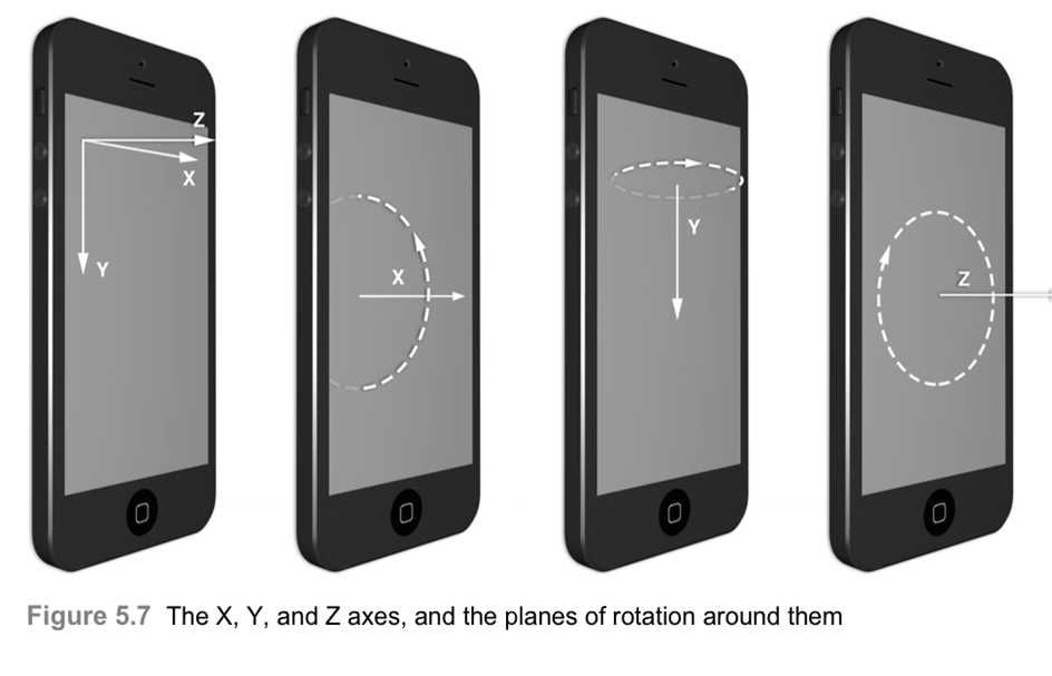
You should now be familiar with the X and Y axes, which extend to the right and down respectively (although you may recall from Chapter 3 that this is only the case on iOS; on Mac OS, the Y axis points upward). The Z axis is perpendicular to those axes and extends outward toward the?camera?(see Figure 5.7).
?
?
As you can see from the figure, a rotation around the Z axis is equivalent to the 2D affine rotation we made earlier. A rotation around the X or Y axes, however, rotates a layer?out?of the 2D plane of the screen and tilts it away from the camera.
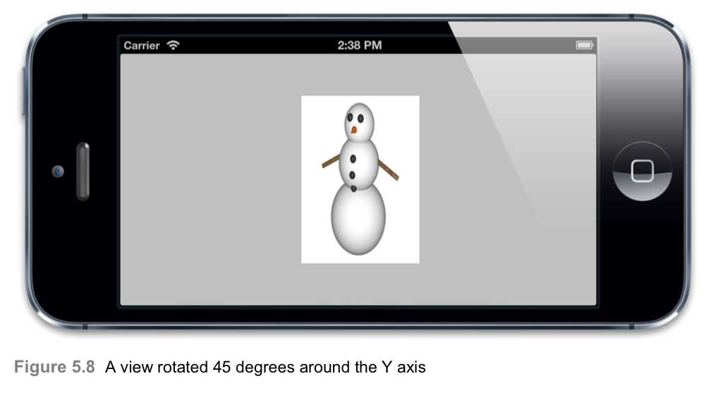
Let‘s try an example: The code in Listing 5.4 uses?CATransform3DMakeRotation?to rotate our view‘s backing layer by 45 degrees around the Y axis. We would expect this to tilt the view to the right, so that we are looking at it from an angle.
The result is shown in Figure 5.8, but it‘s not quite what we would have expected.
Listing 5.4 Rotating a Layer Around the Y Axis
@implementation?ViewController
- (void)viewDidLoad {
[super?viewDidLoad];
//rotate the layer 45 degrees along the Y axis
CATransform3D?transform =?CATransform3DMakeRotation(M_PI_4,?0,?1,?0);
self.layerView.layer.transform?= transform; }
?
@end
?
?
?
It doesn‘t really look like the view has been rotated at all; it looks more like it‘s been
horizontally squashed using a scale transform. Did we do something wrong?
?
No, this is actually correct. The view looks narrower because we are looking at it diagonally, so there is less of it facing the camera. The reason it doesn‘t look right is because there is no?perspective.
看着不好的原因是没用perspective 透视法
Perspective Projection
In real life, when things are farther away, they seem to get smaller due to perspective. We would expect the side of the view that is farther away from us to appear shorter than the side that is closer, but that isn‘t happening. What we are looking at currently is an?isometric projection?of our view, which is a method of 3D drawing that preserves parallel lines, much like the affine transforms we were using earlier.
In an isometric projection, objects that are farther away appear at the same scale as objects that are close to us. This kind of projection has its uses (for example, for an architectural drawing, or a top-down, pseudo-3D videogame), but it‘s not what we want right now.
?
To fix this, we need to modify our transform matrix to include a?perspective transform?(sometimes called the?z transform) in addition to the rotation transform we‘ve already applied.
我们需要修改我们的transform matrix 来包含一个perspective transform ?
Core Animation doesn‘t give us any functions to set up a perspective transform, so we‘ll have to modify our matrix values manually. Fortunately, though, this is simple:
?
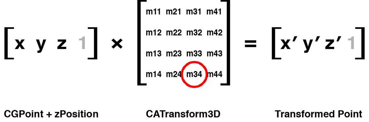
The perspective effect of a?CATransform3D?is controlled by a single value in the matrix: element?m34. The?m34?value (shown in Figure 5.9) is used in the transform calculation to scale the X and Y values in proportion to how far away they are from the camera.
透视效果 由一个简单的矩阵元素控制:m34
?
?
Figure5.9?them?m34?value of?CATransform3D,used for perspective
?
By default,?m34?has a value of zero. We can apply perspective to our scene by setting the?m34?property of our transform to -1.0 /?d, where?d?is the distance between the imaginary camera and the screen, measured in points. How do we calculate what this distance should be? We don‘t have to; we can just?make something up.
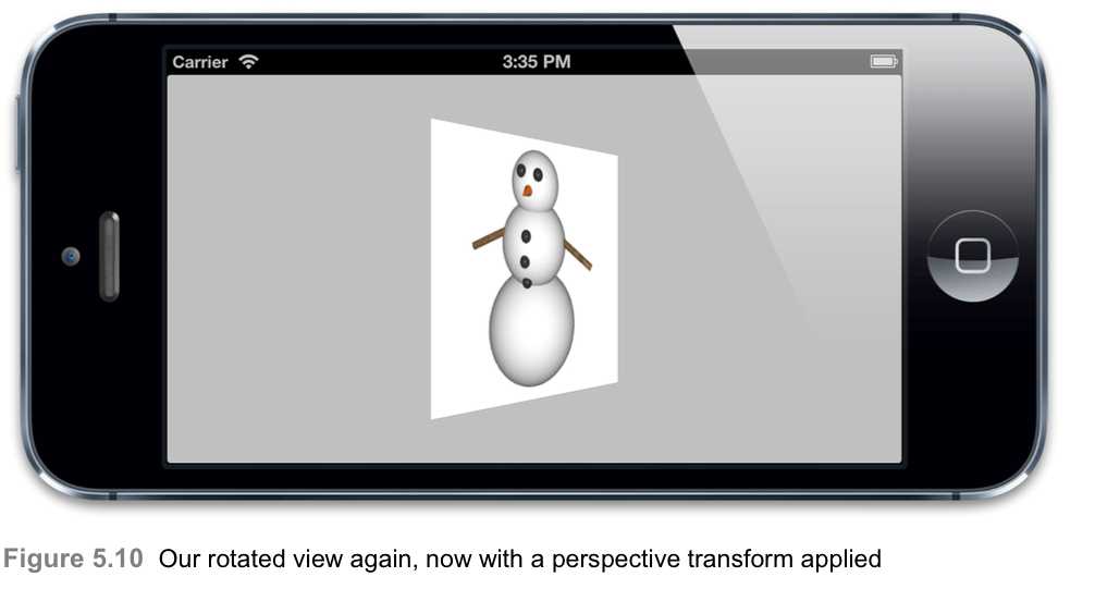
Because the camera doesn‘t really exist, we are free to decide where it is positioned based on what looks good in our scene. A value between 500 and 1000 usually works fairly well, but you may find that smaller or larger values look better for a given layer arrangement. Decreasing the distance value increases the perspective effect, so a very small value will look extremely distorted, and a very large value will just look like there is no perspective at all (isometric). Listing 5.5 shows the code to apply perspective to our view, and Figure 5.10 shows the result.
Listing 5.5 Applying Perspective to the Transform
@implementation?ViewController
- (void)viewDidLoad {
[super?viewDidLoad];?//create a new transform
CATransform3D?transform =?CATransform3DIdentity;?//apply perspective
transform.m34?= -?1.0?/?500.0;?//rotate by 45 degrees along the Y axis
transform =?CATransform3DRotate(transform,?M_PI_4,?0,?1,?0);
//apply to layer
self.layerView.layer.transform?= transform;
}
@end
?
?
The Vanishing Point 消失点
When drawn in perspective, objects get smaller as they move away from the camera. As they move?even farther, they eventually shrink to a point. All distant objects eventually converge on a single?vanishing point.
In real life, the vanishing point is always in the center of your view (see Figure 5.11), and generally, to create a realistic perspective effect in your app, the vanishing point should be in the center of the screen, or at least the center of the view that contains all of your 3D objects.
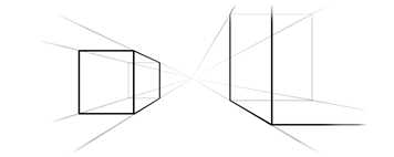
Figure 5.11?The vanishing point
Core Animation defines the vanishing point as being located at the?anchorPoint?of the layer being transformed (which is usually the center of the layer, but may not be—see Chapter 3 for details). That is to say, it‘s located wherever the?anchorPoint?of the view was positioned?prior?to applying the transform; if the transform includes a translation component that moves the layer to somewhere else onscreen, the vanishing point will be wherever it was located before it was transformed.
When you change the?position?of a layer, you also change its vanishing point. This is important to remember when you are working in 3D. If you intend to adjust the?m34?property of a layer to make it appear three-dimensional, you should position it in the center of the screen and then move it to its final location using a translation (instead of changing its?position) so that it shares a common vanishing point with any other 3D layers on the screen.
The?sublayerTransform?Property
If you have multiple views or layers, each with 3D transforms, it is necessary to apply the same?m34?value to each individually and to ensure that they all share a common?position?in the center of the screen prior to being transformed. This is relatively straightforward if you define a constant or function to create and position them all for you, but it is still restrictive (for example, it prevents you from arranging your views in Interface Builder). There is a better way.
?
CALayer?has another transform property called?sublayerTransform.
CALayer 有另外一个transform?属性叫做sublayerTransform
This is also a?CATransform3D, but instead of transforming the layer to which it is applied, it affects only the sublayers.
但是仅仅转移layer ,它仅仅影响sublayers ?
This means you can apply a perspective transform once and for all to a single container layer, and the sublayers will all inherit that perspective automatically.
?
Only having to set the perspective transform in one place is convenient in itself, but it also carries another significant benefit: The vanishing point is set as the center of the?container layer,?not set individually for each sublayer.
消失点 设在container layer的中心,而不是设置在每个sublayer单独的。
This means that you are free to position the sublayers using their?position?or?frame?instead of having to set them all to the center of the screen and move them with transforms to keep their vanishing point consistent.
?
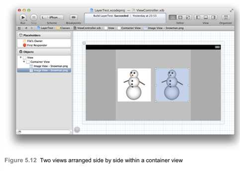
Let‘s demonstrate this with an example. We‘ll place two views side by side in Interface Builder (see Figure 5.12). Now by setting the perspective transform on their containing view, we can apply the same perspective and vanishing point to both of them. See Listing 5.6 for the code and Figure 5.13 for the result.
?
Listing 5.6 Applying a?sublayerTransform?@interface?ViewController ()
?
@property?(nonatomic,?weak)?IBOutlet?UIView?*containerView;
@property?(nonatomic,?weak)?IBOutlet?UIView?*layerView1;
@property?(nonatomic,?weak)?IBOutlet?UIView?*layerView2;
@end
@implementation?ViewController
- (void)viewDidLoad {
[super?viewDidLoad];
//apply perspective transform to container
?
CATransform3D?perspective =?CATransform3DIdentity;
perspective.m34?= -?1.0?/?500.0;
self.containerView.layer.sublayerTransform?= perspective;
//rotate layerView1 by 45 degrees along the Y axis
CATransform3D?transform1 =?CATransform3DMakeRotation(M_PI_4,?0,?1,?0);?self.layerView1.layer.transform?= transform1;
//rotate layerView2 by 45 degrees along the Y axis
CATransform3D?transform2 =?CATransform3DMakeRotation(-M_PI_4,?0,?1,?0);
self.layerView2.layer.transform?= transform2; }
?
@end
?

?
?
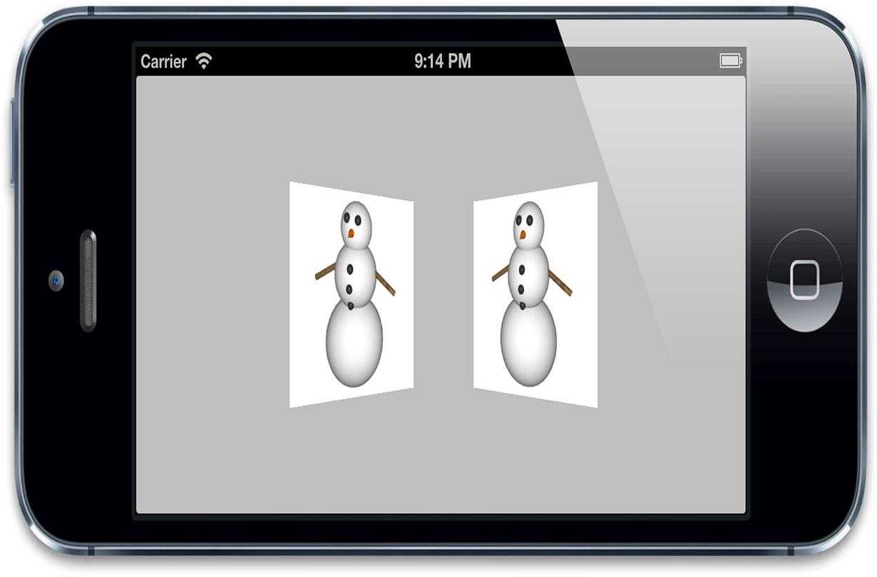
Figure 5.13?Two individually transformed views with shared perspective
?
Backfaces
Now that we can rotate our layers in 3D, we can look at them?from behind.?If we change the angle in Listing 5.4 to?M_PI?(180 degrees) rather than?M_PI_4?(45 degrees) as it is currently, we will have rotated the view a full half-circle, such that it is facing directly away from the camera.
?
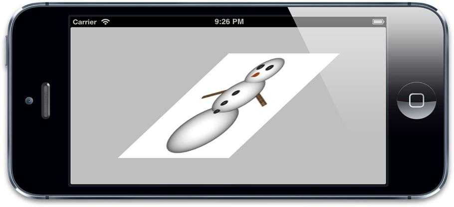
What does a layer look like from the back? See Figure 5.14 to find out.
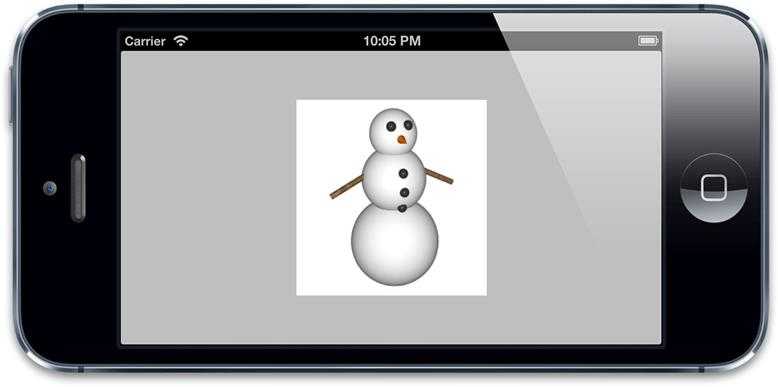
Figure 5.14?The rear side of our view, showing a mirrored snowman image
As you can see, layers are double-sided; the reverse side shows a mirror image of the front.
This isn‘t necessarily a desirable feature, though. If your layer contains text or controls, it‘s going to be very confusing if the user sees the mirror image of these. It‘s also potentially wasteful: Imagine a solid object such as an opaque cube formed from layers—why waste GPU cycles drawing the layers on the reverse side of the cube if we can never see them?
?
CALayer?has a property called?doubleSided?that controls whether the reverse side of a layer should be drawn. The?doubleSided?property is a?BOOL?and defaults to?YES. If you set it to?NO, then when the layer is facing away from the camera, it will not be drawn at all.
CALayer有一个属性叫做doubleSided 控制是否允许反转layer 应该被绘制。
Layer Flattening
?
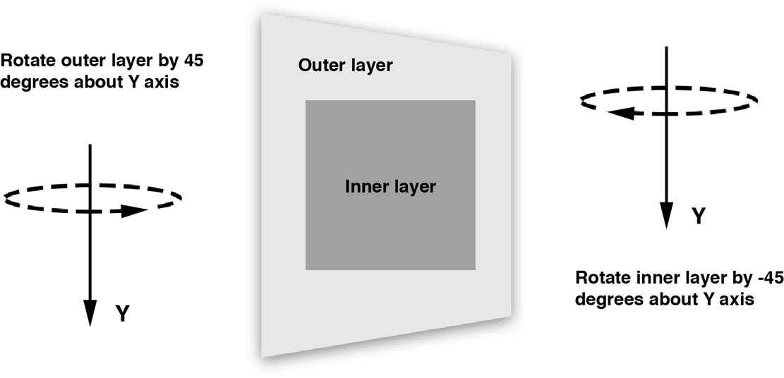
What happens if we transform a layer containing another layer that has itself been transformed in the opposite direction? Confused? See Figure 5.15.
?
?
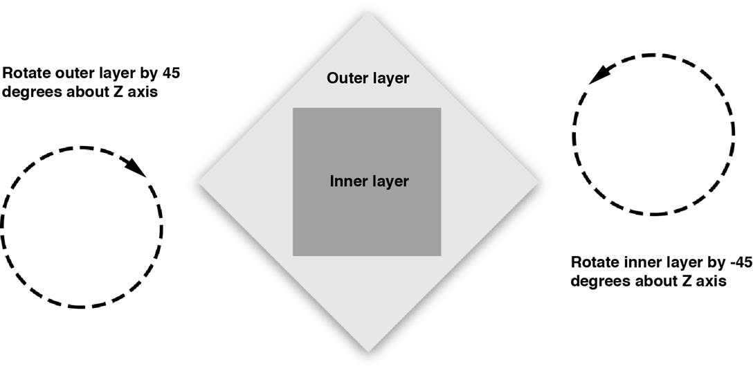
Figure 5.15?Nested layers with opposite transforms applied
Note how the negative 45-degree rotation of the inner layer cancels out the 45-degree
rotation of outer layer so that the inner layer is pointing the right way up.
Logically, if an inner layer has the opposite transform to its outer layer (in this case, a rotation about the Z axis), then we would expect the two transforms to cancel each other out.
Let‘s verify that this is the case in practice. Listing 5.7 shows the code to do this, and Figure 5.16 shows the result.
?
Listing 5.7?Opposite Rotation Transforms Around Z Axis
、@interface?ViewController ()
?
@property?(nonatomic,?weak)?IBOutlet?UIView?*outerView;
@property?(nonatomic,?weak)?IBOutlet?UIView?*innerView;
@end
@implementation?ViewController
- (void)viewDidLoad {
[super?viewDidLoad];
//rotate the outer layer 45 degrees
CATransform3D?outer =?CATransform3DMakeRotation(M_PI_4,?0,?0,?1);
self.outerView.layer.transform?= outer;
//rotate the inner layer -45 degrees
CATransform3D?inner =?CATransform3DMakeRotation(-M_PI_4,?0,?0,?1);
self.innerView.layer.transform?= inner;
}
@end
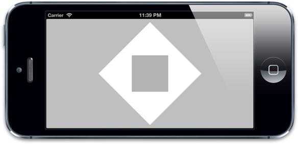
Figure 5.16?The rotated views match the predicted behavior in Figure 5.15.
That seems to have worked as expected. Now let‘s try it in 3D. We‘ll modify our code to rotate the inner and outer views along the Y axis instead of the Z axis, and also add perspective so we can see more clearly what‘s going on. We can‘t use the?sublayerTransform?trick from Listing 5.6 because our inner layer is not a direct sublayer of the container, so we‘ll just apply the perspective transform separately to each layer (see Listing 5.8).
Listing 5.8 Opposite Rotation Transforms Around Y Axis
- (void)viewDidLoad {
[super?viewDidLoad];
//rotate the outer layer 45 degrees
?
CATransform3D?outer =?CATransform3DIdentity;
outer.m34?= -1.0?/?500.0;
outer =?CATransform3DRotate(outer,?M_PI_4,?0,?1,?0);
self.outerView.layer.transform?= outer;
//rotate the inner layer -45 degrees
?
CATransform3D?inner =?CATransform3DIdentity;
inner.m34?= -1.0?/?500.0;
inner =?CATransform3DRotate(inner,-M_PI_4,0,1,0);
self.innerView.layer.transform?= inner;
}
We should expect to see something like Figure 5.17.
Figure 5.17?Expected result of opposite rotations around the Y axis
But that‘s not what we see. Instead, what we see looks like Figure 5.18. What‘s happened? Our inner layer is still noticeably tilted to the left, and it‘s also distorted; it was supposed to be face-on and square!
?
It turns out that although Core Animation layers exist in 3D space, they don‘t all exist in?the same?3D space. The 3D scene within each layer is flattened. When you look at a layer from face on, you see the?illusion?of a 3D scene created by its sublayers, but as you tilt the layer away, you realize that 3D scene is just painted on the layer surface.
?
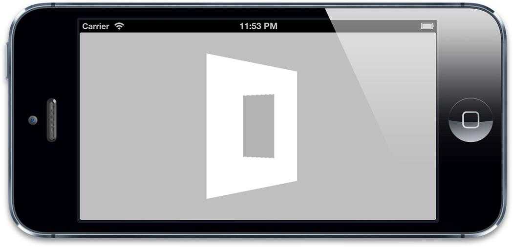
Figure 5.18?Actual result of opposite rotations around the Y axis
To draw an analogy, it‘s just like tilting the screen away when you are playing a 3D game. You might see a wall in front of you in the game, but tilting the screen won‘t allow you to peer around the wall. The scene displayed on the screen doesn‘t change depending on the angle at which you look at it; neither do the contents of a layer.
?
This makes it difficult to create very complex 3D scenes using Core Animation. You cannot use the layer tree to build a hierarchical 3D structure—any 3D surfaces in the same scene must be siblings within the same layer because each parent flattens its children.
At least, that‘s true if you use regular?CALayer?instances. There is a?CALayer?subclass called?CATransformLayer?designed to deal with this problem. This is covered in Chapter 6, "Specialized Layers."
Solid Objects
Now that you understand the basics of positioning layers in 3D space, let‘s try constructing a solid 3D object (well, technically a?hollow?object, but it will?appear?solid). We‘ll create a cube by using six separate views to construct the faces.
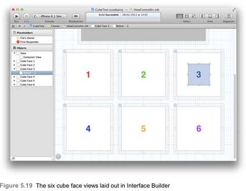
For the purposes of our example, the cube faces are arranged in Interface Builder (see Figure 5.19). We could create the faces in code, but the advantage of using Interface Builder is that we can easily add and arrange subviews within each face. Remember that these faces are ordinary user interface elements that can contain other views and controls. They are fully fledged, interactive parts of our interface, and will remain so even after we fold them up into a cube.
?
The face views are not placed inside the main view but have been arranged loosely in the root of the nib file. We don‘t care about setting the location of these views within their container as we are going to position them programmatically using the layer?transform, and it‘s useful to place them outside of the container view in Interface Builder so that we can easily see their contents. If they all were crammed on top of one another inside the main view, this would be awkward.
We‘ve placed a colored?UILabel?inside each of the views so we can easily identify which is which. Note also the?UIButton?placed in the third face view; this is explained shortly.
Listing 5.9 shows the code to arrange the views in a cube, and Figure 5.20 shows the result.
Listing 5.9 Creating a Cube
@interface?ViewController ()
@property?(nonatomic,?weak)?IBOutlet?UIView?*containerView;
@property?(nonatomic,?strong)?IBOutletCollection(UIView)?NSArray?*faces;
@end
@implementation?ViewController
- (void)addFace:(NSInteger)index withTransform:(CATransform3D)transform {
//get the face view and add it to the container
?
UIView?*face =?self.faces[index];
[self.containerView?addSubview:face];
//center the face view within the container
?
CGSize?containerSize =?self.containerView.bounds.size;
face.center?=?CGPointMake(containerSize.width?/?2.0,
?
containerSize.height?/?2.0);
face.layer.transform?= transform;
}
- (void)viewDidLoad {
[super?viewDidLoad];
//set up the container sublayer transform
?
CATransform3D?perspective =?CATransform3DIdentity;
perspective.m34?= -1.0?/?500.0;
self.containerView.layer.sublayerTransform?= perspective;
//add cube face 1
?
CATransform3D?transform =?CATransform3DMakeTranslation(0,?0,?100);
[self?addFace:0?withTransform:transform];
//add cube face 2
?
transform =?CATransform3DMakeTranslation(100,?0,?0);
transform =?CATransform3DRotate(transform,?M_PI_2,?0,?1,?0);
[self?addFace:1?withTransform:transform];
//add cube face 3
transform =?CATransform3DMakeTranslation(0, -100,?0); transform =?CATransform3DRotate(transform,?M_PI_2,?1,?0,?0); [self?addFace:2?withTransform:transform];
//add cube face 4
transform =?CATransform3DMakeTranslation(0,?100,?0); transform =?CATransform3DRotate(transform, -M_PI_2,?1,?0,?0); [self?addFace:3?withTransform:transform];
//apply the transform
//add cube face 5
transform =?CATransform3DMakeTranslation(-100,?0,?0); transform =?CATransform3DRotate(transform, -M_PI_2,?0,?1,?0); [self?addFace:4?withTransform:transform];
//add cube face 6
?
transform =?CATransform3DMakeTranslation(0,?0, -100);
transform =?CATransform3DRotate(transform,?M_PI,?0,?1,?0);
[self?addFace:5?withTransform:transform];
}
@end
Figure 5.20?The cube, displayed face-on
Our cube isn‘t really that impressive from this angle; it just looks like a square. To
appreciate it properly, we need to look at it from a?different point of view.
Rotating the cube itself would be cumbersome because we‘d have to rotate each face individually. A simpler option is to rotate the?camera, which we can do by adjusting the?sublayerTransform?of our container view.
Add the following lines to rotate the?perspective?transform matrix before applying it to the?containerView?layer:
?
perspective =?CATransform3DRotate(perspective, -M_PI_4,?1,?0,?0);
perspective =?CATransform3DRotate(perspective, -M_PI_4,?0,?1,?0);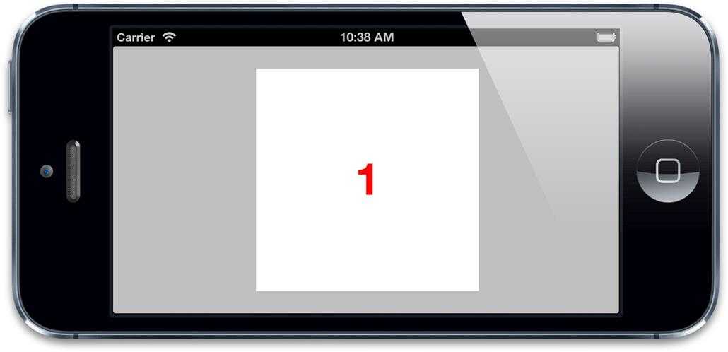
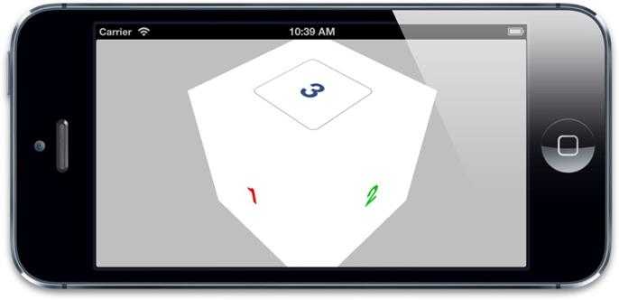
That has the effect of rotating the camera (or rotating the entire scene relative to the camera, depending on how you look at it) 45 degrees around the Y axis, and then a further 45 degrees around the X axis. We are now viewing the cube corner-on and can see it for what it really is (see Figure 5.21).
Figure 5.21?The cube, displayed corner-on
Light and Shadow
It definitely looks more like a cube now, but it‘s difficult to make out the joins between the faces. Core Animation can display layers in 3D, but it has no concept of?lighting.?If you want to make your cube look more realistic, you‘ll have to apply your own shading effects. You can do this by adjusting the different view background colors or by using images with lighting effects pre-applied to them.
If you need to create?dynamic?lighting effects, you can do so by overlaying each view with a translucent black shadow layer with varying alpha based on the view orientation. To calculate the opacity of the shadow layer, you need to get the?normal vector?for each face (a vector that points perpendicular to the surface) and then calculate the?cross product?between that vector and the vector from an imaginary light source. The cross product gives you the angle between the light source and the layer, which indicates the extent to which it should be illuminated.
An implementation of this idea is shown in Listing 5.10. We‘ve used the GLKit framework to do the vector calculations (you‘ll need to include this framework in your project to run the code). The?CATransform3D?for each face is cast to a?GLKMatrix4?using some pointer trickery, and then the 3×3?rotation matrix?is extracted using the
GLKMatrix4GetMatrix3?function. The rotation matrix is the part of the transform that specifies the layer‘s orientation, and we can use it to calculate the normal vector.
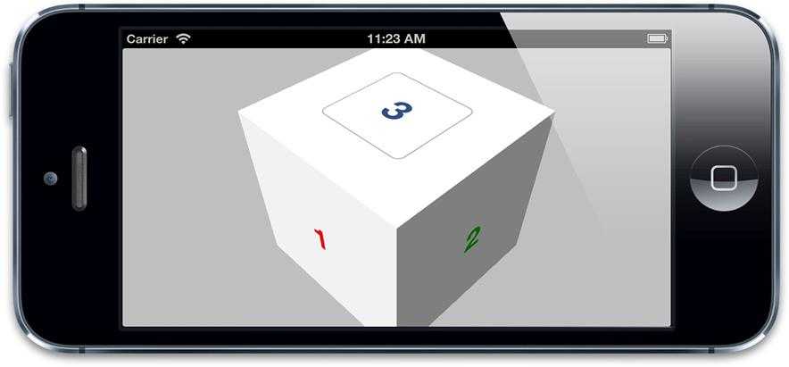
Figure 5.22 shows the result. Try tweaking the?LIGHT_DIRECTION?vector and?AMBIENT_LIGHT?value to alter the lighting effect.
Listing 5.10?Applying Dynamic Lighting Effects to the Cube Faces
#import?"ViewController.h"?#import?<QuartzCore/QuartzCore.h>?#import?<GLKit/GLKit.h>
#define LIGHT_DIRECTION?0,?1, -0.5?#define AMBIENT_LIGHT?0.5
@interface?ViewController?()
@property?(nonatomic,?weak)?IBOutlet?UIView?*containerView;
@property?(nonatomic,?strong)?IBOutletCollection(UIView)?NSArray?*faces;?@end
@implementation?ViewController
- (void)applyLightingToFace:(CALayer?*)face {
//add lighting layer
CALayer?*layer = [CALayer?layer]; layer.frame?= face.bounds;
[face?addSublayer:layer];
//convert the face transform to matrix
//(GLKMatrix4 has the same structure as CATransform3D)?CATransform3D?transform = face.transform;
GLKMatrix4?matrix4 = *(GLKMatrix4?*)&transform;?GLKMatrix3?matrix3 =?GLKMatrix4GetMatrix3(matrix4);
//get face normal
GLKVector3?normal =?GLKVector3Make(0,?0,?1);
normal =?GLKMatrix3MultiplyVector3(matrix3, normal); normal =?GLKVector3Normalize(normal);
//get dot product with light direction
GLKVector3?light =?GLKVector3Normalize(GLKVector3Make(LIGHT_DIRECTION));?float?dotProduct =?GLKVector3DotProduct(light, normal);
//set lighting layer opacity
CGFloat?shadow =?1?+ dotProduct -?AMBIENT_LIGHT;
UIColor?*color = [UIColor?colorWithWhite:0?alpha:shadow]; layer.backgroundColor?= color.CGColor;
}
- (void)addFace:(NSInteger)index withTransform:(CATransform3D)transform {
//get the face view and add it to the container
UIView?*face =?self.faces[index]; [self.containerView?addSubview:face];
//center the face view within the container
CGSize?containerSize =?self.containerView.bounds.size; face.center?=?CGPointMake(containerSize.width?/?2.0,
containerSize.height?/?2.0); face.layer.transform?= transform;
//apply lighting
[self?applyLightingToFace:face.layer]; }
- (void)viewDidLoad {
[super?viewDidLoad];
//set up the container sublayer transform
CATransform3D?perspective =?CATransform3DIdentity; perspective.m34?= -1.0?/?500.0;
perspective =?CATransform3DRotate(perspective, -M_PI_4,?1,?0,?0); perspective =?CATransform3DRotate(perspective, -M_PI_4,?0,?1,?0);?self.containerView.layer.sublayerTransform?= perspective;
//add cube face 1
CATransform3D?transform =?CATransform3DMakeTranslation(0,?0,?100); [self?addFace:0?withTransform:transform];
//add cube face 2
transform =?CATransform3DMakeTranslation(100,?0,?0); transform =?CATransform3DRotate(transform,?M_PI_2,?0,?1,?0); [self?addFace:1?withTransform:transform];
//add cube face 3
transform =?CATransform3DMakeTranslation(0, -100,?0);
//apply the transform
transform =?CATransform3DRotate(transform,?M_PI_2,?1,?0,?0); [self?addFace:2?withTransform:transform];
//add cube face 4
transform =?CATransform3DMakeTranslation(0,?100,?0); transform =?CATransform3DRotate(transform, -M_PI_2,?1,?0,?0); [self?addFace:3?withTransform:transform];
//add cube face 5
transform =?CATransform3DMakeTranslation(-100,?0,?0); transform =?CATransform3DRotate(transform, -M_PI_2,?0,?1,?0); [self?addFace:4?withTransform:transform];
//add cube face 6
transform =?CATransform3DMakeTranslation(0,?0, -100); transform =?CATransform3DRotate(transform,?M_PI,?0,?1,?0); [self?addFace:5?withTransform:transform];
}
?
@end
?
Figure 5.22?The cube, now with dynamically calculated lighting
Touch Events
You may have also noticed that we can now see the button on the third face. If you press it, nothing happens. Why is that?
It‘s not because iOS cannot correctly transform the touch events to match the button position in 3D; it‘s actually quite capable of doing that. The problem is the?view order.?As we mentioned briefly in Chapter 3, touch events are processed according to the order of views within their superview, not their Z-position in 3D space. When we added our cube face views, we added them in numeric order, so faces 4, 5, and 6 are in front of face 3 in the view/layer order.
Even though we can‘t see faces 4, 5, and 6 (because they are obscured by faces 1, 2, and 3), iOS still gives them first dibs on touch events. When we try to tap the button on face 3, face 5 or 6 (depending on where we tap) is intercepting the touch event, just as it would if we had placed it in front of the button in a normal 2D layout.
You might think that setting?doubleSided?to?NO?might help here, as it would render the rearward facing views invisible, but unfortunately that doesn‘t help; views that are hidden because they are facing away from the camera will still intercept touch events (unlike views that are hidden using the?hidden?property, or by setting their?alpha?to zero, which don‘t), so disabling double-sided rendering won‘t help with this issue (although it might be worth doing anyway for performance reasons).
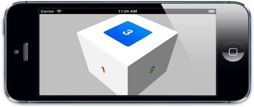
There are a couple of solutions to this: We could set?userInteractionEnabled?to?NO?on all of our cube face views except face 3 so that they don‘t receive touches. Or we could simply add face number 3 to the view hierarchy?after?face number 6 in our program. Either way, we will then be able to press the button (see Figure 5.23).
Figure 5.23?Now the background views aren‘t blocking the button, we can press it.
Summary
?
This chapter covered 2D and 3D transforms. You learned a bit about matrix math, and how to create 3D scenes with Core Animation. You saw what the back of a layer looks like and learned that you can‘t peer around objects in a flat image. Finally, this chapter demonstrated that when it comes to handling touch events, the order of views or layers in the hierarchy is more significant than their apparent order onscreen.
?
Chapter 6 takes a look at the specialized?CALayer?subclasses provided by Core Animation and their various capabilities.
标签:
原文地址:http://www.cnblogs.com/ljlkfx/p/4789613.html