标签:
The underground waste containers in my neighborhood used to have an access system based on Texas Instruments’ TIRIS RFID tags.
The tags contain a 64-bit read-only identifier that is read using a low-frequency (LF) electromagnetic field of around 134 kHz.
Data bits are modulated using Frequency Shift Keying (FSK).
Since the system was fairly simple and involved signals of relatively low frequencies,
I decided to have a go at creating a microcontroller based solution to emulate and read these RFID tags.
The main problem would be the design of the analog front-end.
A tuned coil, driven at the correct frequencies, was needed to emulate an authentic tag and to be able to read other tags.
An amplification and filtering stage was required to receive the often small return-signals of the tags.
Signal modulation and demodulation would be done entirely using the PIC microcontroller.
The software was coded using assembly to have better control of the strict signal timings.
The initial analog front-end was based on a pair of bipolar transistors to drive the coil.
A diode clamping section was needed to prevent the signal levels from getting too high for the microcontroller input.
This design didn’t work that well in practice because of the lack of amplification.
It could emulate tags but wasn’t able to read them and it also needed a more elaborate transistor biasing circuit.
Searching for better solutions, I found an Elektor article (TIRIS RFID Reader – October 2005),
describing an analog interface containing an amplification stage using op-amps (NE5532)
and a driving section using P- and N-channel MOSFETs.
I based my design for the most part on the design from this article with only minor changes to the components used.
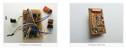
The images below show the prototype of this improved design on breadboard,
with the microcontroller on the bottom and the analog front-end on a separate PCB on top, to reduce unwanted noise.
The prototyping PCB in the top-right corner, shown in detail in the right image, contains the SMD read-coil and tuning capacitors.

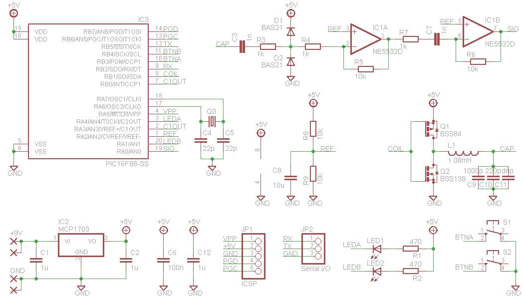
After the prototype on breadboard was working, I started designing the final hardware. The goal was to make the emulator portable, so I could easily use it outdoors. I decided to use a 9V battery to power it because it has enough capacity and it’s simple to convert to 5V using a linear regulator. The following schematic shows the completed design, including microcontroller, analog front-end, user-interface and power supply.

Coil L1 measures 1.08 mH and resonates at the correct frequency with the addition of 1220 pF of tuning capacitance (C9-C11). The coil is driven by two SMD FETs (Q1 and Q2) and delivers its signal (CAP) via a diode clamping stage (D1 and D2), to the dual op-amps of IC1. The diodes also bias the signal to around half the supply voltage (~2.5V). A reference voltage for the op-amps and the microcontroller is generated using 10 kΩ resistors R8 and R9 and 10 µF capacitor C8. The output signal of IC1 (SIG) is connected to the comparator input of the PIC.
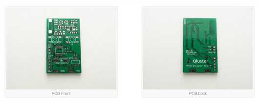
The corresponding PCBs measure 29.5 x 50 mm and were designed to use mostly SMD components.

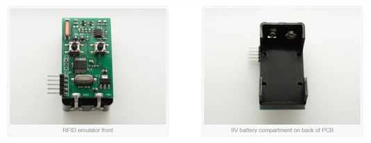
The populated PCB is shown below. It is mounted on a Keystone 1294 9V battery holder with slightly bent solder tabs. The coil at the top-left is a Coilcraft 4308RV series 1.08 mH RFID transponder coil (4308RV-115X). This SMD coil has a slightly reduced operating range compared to a full-size coil, but is far more portable and works almost as well. The two buttons can be controlled with one hand and the LEDs give feedback on the current operating state. The PCB also features connectors for serial communications and in-circuit reprogramming of the microcontroller.

Schematic and PCB layout are available in the downloads section.
Transmitting tag data is accomplished by switching the coil output according to precisely timed bit-sequences. Delays are generated by jumping into a delay-table at specific locations. Every instruction used has a specific delay, so a lot of care has to be taken to output a correctly timed signal. For receiving, the internal comparator is wired to the CCP module in such a way that an interrupt is triggered on a rising edge of the input signal. This allows the software to measure the frequency of the input signal using a timer, and determine the value of the bits received.
标签:
原文地址:http://www.cnblogs.com/shangdawei/p/4827812.html