标签:
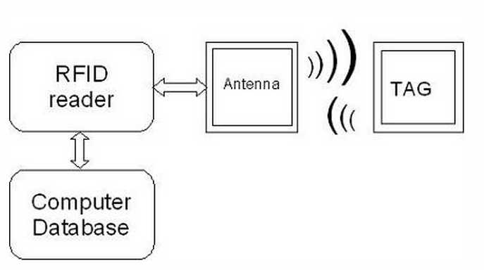
RFID is so called Radio Frequency Identification system which consists of two main parts:
transmitter and receiver. The labels, access cards and even passports in some countries they have RFID transponders integrated.
There can be three types of RFID transponders: Passive, Active and semi-passive.
Transponders (tags) of passive RFID system don’t have power supply.
This is why they are called passive.
Passive tags are powered from electromagnetic field generated by reader antenna.
Reader antenna has to transmit enough power to provide enough energy to tag so it could to transmit back data.
Because of this reading distance is very limited – up to several centimeters.
Well some of implementations may reach several meters.
Passive tags are most common used because they are cheap,
can last indefinitely long as there is no need for power supply,
and they are small size what allows them easy to integrate almost
in every environment starting wrists, necklaces, cards, stickers.
Passive tags simply consist of single IC and antena coil which is usually flat.
Passive tags are operating below 100MHz frequencies
(most common frequencies are 125kHz – 134.2kHz and 13.56MHz)
and main transfer energy is carried by magnetic field.
Magnetic field generated voltage in the coil which is used as power supply also as data signal.
There are also HF passive tags that operate at 900MHz and 2.45GHz.
These tags have dipole antena (1/8 wave length)construction.
With these tags distance may reach more than 3 meters.
But high frequency tags require more expensive manufacturing processing with more precise electronics,
but they can support up to 2Mb/s data stream.
Active RFID tags may provide all advantages of RFID system because tags are fully powered transmitters.
They don’t have to be activated by antenna reader.
Active RFID topic may be very wide because there are many areas where an how they can be used.
In some cases tags may not need a reader antena because tags in some particular cases can be configured to interact with each other.
Active transponders can communicate in very long ranges up to several hundred kilometers.
Main disadvantages of active tags may be relatively big size and production price compared to passive ones.
Semi-Passive tags are more similar to passive transponders than active.
These tags are powered from battery or so called battery assisted tags,
but radio transmission depends on antena activity.
As data processor had it own power, so all received power can be used for transmitting back the signal
which is stronger than passive transducer.
This allows to increase communication distance with quit cheap solution.
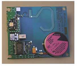
Semi passive RFID tags augment the energy from reader antenna,
but they are not constantly beaming signals as active tags does.
Semi-passive RFID tags use a process to generate a tag response similar to that of passive tags.
Semi-passive tags differ from passive in that semi passive tags possess an internal battery
for the tag’s circuitry which allows the tag to complete other functions such as monitoring
of environmental conditions (temperature, shock) and which may extend the tag signal range.
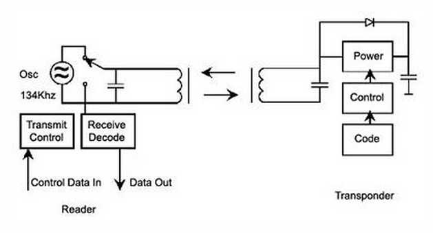
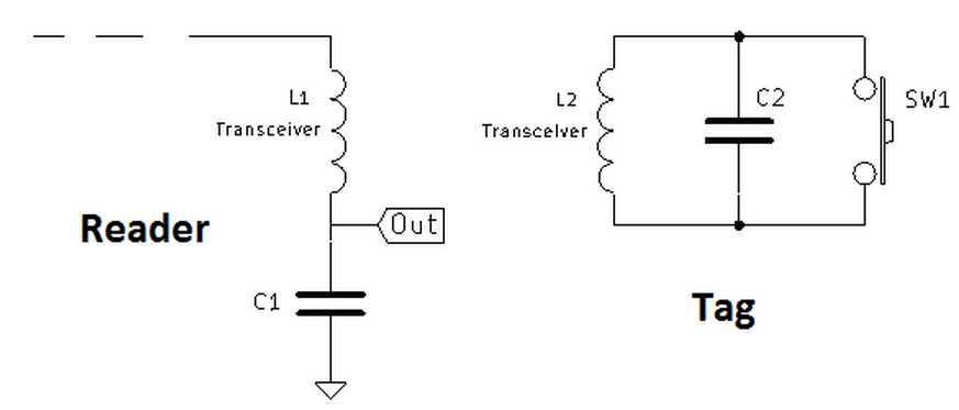
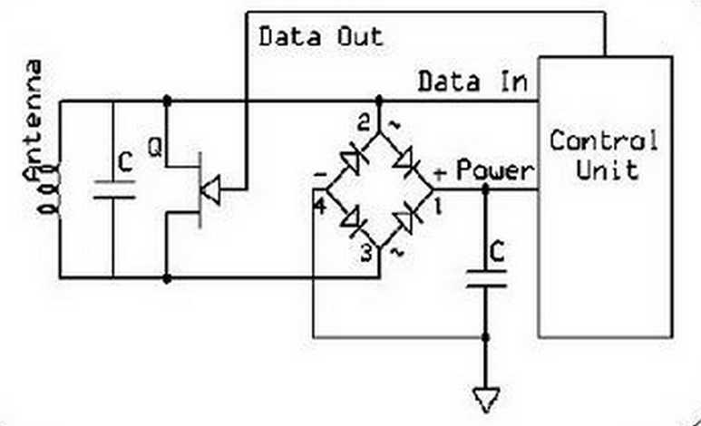

Lets take an example of passive transponder data transmission which sends out data at frequency of 134.2kHz.
Reader or so called interrogator sends out 134.2kHz pulse which lasts for 50ms which is used
to power passive tag and start up the transponder controller.
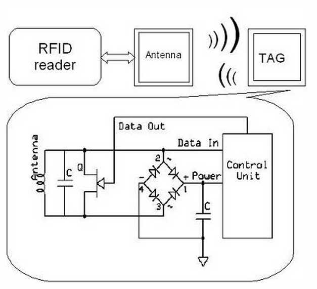
Received energy is stored in cap pacitor inside transponder.
After this 50ms pulse ends, transponder transmits data back over period 20ms.
After tag transmitting is over, capacitor discharges and resets for next readings.
Passive Tag transmission is usually performed by switching low resistance across the antenna coil.
The change of voltage across antenna generates radio frequency which is referred as backscattering.
Data is read from tags ROM memory and transmitted serially by switching coil load switch.
Coil switch is driven by carrier clock source which is modulated with data from serial ROM memory data.
In other end the reader removes(demodulates) the carrier signal, filters and cleans up the signal with Schmitt trigger.
Then signal enters digital section, where CRC code is checked and decoded.
Published on: 21 May 2013
Designed by: Vassilis Serasidis on 18 August 2012
Updated on: 12 June 2014 by Vassilis Serasidis.
Programming language: C
IDE: AVRstudio 6
Target MCU: ATtiny13 (internal 9.6 MHz oscillator
ATtiny85 (internal 8 MHz oscillator).
Tag frequency:125 kHz
Power supply voltage: +5V DC.
Output data:Serial 9600 bps 8N1. It outputs the 10-digit Tag serial number.
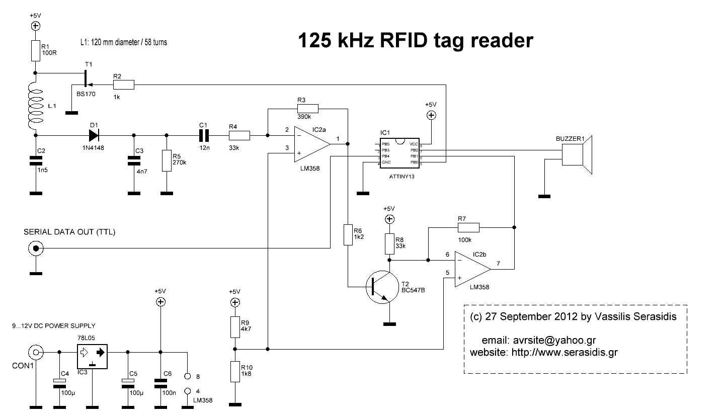
RFID Reader Writer Detector Emulator Sniffer
标签:
原文地址:http://www.cnblogs.com/shangdawei/p/4830485.html