标签:
对于MSP430G2553,硬件I2C由外设USCI(Universal Serial Communication Interface)提供。USCI又分为USCI_A和USCI_B,其中USCI_A支持UART/IrDA/LIN/SPI通讯,USCI_B支持I2C/SPI通讯。MSP430G2553带有一个USCI_A和一个USCI_B,硬件I2C对应的管脚为P1.6(UCB0SCL)和P1.7(UCB0SDA)。
由于Launchpad上P1.6连接到了LED2,因此在使用硬件I2C时,务必要将LED2对应的跳线取下,否则总线无法正常工作。
在官方MSP430x2xx Family User‘s Guide中,已对USCI_B的I2C模式进行的详细的介绍。了解这些信息,由于排查I2C通讯中可能遇到的问题。然而,本着不重复发明轮子的想法,TI已经提供了详细的I2C驱动代码和使用范例,正常开发只要增加TI的代码文件并稍作更改,直接调用TI提供的函数即可。
几个可参考的官方USCI I2C驱动资料/范例有:
Application Report, Using the USCI I2C Master, SLAA382A
—— 重点推荐。
Application Report, Using the USCI I2C Slave, SLAA383
—— 重点推荐。
—— 包含了CRC的计算方法,驱动代码增加了对I2C器件响应超时异常的判断。
Application Report, Using the MSP430 Launchpad as a Standalone I2C Host for Audio Products, SLAA605A
—— 除了USCI I2C,还包含了GPIO I2C的驱动代码。
Application Report, Interfacing an EEPROM via I2C Using the MSP430, SLAA208A
—— 驱动封装了操作EEPROM的I2C函数。
I2C驱动使用SLAA382A提供的USCI I2C Master Library(without DMA support),将其中的TI_USCI_I2C_master.c代码device specific header修改#include相关头文件为:
#include "io430.h"
(IAR的project option中已选择器件为G2553)
在TI_USCI_I2C_receiveinit()和TI_USCI_I2C_transmitinit()函数中修改对应的管脚,将P3SEL |= SDA_PIN + SCL_PIN; 注释掉,增加:
P1SEL |= SDA_PIN + SCL_PIN;
P1SEL2|= SDA_PIN + SCL_PIN;
修改TI_USCI_I2C_master.h中SDA_PIN和SCL_PIN的定义:
#define SDA_PIN BIT7
#define SCL_PIN BIT6
这样,硬件I2C驱动部分就大功告成了。剩下的就是调用驱动代码中的函数,完成与外部器件的通讯功能。
Si7021芯片的介绍可参考之前一篇文章。
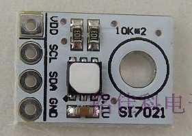
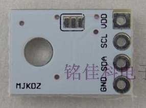
Si7021模块从淘宝购买,原来以为板子自带I2C上拉电阻的,后来才发现模块的上拉电阻并没有焊接到VDD上,还需要自己把背面三个焊点焊在一起才行。


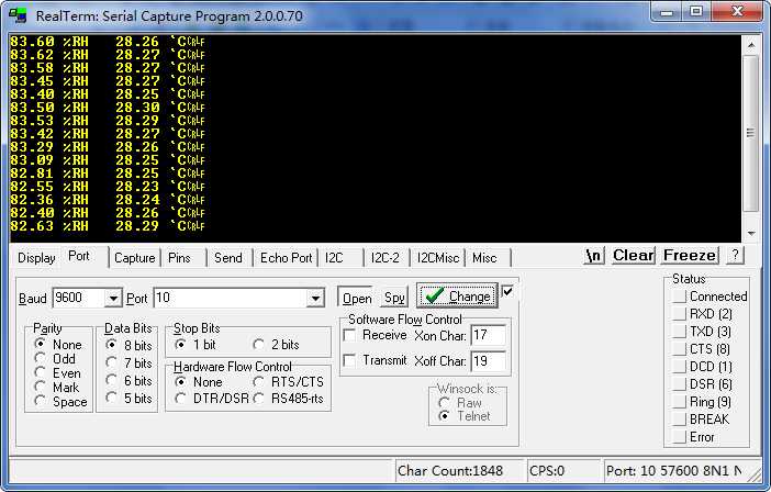
以下代码每隔2s测量一次温湿度,并通过串口打印结果。printf()函数的使用可参考之前另一篇文章。

  1 // msp430G2553 i2c bus <-> Si7021 humidity & temperature sensor
  2 // pullup resistors for SDA & SCL lines: 10kOhm
  3 // jumper for LED2 should be removed, or I2C bus won‘t work.
  4
  5 #include "io430.h"
  6 #include "TI_USCI_I2C_master.h"
  7
  8 #define SI7021_ADDRESS 0x40
  9 #define MEASURE_RH_HOLD 0xE5
 10 #define MEASURE_RH_NO_HOLD 0xF5
 11 #define READ_T_FROM_PRE_RH_MEASUREMENT 0xE0
 12
 13 #define RXD BIT1 //P1.1
 14 #define TXD BIT2 //P1.2
 15
 16 unsigned char array[1] = {0};
 17 unsigned char store[3] = {0, 0, 0};
 18 unsigned int outHumi = 0;
 19 float valueHumi = 0.0;
 20 int outTemp = 0;
 21 float valueTemp = 0.0;
 22
 23 // functions for printf()
 24 void sendByte(unsigned char);
 25 void printf(char *, ...);
 26 void initUART(void);
 27 void printf_f(float);
 28
 29 void main( void )
 30 {
 31     // Stop watchdog timer to prevent time out reset
 32     WDTCTL = WDTPW + WDTHOLD;
 33
 34     // DCO setup
 35     BCSCTL1 = CALBC1_1MHZ;
 36     DCOCTL = CALDCO_1MHZ;
 37
 38     // UART setup
 39     initUART();
 40
 41     __enable_interrupt();
 42
 43     while(1)
 44     {
 45         TI_USCI_I2C_transmitinit(SI7021_ADDRESS, 10); // init transmitting with USCI
 46         // scl clock: f(BRCLK)/10; BRCLK <- SMCLK
 47         while(TI_USCI_I2C_notready()); // wait for bus to be free
 48
 49         array[0] = MEASURE_RH_NO_HOLD;
 50         TI_USCI_I2C_transmit(1, array);
 51         while(TI_USCI_I2C_notready());
 52
 53         __delay_cycles(25000); //delay 25ms
 54
 55         // get the humidity result
 56         TI_USCI_I2C_receiveinit(SI7021_ADDRESS, 10);
 57         while(TI_USCI_I2C_notready());
 58
 59         TI_USCI_I2C_receive(3,store);
 60         while(TI_USCI_I2C_notready());
 61
 62         outHumi = (store[0]<<8) | store[1];
 63         valueHumi = 125.0*outHumi/65536 - 6;
 64
 65         //printf("heX            %x\r\n", outHumi);
 66         //printf("heX            %x\r\n", (unsigned int)store[2]);
 67         //printf("Integer        %i\r\n", (int)valueHumi);
 68         printf_f(valueHumi);
 69         printf(" %%RH   ");
 70
 71
 72         // get temperature from previous RH measurement
 73         TI_USCI_I2C_transmitinit(SI7021_ADDRESS, 10);
 74         while(TI_USCI_I2C_notready());
 75         array[0] = READ_T_FROM_PRE_RH_MEASUREMENT;
 76         TI_USCI_I2C_transmit(1, array);
 77         while(TI_USCI_I2C_notready());
 78
 79         TI_USCI_I2C_receiveinit(SI7021_ADDRESS, 10); // init receiving with USCI
 80         while(TI_USCI_I2C_notready()); // wait for bus to be free
 81         TI_USCI_I2C_receive(2,store);
 82         while(TI_USCI_I2C_notready());
 83
 84         outTemp = (store[0]<<8) | store[1];
 85         valueTemp = 175.72*outTemp/65536 - 46.85;
 86
 87         //printf("heX            %x\r\n", outTemp);
 88         //printf("Integer        %i\r\n", (int)valueTemp);
 89         printf_f(valueTemp);
 90         printf(" `C\r\n");
 91
 92         __delay_cycles(2000000); //delay 2s
 93     }
 94 }
 95
 96 void initUART(void) {
 97     //config P1.1 RXD, P1.2 TXD
 98     P1SEL |= TXD + RXD;
 99     P1SEL2 |= TXD + RXD;
100
101     //reset UCA0, to be configured
102     UCA0CTL1 = UCSWRST;
103     //config
104     UCA0CTL1 |= UCSSEL_2; //SMCLK
105     UCA0BR0 = 104;
106     UCA0BR1 = 0;//1MHz baut rate = 9600
107     UCA0MCTL = UCBRS0; // Modulation UCBRSx = 1
108     //make UCA0 out of reset
109     UCA0CTL1 &= ~UCSWRST;
110 }
111
112 void sendByte(unsigned char byte )
113 {
114     while (!(IFG2&UCA0TXIFG));            // USCI_A0 TX buffer ready?
115     UCA0TXBUF = byte;                // TX -> RXed character
116 }
117
118 void printf_f(float fnumber)
119 {
120     int ipart = (int)fnumber; // integer part
121     int fpart = (int)((fnumber - ipart)*100); //fractional part, 2 decimal places
122
123     printf("%i.", ipart);
124
125     if(fpart<0)
126     {
127         fpart = -fpart;
128     }
129     if(fpart<10)
130     {
131         printf("0");
132     }
133     printf("%i", fpart);
134 }
程序输出结果如图所示。

标签:
原文地址:http://www.cnblogs.com/zlbg/p/4858509.html