标签:
Bootrom (or Boot ROM) is a small piece of mask ROM or write-protected flash embedded inside the processor chip.
It contains the very first code which is executed by the processor on power-on or reset.
Depending on the configuration of some strap pins or internal fuses it may decide from where to load the next part of the code to be executed
and how or whether to verify it for correctness or validity.
Sometimes it may contain additional functionality, possibly usable by user code during or after booting. Some examples:
NXP‘s LPCxxxx series Boot ROM.
Placed in a hidden portion of the internal flash which is mapped at 0 on power-on.
Implements CRP (code read protection), ISP (In-System Programming) which allows to upload and flash new code over UART.
If a valid user code is in flash (needs to have proper checksum), maps it to 0 and jumps to it.
A part of bootrom remains mapped to provide IAP (In-Application Programming) and some other services.
Bootloader is responsible for finding and loading the final OS or firmware which is supposed to run on the chip.
One main difference from bootrom is that it‘s usually in writable flash and can be replaced or upgraded.
Sometimes bootrom can perform the job of the bootloader.
For example, OMAP‘s bootrom is complex enough (it can parse FAT32!) that you can probably have it load and start a Linux kernel directly.
However, in many cases a separate bootloader is used, either because the bootrom is not capable enough (or absent), or because extra flexibility is needed.
It can be very simple (load kernel from a fixed flash location in RAM and jump to it), or can be much more complicated.
For example, U-Bootis a like a mini-OS by itself - it has a console, some commands, allows you break the boot process
and e.g. modify the kernel command line arguments or even load the kernel from a different location (SD/MMC or USB), run some tests and so on.
Bootloaders are usually used when you have a more or less complex OS which may need some set up before it can be started.
Smaller microcontrollers like NXP‘s LPC series usually use a monolithic firmware so they can get by without it (however,
there may be custom bootloaders for them too).
On the very simplest chips there may be no boot ROM or boot loader at all - they just try to fetch and execute instructions from a fixed startup address.
In fact, most x86 chips to this day work like this - they just start executing code at FFFFFFF0 with the expectation that the chipset has mapped the BIOS flash chip there.
Here, you can say that BIOS is the bootloader (though it also provides services to the OS, similar to bootrom).
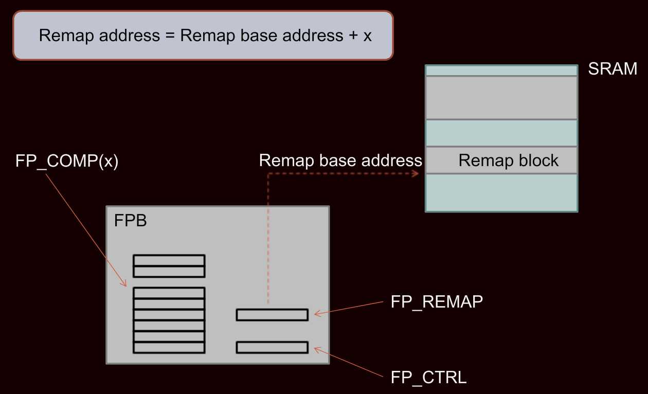
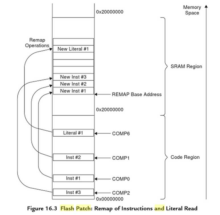
ARM processor cores implementing the v7-M architecture, currently Cortex-M3 and Cortex-M4, include a component called the "Flash Patch and Breakpoint" Unit (FPB).
Besides being used by debug tools to provide a hardware breakpoint mechanism, FPB provides a mechanism for patching immutable program code
or literal constants in firmware by redirecting memory accesses.
This paper will show you an MCU-vendor independent approach to do this.
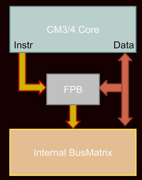
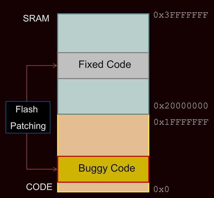
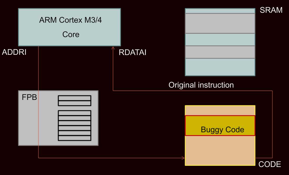
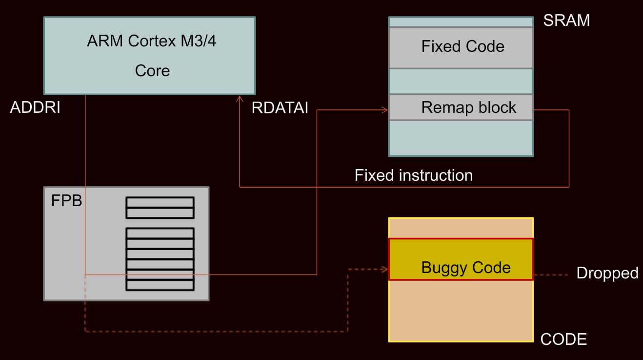
The LPC43xx contains USB DFU bootloader support in ROM. By selecting the appropriate boot mode (USB0), the device will come up on USB at power-up or reset, and implement the popular and well-documented USB DFU protocol.
Set the boot mode jumpers to USB0: BOOT[0:3] = "1010". Jumper setting takes effect at the next power-on or reset. (You can rig up a reset button to P2 "LPC_JTAG" or P14 "LPC_ISP".)
You need the latest source from git for some reason.
DFU boot downloads to RAM then executes. Need a DFU suffix, but also a header
cp blinky.bin blinky.dfu
Add DFU suffix and address prefix:
/usr/local/bin/dfu-suffix --pid=0x000c --vid=0x1fc9 --did=0x0 -s 0 -a blinky.dfu
Create header (based on UM10503 section 5.3.3 "Boot image header format"):
echo "0000000: da ff {blocksL} {blocksH} {hash0} {hash1} {hash2} {hash3}" | xxd -g1 -r > header.bin
where {blocksL} and {blocksH} are the low and high bytes of the length of the .bin file + 16 bytes, measured in 512-byte frames. "02 00" means 2 x 512 + 16 bytes. (this should be automated.) Assume rounded up.
{hash0}..{hash3} = 0xFF. The value is not used, based on the HASH_ACTIVE field in the first two bytes.
Add header
cat header.bin blinky.dfu > load.dfu
Check for device:
/usr/local/bin/dfu-util -l
Download (I used the latest dfu-util from git)
/usr/local/bin/dfu-util -d 1fc9:000c -a 0 -D load.dfu
Also make sure that the binary is linked for execution at address 0x00000000. This is the default for our linker scripts.
A 12 MHz clock signal must be supplied to the LPC4330 at boot time.
The April 16, 2012 Jellybean design has a voltage divider for VBUS that is fed to the LPC43xx to detect that a USB host is present.
Measuring the divided voltage, the USB0_VBUS only reaches 0.4V, which fails to trip the USB bootloader code.
It looks like NXP‘s intent is to directly connect VBUS to the USB0_VBUS.
Indeed, when I shorted R10 with tweezers, the USB bootloader sprung into action.
I would recommend changing R10 to 0 Ohms and R11 to DNP, or removing R10 and R11 altogether.
How do I use USB DFU mode to upload firmware onto a LPC18xx/LPC43xx device?
The device starts up into DFU mode correctly and shows up using lsusb and dfu-util under Linux as well as under Windows. It fails on the first download command.
Are there any documents available describing NXP‘s version of the DFU protocol? Is custom software needed?
Useful links:
http://vusb-analyzer.sourceforge.net/
http://www.usb.org/developers/devclass_docs/usbdfu10.pdf
Thank you for your help. I am now able to successfully download and upload firmware onto my LPC1850 using DFU-Util under Linux and Windows.
A Windows version of DFU-Util can be found. A version also comes with the Maple IDE.
Loading firmware using USB DFU Mode:
The -R switch will reset your device into the downloaded firmware after download is complete.
Output under Windows:
C:\>dfu-util.exe -R -D FIRMWARE_withHeader.bin
dfu-util - (C) 2007-2008 by OpenMoko Inc.
This program is Free Software and has ABSOLUTELY NO WARRANTY

Opening USB Device 0x0000:0x0000...
Setting Configuration 1...
Claiming USB DFU Runtime Interface...
Determining device status: state = appIDLE, status = 0
Device really in Runtime Mode, send DFU detach request...
Resetting USB...
Opening USB Device...
Found Runtime: [0x1fc9:0x000c] devnum=5, cfg=0, intf=0, alt=0, name="DFU"
Setting Configuration 1...
Claiming USB DFU Interface...
Setting Alternate Setting ...
Determining device status: state = dfuIDLE, status = 0
dfuIDLE, continuing
Transfer Size = 0x0800
bytes_per_hash=440
Starting download: [##################################################] finished!
unable to read DFU status
we have DFU loading ok nice on LPC4350, I assumed it MUST also work on LPC1830, but now getting really scared..
on LPC1830 we see:
Opening USB Device 0x0000:0x0000...
Setting Configuration 1...
Claiming USB DFU Runtime Interface...
Determining device status: state = appIDLE, status = 0
Device really in Runtime Mode, send DFU detach request...
Resetting USB...
Opening USB Device...
Found Runtime: [0x1fc9:0x000c] devnum=2, cfg=0, intf=0, alt=0, name="DFU"
Setting Configuration 1...
Claiming USB DFU Interface...
Setting Alternate Setting ...
Determining device status: state = dfuIDLE, status = 0
dfuIDLE, continuing
Transfer Size = 0x0800
bytes_per_hash=102
Starting download: [##################################################] finished!
When the LPC18xx and LPC43xx family of parts boot up over USB they sends a DFU descriptor up to the host but they do not support the full set of DFU functions.
They can only download an image into RAM and jump to it. That‘s it.
To implement a DFU driver you will need to create an image that contains this driver and download and run it as a second stage.
This has all been done here: http://lpcware.com/content/project/dfu-download-programming-utility-and-security-lpcdfusec-tool
The utility that downloads the image when the parts are booting up over USB is a C# application that sits on top of WinUSB.
Source code to this application can be obtained with an NDA. Contact your FAE to do this.
Source code to the second stage DFU driver that works with dfu-util can be found in the applications\lpc18xx_43xx\examples\dfuutil folder of the latest LPCOpen Platform release for this part which can be found here: http://lpcware.com/content/project/lpcopen-platform-nxp-lpc-microcontrollers
If that‘s the case, do you think do a 2 stage dfu-util code download will work?
* dfu-util -D bootloader_second_stage.bin.hdr (with header)
* dfu-util -R -D firmware.bin ( no header)
bootloader_second_stage.bin is compiled from the second stage dfu drivers. Thanks.
I implemented the second stage, if you are interested you can download the file here
http://www.lancos.com/lpc_dfu-1.02.tar.gz
Claudio
We want to use the USB/DFU mechanism to update our firmware.
The USB/DFU loader is already implementetd in the boot rom.
The USB/DFU loader starts normally on power up if the Boot mode = USB0
and the boot pin P2_7 = high.
This works.
But we want to jump to the USB/DFU loader (in the boot rom) from our firmware (in the internal flash).
How can we jump to the USB/DFU loader (without reset, without powerup, without P2_7 = high) ?
Background: We don‘t want to have a boot jumper.
It‘s possible to do something like that. The principle flow is the following:
- wind back the MCU status to reset state as much as possible
- jump to the bootcode
- use the flash patch unit (part of Cortex-Mx system) to prevent from executing the normal bootloader flow (ignore ISP and bootmode pins)
Attached is a minimized project which is exactly doing this for the LPC1857 and LPC4357 (xx53 and xx33 are supported as well).
The LPC1850 and LPC4350 (flashless parts) have a different bootloader, so the software needs to be changed for these chip types.
Please test it if it works for you, we don‘t officially support this method
Regards,
NXP Support Team
I‘m trying this code on an LPC4337 chip, but it don‘t work.
Where can I find ROM memory address for this chip ?
I need following address :
// Clocks_Init
// tmBootRomConfig_Clocks_and_Pins
// tmBootRomISP_init
// tmBootRomISP_run
Thank you.
OK, here is the new project which is running on the following chips:
All required information how to deal with it is embedded in the source code in file main.c.
If you see any issues with please post it here.
Regards,
NXP Support Team
Anyway, I tested my project again, changed the code here and there to the 12.1 bootcode and it works.
I attached the main.c for exactly this configuration, so please make a crosscheck with your code.
Please notice that this project is set to LPC1857 with Cortex-M3, but it works as is on the LPC4337/57 as well.
Regards,
NXP Support Team.
//=============================================================================================================
//                                           I N T R O D U C T I O N
//=============================================================================================================
//
//  This software is a patch of the existing bootloader feature inside LPC1800 / LPC4300.
//
//  It solves the following application problem:
//    How can I enter USB0 DFU bootmode from application code without physically modifying the bootmode pins ?
//
//  The bootmode pins P1_1, P1_2, P2_8 and P2_9 determine the way the bootloader behaves. This is described in
//  detail in the user manual. If it‘s not possible to change the bootmode pins, the MCU will always start from
//  the selected bootsource. For e.g. a firmware upgrade it is very useful to set a different boot source from
//  the application code instead of performing a manual bootmode pin modification.
//
//  The patch uses the Flash Patch and Breakpoint unit of the Cortex-M to modify the existing boot ROM code.
//
//  As this is a patch, NXP gives no warranty on the final functionality. The implementation and test is up to
//  the end product manufacturer.
//  NXP will not provide source code or any additional information about the bootloader in LPC1800/4300.
//
//  This is a small stand-alone example which does not fit into any software package concept from NXP or 3rd party.
//
//  Supported MCUs:
//
//   - LPC1850/30/20/10 Rev A                                     Bootcode v11.2
//   - LPC4350/30/20/10 Rev A                                     Bootcode v11.2
//   - LPC4370                                                    Bootcode v11.2
//   - LPC1857 and all other flash based derivatives rev "-"      Bootcode v12.1
//   - LPC4357 and all other flash based derivatives rev "-"      Bootcode v12.1
//   - LPC1857 and all other flash based derivatives rev "A"      Bootcode v12.2  (Q4/2014)
//   - LPC4357 and all other flash based derivatives rev "A"      Bootcode v12.2  (Q4/2014)

//
//=============================================================================================================

#ifdef CORE_M4
  #include "LPC43xx.h"
#endif

#ifdef CORE_M3
  #include "LPC18xx.h"
#endif


// Define registers of the Flash Patch and Breakpoint unit (FPB).
// This is part of the Cortex-M3/M4 core and is described in detail in the ARMv7-M Architecture Reference Manual
typedef struct {
    __IO uint32_t CTRL;
    __IO uint32_t REMAP;
    __IO uint32_t CODE_COMP[6];
    __IO uint32_t LIT_COMP[2];
} FPB_Type;

#define FPB ((FPB_Type *)0xE0002000)

// The FPB contains both a global enable and individual enables for the eight comparators. If the
// comparison for an entry matches, the address is remapped to the address set in the remap register
// plus an offset corresponding to the comparator that matched.


//#############################################################################################################
//                                                M A I N
//#############################################################################################################
int main (void)
{
  volatile int i;

    // This delay is just for debug purposes, in order to get access with a debugger before
    // more "dreadful things" could happen ;-)
  for (i = 0; i < 10000000; i++);


  //=============================================================================================================
    //                                           T U T O R I A L
    //=============================================================================================================
    //
    // STEP #1:  Wind back MCU to a state which is similar to the system state after a normal bootloader run.
    //           This could be pretty application specific, therefore the implementation and test is individual.
    //           But the following 3 steps need to be integrated into your application code.
    //
    // Example:  - set the PLL back to 96 MHz (bootloader also sets it to 96MHz)
    //           - reset as many peripherals as possible.
  //             LPC_RGU->RESET_CTRL0 = 0x387F1200;   // this works for LPC1857/37/33 etc and LPC4357/37/33 etc in rev. "-"
  //             LPC_RGU->RESET_CTRL1 = 0x17FFF7FF;   // this works for LPC1857/37/33 etc and LPC4357/37/33 etc in rev. "-"


  // Disable or wind back settings of your application code
    // < code here>

    // Reset as many peripherals as possible in LPC4357 and LPC1857
    LPC_RGU->RESET_CTRL0 = 0x387F1200;  // this should work for LPC1857/37/33 etc and LPC4357/37/33 etc with bootcode v12.1
  LPC_RGU->RESET_CTRL1 = 0x17FFF7FF;  // this should work for LPC1857/37/33 etc and LPC4357/37/33 etc with bootcode v12.1

  // Resets for LPC4350 and LPC1850 (bootcode v11.2) needs to be tested
    // Start with a single bit and then add bit by bit.
    // Doing no reset at least seems to work in a first step.
  //LPC_RGU->RESET_CTRL0 = 0x????????;
  //LPC_RGU->RESET_CTRL1 = 0x????????;


  //=============================================================================================================
    //                                           T U T O R I A L
    //=============================================================================================================
    //
    // STEP #2:  Set up the Flash Patch and Breakpoint unit (FPB) in such a way that the result from a bootmode pin
    //           query is faked. The level on the boot pins are latched after reset by hardware, so there‘s nothing
    //           you can do here. But the bootloader will ask for the result in one of its functions, and this is
    //           where we jump in: if the bootloader comes to a specific address (the one we store in the
    //           FPB CODE_COMP register) the ARM will fetch the code from the SRAM location we defined in the REMAP
    //           register. The code in this case is pretty simple, we just store 0x15 in R0, the effect is simply
    //           that we replaced the true level of the bootcode pins by a faked level, 0x15 means USB0 DFU bootmode.
    //
    // Note:  Please keep in mind that a debugger also uses the FPB to set breakpoints (also "Run to Cursor" creates
    //        a breakpoint). So if you think you need to debug into this code, then please be aware that the
    //        debugger will change the FPB settings without letting you know ;-)


  // Set SRAM location for patch code
    FPB->REMAP = 0x20000000;         // REMAP table @ 0x20000000

    // Define the patch code instructions
  ((volatile uint32_t *)0x20000000)[0] = 0x20152015;  // movs r0,#0x15 (2x)

    // Set the address comperator  (must be an odd address)
    // Required address from boot ROM v12.1  (e.g. LPC1857 rev. "-")
  FPB->CODE_COMP[0] = 0x10401A04 | 0x00000001;

  // Required address from boot ROM v11.2  (e.g. LPC1850 rev. A)
  //FPB->CODE_COMP[0] = 0x10400F64 | 0x00000001;

  // Required address from boot ROM v12.2   (e.g. LPC1857 rev. A)
  //FPB->CODE_COMP[0] = 0x10402404 | 0x00000001;

    // Enable the FPB unit
  FPB->CTRL = 0x00000003;


  //=============================================================================================================
    //                                           T U T O R I A L
    //=============================================================================================================
    //
    // STEP #3:   Jump to bootcode functions in ROM in order to end up in DFU bootmode.
    //            These are individual for each boot ROM version.
    //            In the last function tmBootRomISP_run the bootloader will enter, as required, the USB0 DFU bootmode
    //            and the board should appear in the device manager of a PC as "LpcDevice"


  // Enable the clock for Random Number Generator inside the internal flash block. This is required for a correct
    // operation of the bootloader code for the flash types LPC1857/4357.
    // This is NOT required for the LPC1850/4350, because there is no internal flash.
    // This bit is not documented in the LPC1857/4357 user manual.
  LPC_CREG->CREG6 &= ~(1u << 17);    // please comment out for LPC1850/4350


  // Please remember what has been said before:
    // ==========================================
  // If you debug into this section using breakpoints or "Run to Cursor", then your settings of the FPB were
    // changed by the debugger in the background, therefore the expected code replacement will not take place.

    // Addresses from boot ROM v12.1  (e.g. LPC1857 rev. "-")
  ((void(*)(int))0x1040214D)(LPC_OTP_BASE);   // Clocks_Init
  ((void(*)(int))0x104021C1)(LPC_OTP_BASE);   // tmBootRomConfig_Clocks_and_Pins
  ((void(*)(int))0x104038DF)(LPC_OTP_BASE);   // tmBootRomISP_init
  ((void(*)(int))0x104038F3)(LPC_OTP_BASE);   // tmBootRomISP_run
/*
    // Addresses from ROM 11.2  (e.g. LPC1850 rev. A)
  ((void(*)(int))0x104014B9)(LPC_OTP_BASE);   // Clocks_Init
  ((void(*)(int))0x10400A05)(LPC_OTP_BASE);   // tmBootRomSrc_init
  ((void(*)(int))0x10400A27)(LPC_OTP_BASE);   // tmBootRomSrc_start

    // Addresses from boot ROM v12.2  (e.g. LPC1857 rev. A)
  ((void(*)(int))0x10402B4D)(LPC_OTP_BASE);   // Clocks_Init
  ((void(*)(int))0x10402D43)(LPC_OTP_BASE);   // tmBootRomConfig_Clocks_and_Pins
  ((void(*)(int))0x10405563)(LPC_OTP_BASE);   // tmBootRomISP_init
  ((void(*)(int))0x10405577)(LPC_OTP_BASE);   // tmBootRomISP_run
*/

    while (1)  // we will never come here if everything worked as planned
  ;
}
LPC18xx LPC43xx LPC4370 Bootrom USB DFU FPB - Flash Patch and Breakpoint Unit
标签:
原文地址:http://www.cnblogs.com/shangdawei/p/4963017.html