标签:
旋转编码器可通过旋转可以计数正方向和反方向转动过程中输出脉冲的次数,旋转计数不像电位计,这种转动计数是没有限制的。配合旋转编码器上的按键,可以复位到初始状态,即从0开始计数。
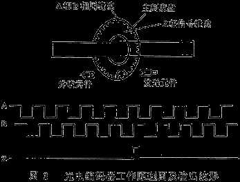
工作原理: 增量编码器是一种将旋转位移转换为一连串数字脉冲信号的旋转式传感器。这些脉冲用来控制角位移。在Eltra编码器中角位移的转换采用了光电扫描原理。读数系统以由交替的透光窗口和不透光窗口构成的径向分度盘(码盘)的旋转为依据,同时被一个红外光源垂直照射,光把码盘的图像投射到接收器表面上。接收器覆盖着一层衍射光栅,它具有和码盘相同的窗口宽度。接收器的工作是感受光盘转动所产生的变化,然后将光变化转换成相应的电变化。再使低电平信号上升到较高电平,并产生没有任何干扰的方形脉冲,这就必须用电子电路来处理。读数系统通常采用差分方式,即将两个波形一样但相位差为180°的不同信号进行比较,以便提高输出信号的质量和稳定性。读数是再两个信号的差别基础上形成的,从而消除了干扰。
|
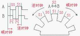
顺时针运动 |
逆时针运动 |
|
A B 1 1 0 1 0 0 1 0 |
A B 1 1 1 0 0 0 0 1 |
增量编码器

增量编码器给出两相方波,它们的相位差90°,通常称为A通道和B通道。其中一个通道给出与转速相关的信息,与此同时,通过两个通道信号进行顺序对比,得到旋转方向的信息。还有一个特殊信号称为Z或零通道,该通道给出编码器的绝对零位,此信号是一个方波与A通道方波的中心线重合。

增量型编码器精度取决于机械和电气两种因素,这些因素有:光栅分度误差、光盘偏心、轴承偏心、电子读数装置引入的误差以及光学部分的不精确性。确定编码器精度的测量单位是电气上的度数,编码器精度决定了编码器产生的脉冲分度。以下用360°电气度数来表示机械轴的转动,而轴的转动必须是一个完整的周期。要知道多少机械角度相当于电气上的360度,可以用下列公式来计算: 电气360 =机械360°/n°脉冲/转

图:A、B换向时信号
编码器分度误差是以电气角度为单位的两个连续脉冲波的最大偏移来表示。误差存在于任何编码器中,这是由前述各因素引起的。Eltra编码器的最大误差为±25电气角度(在已声明的任何条件下),相当于额定值偏移±7%,至于相位差90°(电气上)的两个通道的最大偏差为±35电气度数相当于额定值偏移±10%左右。
UVW信号增量型编码器
除了上述传统的编码器外,还有一些是与其它的电气输出信号集成在一起的增量型编码器。与UVW信号集成的增量型编码器就是实例,它通常应用于交流伺服电机的反馈。这些磁极信号一般出现在交流伺服电机中,UVW信号一般是通过模拟磁性原件的功能而设计的。在Eltra编码器中,这些UVW信号是用光学方法产生,并以三个方波的形式出现,它们彼此偏移120°。为了便于电机启动,控制电动机用的启动器需要这些正确的信号。这些UVW磁极脉冲可在机械轴旋转中重复许多次,因为它们直接取决于所连接的电机磁极数,并且用于4、6或更多极电机的UVW信号。
》》》》》》》》
了解了原理之后,我编写verilog代码,并在STEP小脚丫FPGA板子上做了验证。
代码如下:
  1 //   ==================================================================
  2 //       >>>>>>>>>>>>>>>>>>>>>>>  NOTICE <<<<<<<<<<<<<<<<<<<<<<<<<
  3 //   ------------------------------------------------------------------
  4 //   Copyright (c) 2015 by v_jiaocheng
  5 //   ALL RIGHTS RESERVED
  6 //   ------------------------------------------------------------------
  7 //
  8 //   Permission:
  9 //        To use this code please let me now.
 10 //   Disclaimer:
 11 //
 12 //      This VHDL or Verilog source code is intended as a design reference
 13 //      which illustrates how these types of functions can be implemented.
 14 //      It is the user‘s responsibility to verify their design for
 15 //      consistency and functionality through the use of formal
 16 //      verification methods.  We provides no warranty
 17 //      regarding the use or functionality of this code.
 18 //
 19 //   --------------------------------------------------------------------
 20 //
 21 //                  Wechat Official Accounts :    v_jiaocheng
 22
 23 //                  TEL:  (USA and Canada)
 24 //                        (Singapore)
 25 //                        (other locations)
 26 //
 27 //                  web: http://www.znczz.com/forum-234-1.html
 28 //                  email: ning.pg@qq.com
 29 //
 30 //   -------------------------------------------------------------------
 31 //  Project:           encoder
 32 //  File:              encoder.v
 33 //  Title:             encoder
 34 //  Description:       Test the encoder‘s functions with folw LEDs
 35 //
 36 // --------------------------------------------------------------------
 37 // Code Revision History :
 38 // --------------------------------------------------------------------
 39 // Ver: | Author:tony-ning  | Mod. Date  | Changes Made:
 40 // V1.0 | H.C.                 | 2015-11-18 | Initial Release
 41 //
 42 // --------------------------------------------------------------------
 43
 44
 45
 46 module Rotation_encoder
 47 (
 48     input                             CLK,              //25MHz system clk
 49     input                             sig_A,            //encoder A channal
 50     input                             sig_B,            //encoder B channal
 51     input                             BUTTON_IN,        //encoder‘s key signal
 52     output                            [6:1]Led_out      //trible LEDs(active low)
 53 );
 54
 55     //The definitions for encoder states
 56     parameter IDLE=2‘b11;
 57     parameter s1=2‘b01;
 58     parameter s2=2‘b00;
 59     parameter s3=2‘b10;
 60
 61
 62     reg [1:0]p;                //The state register of the current state machine
 63     reg [1:0]p_pre;            //The state register of the pre state machine
 64     reg [24:0]count2;         //Counter of debounce module
 65     reg up,down;              //The register of encoder‘s increse/decrese action
 66     reg key_reg1,key_reg2;     //The temp register of encoder‘s key state
 67     reg key_out;               //The register of encoder-key‘s negedge after debounce
 68     reg [6:1]rled=6‘b111110;   //LEDs registers and the default  state(if(up)ring shift left)
 69
 70     //Judging the encoder‘s motion,every trun left up will add 1,so as the down
 71     always @( posedge CLK)
 72         begin
 73             p<={sig_A,sig_B};                        //Get current state
 74             p_pre<=p;                                //Get pre state
 75             case(p_pre)
 76             //check current and pre state to judge the motion
 77             IDLE:begin
 78                     if(up | down) begin
 79                         up<=0;
 80                         down<=0;
 81                     end else begin
 82                         if(p==s1)
 83                             up<=1;
 84                         if(p==s3)
 85                             down<=1;
 86                     end
 87                 end
 88             s1:    begin
 89                     if(up | down) begin
 90                         up<=0;
 91                         down<=0;
 92                     end else begin
 93                         if(p==s2)
 94                             up<=1;
 95                         if(p==IDLE)
 96                             down<=1;
 97                     end
 98                 end
 99             s2:    begin
100                     if(up | down) begin
101                         up<=0;
102                         down<=0;
103                     end else begin
104                         if(p==s3)
105                             up<=1;
106                         if(p==s1)
107                             down<=1;
108                     end
109                 end
110             s3:    begin
111                     if(up | down) begin
112                         up<=0;
113                         down<=0;
114                     end else begin
115                         if(p==IDLE)
116                             up<=1;
117                         if(p==s2)
118                             down<=1;
119                     end
120                 end
121             endcase
122         end
123
124     //Key of encoder input debounce
125     always @( posedge CLK)                            //System CLK 25M
126         begin
127             count2<=count2+1;
128             if(count2==250000) begin
129                 key_reg1<=BUTTON_IN;                 //every 10ms updata
130                 count2<=0;
131             end
132             key_reg2<=key_reg1;                      //every CLK check,so can make a single CLK pulse
133             key_out<=key_reg2&(!key_reg1);
134         end
135
136     //LEDs output based the encoder‘s motion
137     always @( posedge CLK)
138         if(up)
139             rled<={rled[5:1],rled[6]};               //Leds folw left if clockwise rotation
140         else
141             if(down)
142                 rled<={rled[1],rled[6:2]};
143             else
144                 if(key_out)
145                     rled<={rled[5:1],rled[6]};
146
147     assign Led_out=rled;
148
149
150
151 endmodule
标签:
原文地址:http://www.cnblogs.com/tony-ning/p/4974046.html