标签:
A Universal Asynchronous Receiver and Transmitter (UART) in Exynos 4412 SCP provide four independent
Exynos 4412 SCP 的UART提供了4个异步串口通道(ch0~3)。还提供的ch4专用通道给GPS。
channels with asynchronous and serial input/output (I/O) ports for general purpose (Ch0 to 3). It also provides a
串口有两种工作模式:中断模式和DMA模式。
dedicated channel for communication with Global Positioning System (GPS) (Ch4). All the ports operate either in
UART通过产生中断或DMA请求来收发数据。
an interrupt-based or a DMA-based mode. UART generates either an interrupt or a DMA request to transfer data
to and from CPU and UART. UART supports bit rates up to 4 Mbps. Each UART channel contains two First In
UART支持最高码率4Mbps。每个通道包含两个FIFO,用于发送、接收缓冲。
First Outs (FIFOs) to receive and transmit data as in:
- 256 bytes in Ch0 ch0的缓冲区大小为256字节
- 64 bytes in Ch1 and Ch4 ch1和ch4的缓冲区大小为64字节
- 16 bytes in Ch2 and Ch3 ch2和ch3的缓冲区大小为16字节
UART includes:
- Programmable Baud rates 可编程的波特率
- Infrared (IR) transmitter/receiver 红外发射接收
- One or two stop bit insertion 1或2位的停止位
- 5-bit, 6-bit, 7-bit, or 8-bit data width and parity checking 5、6、7、8数据位,1位校验位
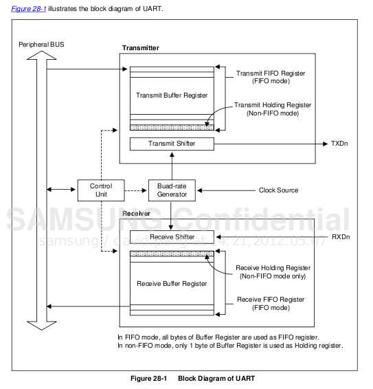
As shown in
Figure 28-1, each UART contains:
- Baud-rate generator 波特率产生器
- Transmitter 发送单元
- Receiver 接收单元
- Control unit 控制单元
The Baud-rate generator uses SCLK_UART. The transmitter and the receiver contain FIFOs and data shifters.
The data to be transmitted is written to Tx FIFO, and copied to the transmit shifter. The data is then shifted out by
the transmit data pin (TxDn). The received data is shifted from the receive data pin (RxDn), and copied to Rx FIFO
from the shifter.
要发送的数据写入Tx FIFO 寄存器(FIFO mode)或 Tx Holding 寄存器(Non-FIFO mode),接着拷贝到transmit shifter,transmit shfter中的数据通过TXDn输出。
Features of UART are:
- RxD0, TxD0, RxD1, TxD1, RxD2, TxD2, RxD3, and TxD3 with either DMA-based or interrupt-based operation
- UART Ch 0, 1, 2, and 3 with IrDA 1.0
- UART Ch 0 with 256 byte FIFO, Ch 1 and 4 with 64 byte FIFO, Ch 2 and 3 with 16 byte FIFO
- UART Ch 0, 1, 2 with nRTS0, nCTS0, nRTS1, nCTS1, nCTS2, and nRTS2 for Auto Flow Control (AFC)
- UART Ch 4 communicates with GPS and it supports AFC
- UART supports handshakes transmit/receive.
Data Transmission
The data frame for transmission is programmable. It consists of these bits that are specified by the line control 发送的数据帧可编程。由ULCONn寄存器设置:
register (ULCONn):
- A Start bit 1个开始位
- Five to eight data bits 5~8数据位
- An optional parity bit 可选的奇偶校验位
- One to two stop bits 1~2停止位 通常的串口使用115200bps,8N1
The transmitter also produces a break condition that forces the serial output to logic 0 state for one-frame
发送单元也可以产生一个终止条件,在一帧数据发送时间内强制串口输出逻辑0状态。
transmission time. This block transmits the break signals after it completely transmits the present transmission
word. After the break signal transmission, the transmitter continuously transmits data to Tx FIFO (Tx holding
register, in case of non-FIFO mode).
Data Reception
The data frame for reception is also programmable. It consists of a start bit, five to eight data bits, an optional
parity bit, and one to two stop bits in the line control register (ULCONn). The receiver detects these errors and
each of these errors sets an error flag:
- Overrun error: This error indicates that new data has overwritten the old data before the old data was read.
- Overrun error : 旧数据还未被读走就被新数据覆盖了
- Parity error: This error indicates that the receiver has detected an unexpected parity condition.
- Frame error: This error indicates that the received data does not have a valid stop bit.
- Break condition: This indicates that the RxDn input is held in the logic 0 state for more than one-frame
- Break condition: RxDn 输入引脚在超过一个数据帧的时间始终保持0状态
transmission time.
Receive time-out condition occurs when the Rx FIFO is empty in the FIFO mode and does not receive any
在FIFO模式下,当Rx FIFO为空,且在UCON指定的frame time期间没有接受到任何数据,产生超时。
data during the frame time specified in UCON.
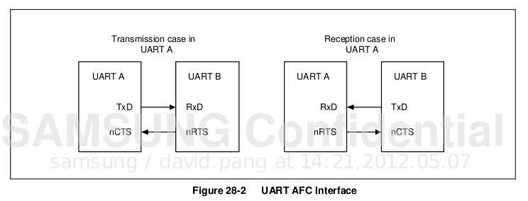
AFC(Auto Flow Control)
UART0 and UART1 in Exynos 4412 SCP support AFC by using nRTS and nCTS signals.
To connect UART to a Modem, disable the AFC bit in UMCONn register and control the signal of nRTS by using
software. The UART4 supports AFC, but it is dedicated for communication with GPS.
In AFC, the nRTS signal depends on the condition of the receiver, whereas the nCTS signals control the operation
of transmitter. The transmitter of UART transfers the data to FIFO when nCTS signals are activated In AFC, nCTS
signals means that other FIFO of UART is ready to receive data.
Before the UART receives data, nRT S has to be activated when Rx FIFO has a spare more than 2-byte and has
to be inactivated when its receive FIFO has a spare under 1-byte. In AFC, the nRTS signals means that its RX
FIFO is ready to receive data).
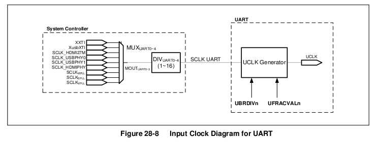
UART Input Clock Description
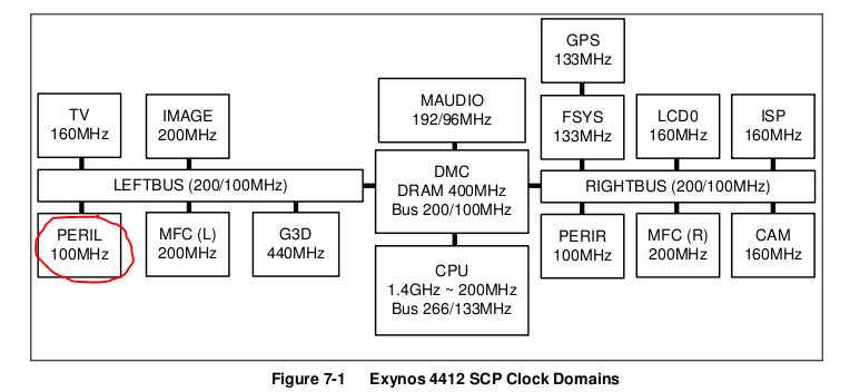
UART属于PERIL,所以SCKL_UART=100MHz
UART寄存器配置:
1.configure gpio as uart。根据底板与核心板原理图找到对应的引脚
2.configure 8N1
ULCONn = 0x3 ;
3.configure as polling mode, 还有中断模式,DMA模式
UCONn &= ~0xf ;
UCONn |= 0x5 ;
4.波特率的配置
//UBRDIVn 100M / 115200 / 16 -1 ==> 53.25
//set baudrates as 115200
UBRDIVn = 53 ;
UFRACVALn = 4 ;
UBRDIVn和UFRACVALn的计算方法:
You can use the value stored in the Baud-rate divisor (UBRDIVn) and divisor fractional value (UFRACVALn)
to determine the serial Tx/Rx clock rate (Baud rate) as:
DIV_VAL = UBRDIVn + UFRACVALn/16
or
DIV_VAL = (SCLK_UART/(bps x 16)) - 1
Where, the divisor should be from 1 to (216 – 1).
By using UFRACVALn, you can generate the Baud rate more accurately.
For example, if the Baud rate is 115200 bps and SCLK_UART is 40 MHz, UBRDIVn and UFRACVALn are:
DIV_VAL = (40000000/(115200 x 16)) – 1
= 21.7 – 1
= 20.7
UBRDIVn = 20 (integer part of DIV_VAL)
UFRACVALn/16 = 0.7
数据发送:
int putchar(char ch)
{
while(1)
{
if((UTRSTATn & (1 << 2)))//当transmitter buffer为空且transmitter shifter为空时,UTRSTATn[2]自动置1.轮询判断transmitter单元是否发送完旧数据
break;
}
UTXHn = ch ;//UTXHn存放需发送的新数据
if(ch == ‘\r‘)
putchar(‘\n‘);
return 0 ;
}
数据接收:
char getchar(void)
{
char ch ;
while(1)
{
if(UTRSTATn & 1)//当 receive buffer 有数据时,UTRSTATn[0]自动置1
break ;
}
ch = URXHn & 0xff ;//URXHn 存放接收到的数据
putchar(ch);
return ch ;
}
UART
标签:
原文地址:http://www.cnblogs.com/black-mamba/p/5027647.html