标签:
The Exynos 4412 SCP Reduced Instruction Set Computer (RISC) microprocessor supports four multi-master
Inter-Integrated Circuit (I2C) bus serial interfaces. To transmit information between bus masters and peripheral
devices, which are connected to the I2C bus, a dedicated Serial Data Line (SDA) and Serial Clock Line (SCL) is
used. Both SDA and SCL lines are bi-directional.
Exynos 4412 SCP支持4个 多主机I2c总线串行接口。通过SDA和SCL使总线上主从设备通信。SDA和SCL都是双向的。
In multi-master I2C-bus mode, multiple Exynos 4412 SCP RISC microprocessors either receive or transmit serial
data to or from slave devices. The master Exynos 4412 SCP initiates and terminates a data transfer over the I2C
bus. The I2C bus in the Exynos 4412 SCP uses a standard I2C bus arbitration procedure to realize multi-master
and multi-slave transfer.
在多主机I2C-bus模式下,多个Exynos 4412 SCP RISC microprocessors能够接收来自从设备的数据,也能向从设备发送数据。
The master Exynos 4412 SCP能启动和停止总线上数据的传输。使用标准的I2C总线仲裁实现多主和多从的数据传输。
仲裁:当多个主机试图去控制总线时,通过仲裁可以使得只有一个主机获得总线控制权,并且它传输的信息不会被破坏。
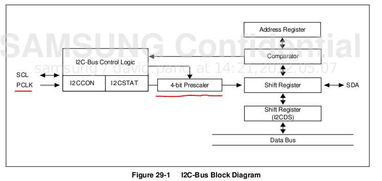
To control multi-master I2C-bus operations, you must write values to these registers:
- Multi-master I2C-bus control register – I2CCON
- Multi-master I2C-bus control/status register – I2CSTAT
- Multi-master I2C-bus Tx/Rx data shift register – I2CDS
- Multi-master I2C-bus address register – I2CADD
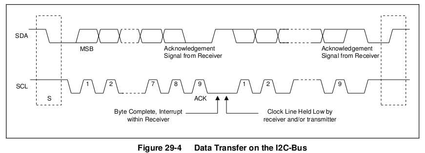
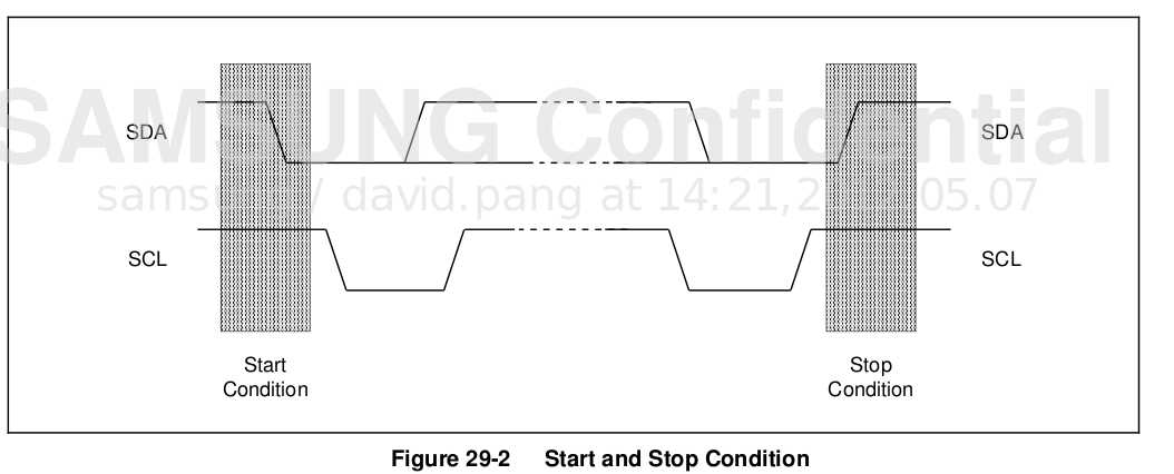
If the I2C-bus is idle, both SDA and SCL lines should be at High level. A High-to-Low transition of SDA initiates a
Start condition. A Low-to-High transition of SDA initiates a Stop condition, while SCL remains steady at High level.
I2C总线通过上拉电阻接正电源。当总线空闲时,两根线均为高电平。连到总线上的任一器件输出的低电平,都将使总线的信号变低,即各器件的SDA及SCL都是线“与”关系。
The master device always generates Start and Stop conditions. Front 7 bits address value in the data byte is
transferred through SDA line after the start condition has been initiated. This address value determines the slave
device which the bus master device has selected. The 8th bit determines the direction of the transfer (Read orWrite).
主设备控制开始与停止。当产生START后,紧接着SDA传送7位的从设备地址,第8位标识传输的方向(读或写)
The master generates START and STOP conditions.
START:
SDA: a High-to-Low transition
SCL: High
STOP:
SDA: a Low-to-High transition
SCL: High
Every byte placed on the SDA line should be 8 bits in length. There is no limit to transmit bytes per transfer.
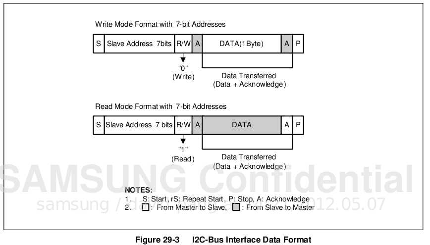
when a master initiates a START condition,it should send a slave address to notify the slave device. 1 byte of address field includes a 7-bit address and 1-bit transfer direction indicator, which shows Write or Read. When bit 8 is 0, it indicates a Write operation(TX);When bit 8 is 1, it indicates a request for data Read(Rx).
When the I2C bus is operating in master mode, master transmits the address field. An ACK bit follows each byte. The I2C controller sends first the MSB of the data and address byte to the SDA line.
Features of I2C bus interface are:
- 9 channels multi-master, Slave I2C bus interfaces
(8 channels for general purpose, 1 channel dedicated for High Definition Multimedia Interface (HDMI).)
- 7-bit addressing mode
- Serial, 8-bit oriented, and bi-directional data transfer
- Supports up to 100 kbit/s in the Standard mode
- Supports up to 400 kbit/s in the Fast mode.
- Supports master transmit, master receive, slave transmit, and slave receive operation
- Supports interrupt or polling events
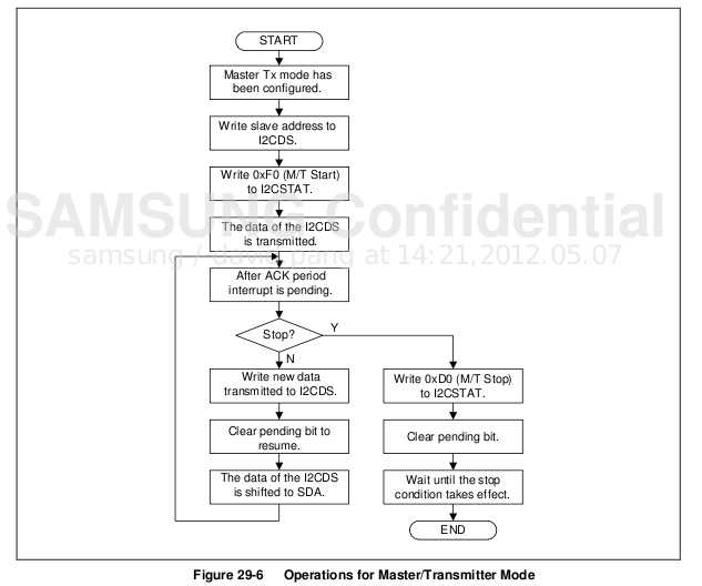
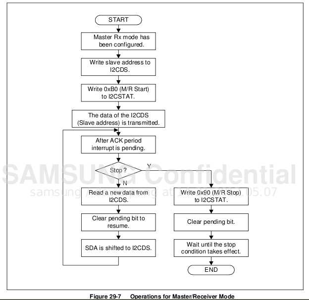
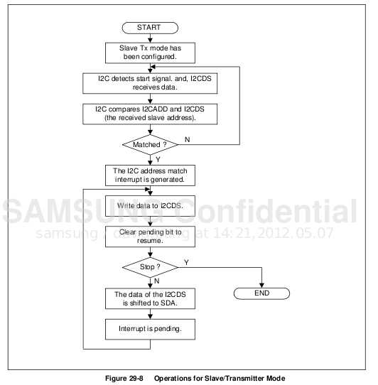
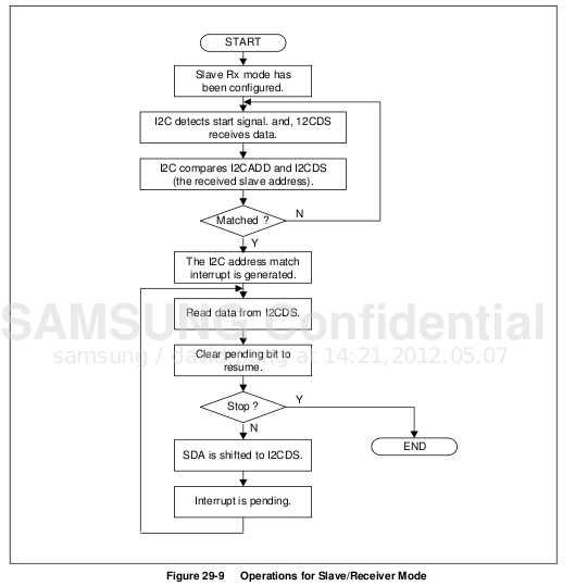
Flowcharts of Operations in Each Mode
Before you execute any I2C Tx/Rx operations:
1. If required, Write own Slave address on I2CADD register.
2. Set I2CCON register:
a) Enable interrupt.
b) Define SCL period.
3. Set I2CSTAT to enable Serial Output.
I2c
标签:
原文地址:http://www.cnblogs.com/black-mamba/p/5027895.html

