标签:
1、先讲解74LS164 移位芯片:
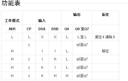
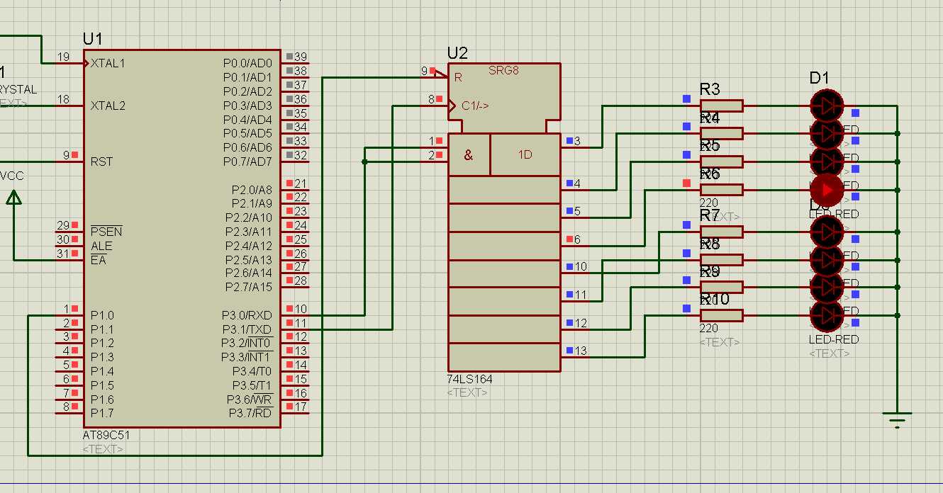
74HC164、74HCT164 是 8 位边沿触发式移位寄存器,串行输入数据,然后并行输出。
数据通过两个输入端(DSA 或 DSB)之一串行输入;任一输入端可以用作高电平使能端,控制另一输入端的数据输入。两个输入端或者连接在一起,或者把不用的输入端接高电平,一定不要悬空。
时钟 (CP) 每次由低变高时,数据右移一位,输入到 Q0, Q0 是两个数据输入端(DSA和 DSB)的逻辑与,它将上升时钟沿之前保持一个建立时间的长度。


4、参考代码:
#include<reg52.h>
#include<stdio.h>
#define uchar8 unsigned char
#define uint16 unsigned int
sbit P1_0=0x90;         // 为什么要这样写,P1口的字节地址就是 0x90 ,好像这样写也没有意义啊 // sbit LED=P0^6

uchar8 nSendByte ;

void delay(uint16 i)   // 延时函数
{
     uchar8 j;
     for(; i>0;i--)

     for(j=0;j<125;j++)
      ;

}

main()
{
    SCON=0x00;
    EA=1;      // 总中断允许
    ES=1;      // 允许串行总中断

    nSendByte = 1;     // 点亮数据初始化为 0000 0001 送入 nSendByte
    SBUF=nSendByte;     // 向 SBUF 缓冲器 写入点亮数据,启动串行发送
    P1_0=0;
    while(1)
    { ; }

}

void Serial_Port( ) interrupt 4 using 0
{

   if(T1)      // 如果 T1=1;1个字节串行发送完毕
   {
         P1_0=1;  // 也就是 0x90=1;??? 允许 74LS164芯片并行输出,流水灯点亮发光二极管

         SBUF=nSendByte;  // 像 SBUF 写入数据,启动串行发送
      delay(500);
      P1_0=0;         // P1_0=0; 允许向 74LS164 芯片 串行写入

      nSendByte = nSendByte<<1;

      if(nSendByte==0) nSendByte=1;
                                    // 判断点亮数据是否左移8次,是重新点亮数据
      SBUF=nSendByte;

   }

   TI=0;
   RI=0;
}
具体还是要自己勤于思考??多看看,多想想??
(九)串行口方式0 拓展并行输出端口 02 74LS164芯片
标签:
原文地址:http://www.cnblogs.com/shengruxiahua/p/5079792.html