标签:
冲蚀速率定义为壁面材料在单位时间单位面积上损失的质量(单位:)。通过计算每一个颗粒对壁面的累积损伤来计算冲蚀速率。
式中:
冲蚀速率取决于颗粒流动状态(以何种方式冲击壁面)以及选择的冲蚀率。
STAR CCM+内置了四种常用的冲蚀率:
Ahlert Correlation[1]定义冲蚀率为:
STAR CCM+中Ahlert correlation默认参数为液体驱动半圆形砂颗粒侵蚀铝,参数采用文献[2]。
DNV Correlection[3]对于冲蚀率表示为:
| 参数 | 取值 |
|---|---|
| A | 9.37 |
| B | -42.295 |
| C | 110.864 |
| D | -175.804 |
| E | 170.137 |
| F | -98.398 |
| G | 31.211 |
| H | -4.170 |
取值为(0,),单位为弧度
Neilson-Gilchrist Correlation[5]将冲蚀率描述为:
变形冲蚀定义为:
Oka Correlation[7][8]将冲蚀率表述为:
Oka模型的默认参数来自于空气驱动的砂粒侵蚀0.25%碳钢,默认参数来自于文献[7][8],除了来自于DNV模型。
STAR CCM+中DEM模型计算磨蚀(Abrasive Rate)采用Archard Correlation模型。
磨蚀(Abrasive erosion)利用磨蚀模型(Abrasive Wear model)及磨蚀率(Abrasive Wear Rate)来表示。该模型目前可以用于DEM及EMP。磨蚀主要有颗粒切向与壁面接触及以低角度冲击壁面所造成。磨蚀速率可描述为:
Archard Correlation模型描述磨蚀率为:
在FLUENT中模拟颗粒冲蚀比较简单,其定义冲蚀速率为:
式中:
默认值:
上述公式计算的冲蚀速率为单位时间单位面积去除的材料质量。
The erosion rate as calculated above is displayed in units of removed material/(area-time), that is, mass flux, and can therefore be changed accordingly to the defined units in ANSYS Fluent. The functions and have to be specified in consistent units to build a dimensionless group with the relative particle velocity and its exponent. To compute an erosion rate in terms of length/time (mm/year, for example) you can either define a custom field function to divide the erosion rate by the density of the wall material or include this division in the units for and/or . Note that the units given by ANSYS Fluent when displaying the erosion rate are no longer valid in the latter case.
在ANSYS FLUENT中很容易实现不同的冲蚀模型如文献[11][12][13]14][15][16]中包含的模型常数[15][13]以及角度函数。这些方程所描述的冲蚀模型很容易修改为通用冲蚀速率模型。
例如:文献[13]中描述的Tusla Angle Dependent模型:
冲击角函数可以通过分段线性函数进行拟合。下面是一个砂粒冲蚀钢的冲击角函数:
对于更复杂的模型,还可以是用UDF宏DEFINE_DPM_EROSION来定义冲蚀模型。
CFX中对于冲蚀的模拟主要有两种模型:
壁面由于颗粒的冲蚀效应造成的磨损是关于颗粒冲击、颗粒及壁面属性的复杂函数。对于大多数金属,冲蚀可认为是粒子冲击角及速度之间的函数[17]:
式中,为无量纲质量,为颗粒冲击速度,为冲击角的无量纲函数。冲击角为颗粒轨迹与壁面的夹角(以弧度为单位),指数通常取2.3-2.5(金属)。
Finnie模型[18]定义冲蚀速率为冲击到壁面上的颗粒动能的函数(),其表示为:
在CFX中使用Finnie模型,需要调整系数以获得无量纲冲蚀因子:
| 壁面材料 | |
|---|---|
| 952[m/s] | 铝材 |
| 661[m/s] | 铜 |
| 1310[m/s] | 低碳钢 |
| 3321[m/s] | 淬火钢 |
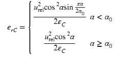
在Tabakoff and Grant模型中,冲蚀速率表示为:
原始Tabakoff and Grant模型中的一些常数仅适用于颗粒速度以ft/s形式指定,在CFX中对原始模型进行了修订:
The Tabakoff model typically returns an erosive wear with the dimensions milligrams of eroded material per gram of colliding particles. In CFX, this variable is converted into grams of eroded material per gram of colliding particles.
CFX中的变量与原始模型变量对照如下表所示:
| 变量 | 量纲 | CFX变量 |
|---|---|---|
| 无量纲 | K12常数 | |
| 无量纲 | ||
| [Velocity] | 参考速度1 | |
| [Velocity] | 参考速度2 | |
| [Velocity] | 参考速度3 | |
| [deg] | 最大冲蚀角 |
其中:
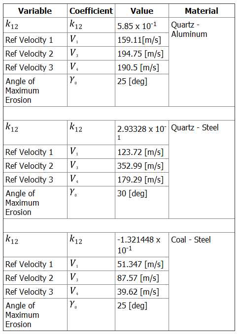
在CFX中使用Tabakoff模型需要5个参数,下面是一些材料冲蚀的参数,包括石英-铝、石英-钢、煤-钢的冲蚀数据。
[1] Ahlert, K. 1994. “Effects of particle impingement angle and surface wetting on solid particle erosion of AISI 1018 steel”, MS Thesis,where: University of Tulsa, USA.
[2] McLaury, B.S., Shirazi, S.A., Shadley, J.R., and Rybicki, E.F. 1996. “Modeling erosion in chokes”, ASME FED conference, 236(1), pp. 773–781.
[3] Haugen, K., Kvernvold, O., Ronold, A., and Sandberg, R. 1995. “Sand erosion of wear-resistant materials: Erosion in choke valves”, Wear, 186-187, pp. 179–188.
[4] Haugen, K., Kvernvold, O., Ronold, A., and Sandberg, R. 1995. “Sand erosion of wear-resistant materials: Erosion in choke valves”, Wear, 186-187, pp. 179–188.
[5] Neilson, J.H., and Gilchrist, A. 1968. “Erosion by a stream of solid particles”, Wear, 11, pp.111–122.
[6] Wallace, M.S., Peters, J.S., Scanlon, T.J., Dempster, W.M., McCulloch, S., and Ogilvie, J.B.2000. “CFD-based erosion modeling of multi-orifice choke valves”, ASME, Paper FEDSM2000-11244.
[7] Oka, Y.I, Okamura, K., and Yoshida, T. 2005. “Practical estimation of erosion damage caused by solid particle impact. Part 1: Effect of impact parameters on a predictive equation”, Wear, 259, pp. 95–101.
[8] Oka, Y.I., and Yoshida, T. 2005. “Practical estimation of erosion damage caused by solid particle impact. Part 2: Mechanical properties of materials directly associated with erosion damage”, Wear, 259, pp. 102–109.
[9] Archard, J. F., and Hirst, W. 1956. “The wear of metals under unlubricated conditions”,Proceedings of the Royals Society of London. Series A, Mathematical and Physical Sciences. 236(1206), pp 397-410.
[10] J. K. Edwards, B. S. McLaury, and S. A.Shirazi. “Evaluation of Alternative Pipe Bend Fittings in Erosive Service”. In Proceedings of ASME FEDSM’00: ASME 2000 Fluids Engineering Division Summer Meeting, Boston, MA. June 2000.
[11] I. Finnie. “Erosion of Surfaces by Solid Particles”. Wear. 3. 87–103. 1960.
[12] B. S. McLaury, J. Wang, S. A. Shirazi, J. R. Shadley, and E. F. Rybicki. “Solid Particle Erosion in Long Radius Elbows and Straight Pipes”. SPE Annual Technical Conference and Exhibition, II Production Operations and Engineering/General, San Antonio, Texas. SPE Paper 38842 October 1997.
[13] J. K. Edwards, B. S. McLaury, and S. A. Shirazi. “Supplementing a CFD Code with Erosion Prediction Capabilities”. In Proceedings of ASME FEDSM’98: ASME 1998 Fluids Engineering Division Summer Meeting, Washington DC. June 1998.
[14] L. Nokleberg and T. Sontvedt. “Erosion of Oil and Gas Industry Choke Valves Using Computational Fluid Dynamics and Experiment”. International Journal of Heat and Fluid Flow. 636–643. 1998.
[15] K. Haugen, O. Kvernvold, A. Ronald, and R. Sandberg. “Sand Erosion of Wear-resistant Materials: Erosion in Choke Valves.Wear”. 186-187. 179–188. 1995.
[16] M. M. Salama and E. S. Venkatesh. “Evaluation of api rp14e erosional velocity limitations for offshore gas wells”. In OTC Conference, Houston, TX. 371–376. May 1983.
[17]Hutchings, I.M.,“Mechanical and metallurgical aspects of the erosion of metals”,Proc. Conf. on Corrosion-Erosion of Coal Conversion System Materials, NACE (1979) 393.
[18]Dosanjh, S., and Humphrey, J.A.C.,“The influence of turbulence C on erosion by a particle laden fluid jet, Wear”,V.102, 1985, pp. 309-330.
标签:
原文地址:http://www.cnblogs.com/LSCAX/p/5324255.html