标签:des style blog http color os strong io
A method, apparatus, and computer usable program code for logical partitioning and virtualization in heterogeneous computer architecture. In one illustrative embodiment, a portion of a first set of processors of a first type is allocated to a partition in a heterogeneous logically partitioned system and a portion of a second set of processors of a second type is allocated to the partition.
The present application generally relates to an improved data processing system and in particular to a method and apparatus for managing a data processing system. Still more particularly, the present invention relates to a computer implemented method, apparatus, and computer usable program code for logical partitioning and virtualization in a data processing system.
In modern processor architectures, management of computer systems is a significant part of the total cost of ownership. A preferred solution to this challenge has been the use of hypervisors. A hypervisor is a scheme for allowing multiple operating systems to run on a computer system at the same time. A hypervisor may be implemented as a software layer that divides a system into multiple logical partitions that are able to execute independent operating systems. Because of these attractive attributes, including high security by separating independent workloads, ease of management, and so forth, the use of hypervisors has been an attractive solution for server system consolidation.
Currently, logical partitioning (LPAR) has been used to divide a single system into multiple partitions, a partition consisting of a subset of a set of similar processors. LPAR is a system architecture approach that promises to revolutionize corporate information technology (IT) infrastructures by enabling the capability to virtualize hardware resources that can be shared by multiple independent operating environments. Dynamic LPAR is an LPAR in which the resources of a system may be dynamically redefined during operation of the system. Virtualization of a system means that the system has the ability to simulate the availability of hardware that may not be present in sufficient amount or at all. Virtualization uses the available physical resources as a shared pool to emulate missing physical resources. Originally developed for mainframe computers, LPAR allows the division of a single server into several completely independent virtual servers or logical partitions. LPAR on eServer? i5 is supported by i5/OS? and AIX? 5L?, which are operating systems available from International Business Machines Corporation (IBM), and by the Linux? operating system available from one or more Linux distributors.
Since its introduction, LPAR used on the iseries? and now eServer i5 has re-energized server consolidation and information technology cost optimization strategies. Today, many IT users have successfully deployed LPAR to achieve quick consolidation of multiple workload environments, time zones, and footprints within a single or fewer iSeries? or eServer? i5 systems. These users have taken advantage of LPAR to benefit from the growing industry trend and the desire to optimize information technology investments and resource virtualization through consolidation of hardware, software, networks, data centers, and, more importantly, skills.
The innovations on virtualization of hardware resources continues to benefit both iSeries? and pSeries? clients. Introduced first on the eServer i5, the IBM Virtualization Engine system extends innovations such as micro-partitioning? to AIX? 5L?, automatic processor balancing with uncapped processor partitioning, and further exploiting virtual input/output (I/O) capabilities. A description of a state of the art dynamic logical partitioning system can be found in Jann et al, Dynamic Reconfiguration: Basic Building Blocks for Autonomic Computing on IBM pSeries Servers, IBM SYSTEMS JOURNAL, VOL 42, NO 1, 2003.
The exemplary embodiments described herein recognize the disadvantages of the prior art and provide a method, apparatus, and computer usable program code for logical partitioning and virtualization in heterogeneous computer architecture. In one illustrative embodiment, a portion of a first set of processors of a first type is allocated to a partition in a logically partitioned heterogeneous processor system and a portion of a second set of processors of a second type is allocated to the partition.
In another illustrative embodiment, the first set of processors comprises a single processor of the first type. In allocating a portion of the first set of processors of the first type to a partition, a time-shared portion of the single processor of the first type is allocated to the partition.
An operating system may be booted in the partition. Boot parameters may be read to determine if a number of processors available in the second set of processors. Responsive to a reconfiguration event, a portion of the first set of processors may be reallocated to the partition and a portion of the second set of processors may be reallocated to the partition. Responsive to a request to allocate a processor of the second type from the operating system, an additional processor of the second type may be allocated to the partition.
The heterogeneous architecture may be a Cell Broadband Engine (BE) architecture. The first set of processors may take the form of a set of Power Processor Elements (PPE) and the second set of processors is a set of Synergistic Processor Elements (SPE).
In one exemplary embodiment, a logical partition identifier may be assigned to a given SPE to associate with a partition and writing the assigned logical partition identifier to at least one configuration register associated with the given SPE. In another exemplary embodiment, an exception may be routed to a PPE in an internal interrupt controller based on the logical partition identifier.
In a further illustrative embodiment, the partition is a first partition and a second portion of the first set of processors of the first type is allocated to a second partition and a second portion of the second set of processors of the second type is allocated to the second partition. In an exemplary embodiment, the first partition is an application partition or a gaming partition. In another exemplary embodiment, the second partition is a network partition, a security partition or a media recording partition.
A data processing system may include a first set of processors of a first type, a second set of processors of a second type, and partition management software. The partition management software allocates a portion of the first set of processors to a partition in a heterogeneous logically partitioned system and allocates a portion of the second set of processors to the partition.
In other exemplary embodiments, the data processing system performs various ones of the operations outlined above with regard to the method in the illustrative embodiments.
In another illustrative embodiment, a computer program product for logical partitioning and virtualization in a heterogeneous computer architecture comprises a computer usable medium having computer usable program code embodied therein. The computer usable program code is configured to allocate a portion of a first set of processors of a first type to a partition in a heterogeneous logically partitioned system, and to allocate a portion of a second set of processors of a second type to the partition.
In other exemplary embodiments, the computer program product comprises computer usable program code for performing various ones of the operations outlined above with regard to the method in the illustrative embodiments.
With reference now to the drawings,?FIG. 1?illustrates a prior art computer system including a hypervisor and is capable of supporting multiple operating systems. The computer system includes hardware?100. In these illustrative embodiments, hardware?100?contains components found in computer systems. In these examples, the processor architecture of hardware?100?is implemented using Power Archtecture? from IBM.
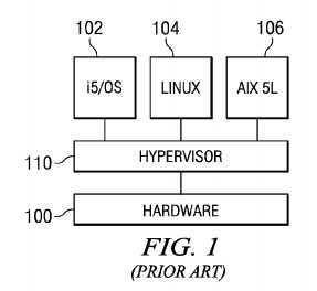
Hardware?100?is partitioned to run operating systems?102,?104, and?106. In the depicted example, operating system?102?is an i5/OS? operating system, operating system?104?is a Linux? operating system, and operating system?106is an AIX? 5L? operating system. In various other implementations, operating systems?102,?104, and?106?may be multiple copies of a single operating system or multiple heterogeneous operating systems running simultaneously on hardware?100.
The operating systems are designed to interface with a partition management software, such as hypervisor?110. Of course, other types of operating systems may be used depending on the particular implementation. Hypervisor software is an example of partition management software that may be used to implement partition management software and is available from International Business Machines Corporation. In this example, hypervisor?110?is in the form of firmware. Firmware is "software" stored in a memory chip that holds its content without electrical power, such as, for example, read-only memory (ROM), programmable ROM (PROM), erasable programmable ROM (EPROM), electrically erasable programmable ROM (EEPROM), and nonvolatile random access memory (nonvolatile RAM).
Hardware?100?may include, for example, a processor, a system memory unit, an input/output (I/O) adapter, and one or more storage units. Hypervisor?110?may assign each of the processors, memory units, storage units, and I/O adapters to one of the multiple partitions. Each of these partitions corresponds to one of operating systems?102,?104, and?106.
Innovations in the server arena have not included support for lower-end systems. Desktop computer systems are typically only able to run a single operating system, or emulate one operating system under a second operating system, such as provided by VirtualPC? or VMware? applications emulating a first operating system on a second operating system. Emulating a first operating system on a second operating system has undesirable aspects relating to performance, system stability, and maintenance.
Currently Available Heterogeneous Processor systems used in computer systems have been characterized by a collection of fixed function accelerators and special purpose processing units, but do not implement a common architecture. With such processor systems, usually a single operating system manages the main processor, while accelerators and special purpose processing units typically are allocated to fixed acceleration tasks, such as global system mobile (GSM) communications speech encode and decode, or protocol and signal processing. Currently available heterogeneous processor systems have been limited to running a single operating system.
FIG. 2?is a block diagram illustrating an example of an advanced prior art heterogeneous processor system. A heterogeneous processor system is a plurality of processors in which at least two types of processors are present. These processors may be on different chips, or some or all of the processors may be located on the same chip.
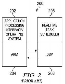
In this example, the heterogeneous processor system includes a general purpose processor and a second special purpose processor. As discussed, the general purpose processor is Advanced RISC (ARM) processor?204, the special purpose processor is digital signal processor (DSP)?208. ARM is a family of RISC-based microprocessors and microcontrollers from ARM Inc.
ARM processor?204?runs application-oriented operating system?202, and DSP?208?runs real-time task scheduler?206. In this example, the known processor system shown in?FIG. 2?provides the ability to run independent operating systems on a collection of processors, but not multiple operating systems wherein each operating system manages both processors of a first and a second type. This solution, however, does not offer integrated management of applications, a consistent system view with a common memory hierarchy or optimized scheduling of applications across a heterogeneous processor system.
The illustrative embodiments recognize that the design of integrated management, virtualization, and logical partitioning of heterogeneous multi-core processors while providing an integrated system view has thus far eluded those skilled in the art. The depicted embodiments recognize a need to provide virtualization and logical partitioning in a computer system having a heterogeneous multi-core processor. What is furthermore desirable is to provide a consistent view of the computer system with dynamic management capabilities, while offering an integrated system view encompassing all processing elements in a computer system. The embodiments also recognize that it is desirable to have the ability to partition a multi-core processor consisting of a first and second processor element type into multiple subsystems, each of which having optionally both element types within their respective partitions. A processor core is a processing unit on a chip. A processor core typically includes an instruction unit and an execution unit. A processor core also may include other components, such as a cache. Multiple processor cores may be placed on a chip to form a multi-core processor.
In another embodiment, a hypervisor offering these features is adapted to execute on a processor architecture consisting of a first type of processor elements optimized for general-purpose processing, and a second type of processor elements optimized for data-processing. In another embodiment, the hypervisor understands the heterogeneous nature of a heterogeneous processor system in which only a first type of processor elements can perform certain tasks. With this type of environment, the hypervisor schedules at least one processor of the first type in response to a request to perform such task in response to actions by a second type of processor. An example of such a task is servicing a page fault.
In an "always-on" small office/home office environment, or in private homes, hypervisors may offer attractive properties, such as securely separating applications from other functions like network functions related to data and application download, digital personal video recorder, and digital media downloads. In another example of hypervisor functions, a first partition can execute an application assuming full control of a partition, while in another partition, network services and the like may be operating with a specific local network service requirements. The second partition may, for example, execute software or drivers to act as a bridge between a fully controlling system, such as the first partition, not having awareness of different network topologies and the local network.
FIG. 3?is a block diagram illustrating the use of a hypervisor in a user application environment in accordance with an illustrative embodiment. A computer system runs under the control of hypervisor?300?and has at least two partitions. In the depicted example, one partition is user partition?310?and is directed at a user operating system or other user applications. These applications include, but are not limited to, a desktop operating system, a video display system, and a game application.

In one embodiment, user partition?310?is fixed, and not aware of specific configuration, I/O, and network characteristics. These other services are provided by at least one other partition.
For example, network partition?320, is directed to providing at least one service to user partition?310. In one embodiment, network partition?320?provides network services via network?330?and is aware of specific network access medium and topology requirements. In an exemplary embodiment, this service may be provided by network partition?320?running a Linux? operating system. In another embodiment, network partition?320?may execute an operating system provided by a network service provider.
Additional partitions may be provided, such as those directed to other services. Recording a video stream to a storage medium, in which the video stream optionally being received from a broadband network or a broadcast channel, is an example of a service.
Referring now to?FIG. 4, a block diagram is shown illustrating an exemplary Cell Broadband Engine (BE) chip in accordance with the exemplary embodiment.?FIG. 4?is provided as an exemplary diagram of a data processing environment in which aspects of the exemplary embodiments may be implemented. It should be appreciated that?FIG. 4?is only exemplary and is not intended to assert or imply any limitation with regard to the environments in which different embodiments may be implemented. Many modifications to the depicted environment may be made without departing from the spirit and scope of the illustrative embodiments.
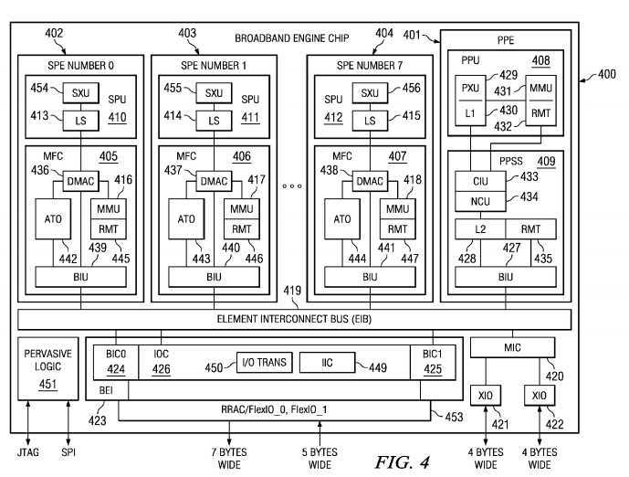
Cell BE chip?400?is an example of a heterogeneous processor system using a single-chip multi-core processor. This illustrative embodiment is directed toward distributed processing targeted for media-rich applications such as game consoles, desktop systems, and servers.
Cell BE chip?400?may be logically separated into the following functional components: Power PC? processor element (PPE)401, synergistic processor units (SPEs)?402,?403, and?404, and memory flow controllers (MFCs)?405,?406, and?407. Although synergistic processor elements (SPEs)?402,?403, and?404?and PPE?401?are shown by example, any type of processor element may be supported. Exemplary Cell BE chip?400?implementation includes one PPE?401?and eight SPEs, although?FIG. 4?shows only three SPEs?402,?403, and?404. The SPE of a CELL Processor is a first implementation of a new processor architecture designed to accelerate media and data streaming workloads.
Cell BE chip?400?may be a system-on-a-chip such that each of the elements depicted in?FIG. 4?may be provided on a single microprocessor chip. Moreover, Cell BE chip?400?is a heterogeneous processing environment in which each of SPUs?410,411, and?412?may receive different instructions from each of the other SPUs in the system. Moreover, the instruction set for SPUs?410,?411, and?412?is different from that of Power PC? processor unit (PPU)?408, e.g., PPU?408?may execute Reduced Instruction Set Computer (RISC) based instructions in the Power? architecture while SPUs?410,?411, and?412execute vectorized instructions.
Each SPE includes one SPU?410,?411, or?412?with its own local store (LS) area?413,?414, or?415?and a dedicated MFC405,?406, or?407?that has an associated memory management unit (MMU)?416,?417, or?418?to hold and process memory protection and access permission information. Once again, although SPUs are shown by example, any type of processor unit may be supported. Additionally, Cell BE chip?400?implements element interconnect bus (EIB)?419?and other I/O structures to facilitate on-chip and external data flow.
EIB?419?serves as the primary on-chip bus for PPE?401?and SPEs?402,?403, and?404. In addition, EIB?419?interfaces to other on-chip interface controllers that are dedicated to off-chip accesses. The on-chip interface controllers include the memory interface controller (MIC)?420, which provides two extreme data rate I/O (XIO) memory channels?421?and?422, and Cell BE interface unit (BEI)?423, which provides two high-speed external I/O channels and the internal interrupt control for Cell BE?400. BEI?423?is implemented as bus interface controllers (BICs, labeled BIC0?& BIC1)?424?and?425?and I/O interface controller (IOC)?426. The two high-speed external I/O channels connected to a polarity of Redwood Rambus? Asic Cell (RRAC) interfaces providing the flexible input and output (FlexIO_0?& FlexIO_1)?453?for the Cell BE?400.
Each SPU?410,?411, or?412?has a corresponding LS area?413,?414, or?415?and synergistic execution units (SXU)?454,?455, or?456. Each individual SPU?410,?411, or?412?can execute instructions (including data load and store operations) only from within its associated LS area?413,?414, or?415. For this reason, MFC direct memory access (DMA) operations via SPU‘s410,?411, and?412?dedicated MFCs?405,?406, and?407?perform all required data transfers to or from storage elsewhere in a system.
A program running on SPU?410,?411, or?412?only references its own LS area?413,?414, or?415?using a LS address. However, each SPU‘s LS area?413,?414, or?415?is also assigned a real address (RA) within the overall system‘s memory map. The RA is the address for which a device will respond. In the Power PC?, an application refers to a memory location (or device) by an effective address (EA), which is then mapped into a virtual address (VA) for the memory location (or device) which is then mapped into the RA. The EA is the address used by an application to reference memory and/or a device. This mapping allows an operating system to allocate more memory than is physically in the system (i.e. the term virtual memory referenced by a VA). A memory map is a listing of all the devices (including memory) in the system and their corresponding RA. The memory map is a map of the real address space which identifies the RA for which a device or memory will respond.
This allows privileged software to map a LS area to the EA of a process to facilitate direct memory access transfers between the LS of one SPU and the LS area of another SPU. PPE?401?may also directly access any SPU‘s LS area using an EA. In the Power PC? there are three states (problem, privileged, and hypervisor). Privileged software is software that is running in either the privileged or hypervisor states. These states have different access privileges. For example, privileged software may have access to the data structures register for mapping real memory into the EA of an application. Problem state is the state the processor is usually in when running an application and usually is prohibited from accessing system management resources (such as the data structures for mapping real memory).
The MFC DMA data commands always include one LS address and one EA. DMA commands copy memory from one location to another. In this case, an MFC DMA command copies data between an EA and a LS address. The LS address directly addresses LS area?413,?414, or?415?of associated SPU?410,?411, or?412?corresponding to the MFC command queues. Command queues are queues of MFC commands. There is one queue to hold commands from the SPU and one queue to hold commands from the PXU or other devices. However, the EA may be arranged or mapped to access any other memory storage area in the system, including LS areas?413,?414, and?415?of the other SPEs?402,?403, and?404.
Main storage (not shown) is shared by PPU?408, PPE?401, SPEs?402,?403, and?404, and I/O devices (not shown) in a system, such as the system shown in?FIG. 2. All information held in main memory is visible to all processors and devices in the system. Programs reference main memory using an EA. Since the MFC proxy command queue, control, and status facilities have RAs and the RA is mapped using an EA, it is possible for a power processor element to initiate DMA operations, using an EA between the main storage and local storage of the associated SPEs?402,?403, and?404.
As an example, when a program running on SPU?410,?411, or?412?needs to access main memory, the SPU program generates and places a DMA command, having an appropriate EA and LS address, into its MFC?405,?406, or?407command queue. After the command is placed into the queue by the SPU program, MFC?405,?406, or?407?executes the command and transfers the required data between the LS area and main memory. MFC?405,?406, or?407?provides a second proxy command queue for commands generated by other devices, such as PPE?401. The MFC proxy command queue is typically used to store a program in local storage prior to starting the SPU. MFC proxy commands can also be used for context store operations.
The EA address provides the MFC with an address which can be translated into a RA by the MMU. The translation process allows for virtualization of system memory and access protection of memory and devices in the real address space. Since LS areas are mapped into the real address space, the EA can also address all the SPU LS areas.
PPE?401?on Cell BE chip?400?consists of 64-bit PPU?408?and Power PC? storage subsystem (PPSS)?409. PPU?408contains processor execution unit (PXU)?429, level 1 (L1) cache?430, MMU?431?and replacement management table (RMT)432. PPSS?409?consists of cacheable interface unit (CIU)?433, non-cacheable unit (NCU)?434, level 2 (L2) cache?428, RMT435?and bus interface unit (BIU)?427. BIU?427?connects PPSS?409?to EIB?419.
SPU?410,?411, or?412?and MFCs?405,?406, and?407?communicate with each other through unidireactional channels that have capacity. Channels are essentially a FIFO which are accessed using one of 34 SPU instructions; read channel (RDCH), write channel (WRCH), and read channel count (RDCHCNT). The RDCHCNT returns the amount of information in the channel. The capacity is the depth of the FIFO. The channels transport data to and from MFCs?405,?406, and?407, SPUs?410,?411, and?412. BIUs?439,?440, and?441?connect MFCs?405,?406, and?407?to EIB?419.
MFCs?405,?406, and?407?provide two main functions for SPUs?410,?411, and?412. MFCs?405,?406, and?407?move data between SPUs?410,?411, or?412, LS area?413,?414, or?415, and main memory. Additionally, MFCs?405,?406, and?407provide synchronization facilities between SPUs?410,?411, and?412?and other devices in the system.
MFCs?405,?406, and?407?implementation has four functional units: direct memory access controllers (DMACs)?436,?437, and?438, MMUs?416,?417, and?418, atomic units (ATOs)?442,?443, and?444, RMTs?445,?446, and?447, and BIUs?439,?440, and?441. DMACs?436,?437, and?438?maintain and process MFC command queues (MFC CMDQs) (not shown), which consist of a MFC SPU command queue (MFC SPUQ) and a MFC proxy command queue (MFC PrxyQ). The sixteen-entry, MFC SPUQ handles MFC commands received from the SPU channel interface. The eight-entry, MFC PrxyQ processes MFC commands coming from other devices, such as PPE?401?or SPEs?402,?403, and?404, through memory mapped input and output (MMIO) load and store operations. A typical direct memory access command moves data between LS area413,?414, or?415?and the main memory. The EA parameter of the MFC DMA command is used to address the main storage, including main memory, local storage, and all devices having a RA. The local storage parameter of the MFC DMA command is used to address the associated local storage.
In a virtual mode, MMUs?416,?417, and?418?provide the address translation and memory protection facilities to handle the EA translation request from DMACs?436,?437, and?438?and send back the translated address. Each SPE‘s MMU maintains a segment lookaside buffer (SLB) and a translation lookaside buffer (TLB). The SLB translates an EA to a VA and the TLB translates the VA coming out of the SLB to a RA. The EA is used by an application and is usually a 32- or 64-bit address. Different application or multiple copies of an application may use the same EA to reference different storage locations (for example, two copies of an application each using the same EA, will need two different physical memory locations.) To accomplish this, the EA is first translated into a much larger VA space which is common for all applications running under the operating system. The EA to VA translation is performed by the SLB. The VA is then translated into a RA using the TLB, which is a cache of the page table or the mapping table containing the VA to RA mappings. This table is maintained by the operating system.
ATOs?442,?443, and?444?provide the level of data caching necessary for maintaining synchronization with other processing units in the system. Atomic direct memory access commands provide the means for the synergist processor elements to perform synchronization with other units.
The main function of BIUs?439,?440, and?441?is to provide SPEs?402,?403, and?404?with an interface to the EIB. EIB?419provides a communication path between all of the processor cores on Cell BE chip?400?and the external interface controllers attached to EIB?419.
MIC?420?provides an interface between EIB?419?and one or two of XIOs?421?and?422. Extreme data rate (XDR?) dynamic random access memory (DRAM) is a high-speed, highly serial memory provided by Rambus?. A macro provided by Rambus accesses the extreme data rate dynamic random access memory, referred to in this document as XIOs?421?and422.
MIC?420?is only a slave on EIB?419. MIC?420?acknowledges commands in its configured address range(s), corresponding to the memory in the supported hubs.
BICs?424?and?425?manage data transfer on and off the chip from EIB?419?to either of two external devices. BICs?424?and425?may exchange non-coherent traffic with an I/O device, or it can extend EIB?419?to another device, which could even be another Cell BE chip. When used to extend EIB?419, the bus protocol maintains coherency between caches in the Cell BE chip?400?and the caches in the attached external device, which could be another Cell BE chip.
IOC?426?handles commands that originate in an I/O interface device and that are destined for the coherent EIB?419. An I/O interface device may be any device that attaches to an I/O interface such as an I/O bridge chip that attaches multiple I/O devices or another Cell BE chip?400?that is accessed in a non-coherent manner. IOC?426?also intercepts accesses on EIB419?that are destined to memory-mapped registers that reside in or behind an I/O bridge chip or non-coherent Cell BE chip400, and routes them to the proper I/O interface. IOC?426?also includes internal interrupt controller (IIC)?449?and I/O address translation unit (I/O Trans)?450.
Pervasive logic?451?is a controller that provides the clock management, test features, and power-on sequence for the Cell BE chip?400. Pervasive logic may provide the thermal management system for the processor. Pervasive logic contains a connection to other devices in the system through a Joint Test Action Group (JTAG) or Serial Peripheral Interface (SPI) interface, which are commonly known in the art.
Although specific examples of how the different components may be implemented have been provided, this is not meant to limit the architecture in which the aspects of the illustrative embodiments may be used. The aspects of the illustrative embodiments may be used with any multi-core processor system.
FIG. 5?illustrates an example of partitioning a heterogeneous processor system in accordance with an illustrative embodiment. In the depicted example, Cell BE chip?500?is an example of a heterogeneous processor system. The hypervisor (not shown) may be software running on PPE?502?and?504, for example. In Cell BE chip?500, PPE?502?and a first set of SPEs, SPEs?506?and?508, are allocated to a first partition, partition?510. PPE?504?and a second set of SPEs, SPEs?512-522, are allocated to a second partition, partition?524.
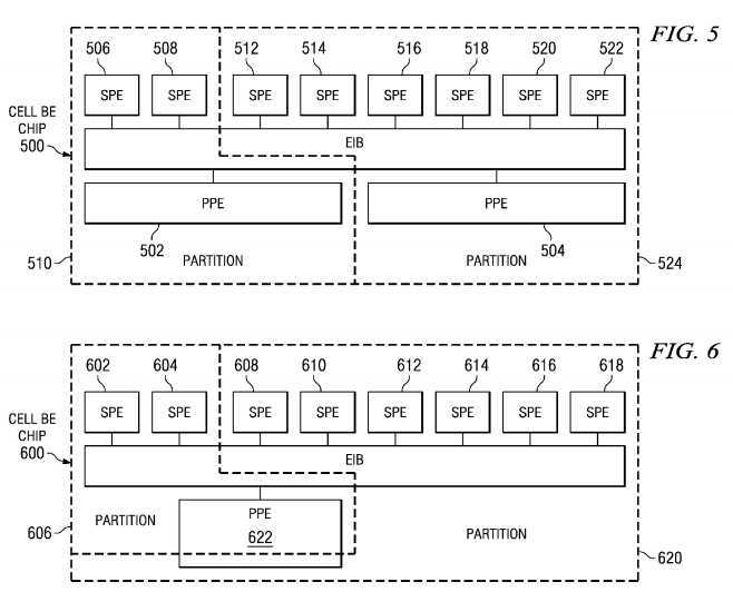
Referring to?FIG. 6, partitioning of a heterogeneous processor system with time-sharing of a processor is depicted in accordance with an illustrative embodiment. In this example, Cell BE chip?600?is virtualized and shared between partitions. In the depicted example, a hypervisor (not shown) provides a fixed allocation of SPEs?602?and?604?to partition?606, and SPEs?608-618?to partition?620. The two partitions share a portion of PPE?622?in a time-shared fashion. Time-sharing occurs, in this example, because processing time or cycles for PPE?622?is shared between partition?606?and partition?620.
Those of ordinary skill in the art will understand that another partition consisting only of a PPE, or multiples, or fractions thereof are also possible as an example of another illustrative configuration. In some systems, partitions consisting wholly of a second set of computing elements are supported by the illustrative embodiments. Referring now to an embodiment based on the Cell BE chip, a fraction of a first PPE is used to ensure certain system services provided by the PPE, as discussed below with reference to?FIG. 11.
In another embodiment, a partition consisting of a dedicated function executing exclusively on an SPE may be supported. In another embodiment, at least one SPE is assigned to the hypervisor to implement hypervisor support tasks and/or to emulate a virtual device provided by the hypervisor to at least one logical partition. Some examples of hypervisor support tasks include performing memory copy operations or managing virtualized I/O operations.
Depending on the implementation, a hypervisor may support different strategies for resource allocation and management with respect to a first set and second set of processor elements. For example, in an exemplary embodiment based on the Cell BE chip, a hypervisor design may use time-sharing for PPEs with an emphasis on flexibility given a comparatively lower context switch cost and a low number of PPEs being available. The hypervisor may implement space sharing for SPEs, with an emphasis on computing performance, and given a comparatively higher context switch cost and a high number of SPEs in system. Time-sharing is when a processor is virtualized by providing time slices to different virtual processors to provision multiple virtual processors. In the depicted example, the PPE is time-shared between partitions. Space sharing is where multiple processors are provisioned in hardware and they are allocated to different virtual processors in a specific partition, i.e., the resources are shared by allocating a set of resources to a specific virtual machine. In the depicted example, the SPEs are space shared.
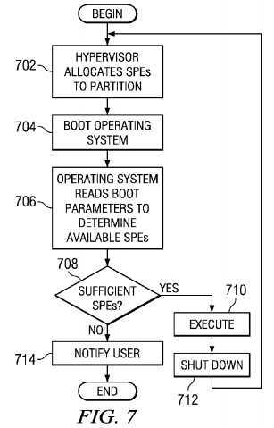
FIG. 7?is a flowchart of a process for the operation of a heterogeneous processor system with space sharing of SPEs, wherein reboot of a partition occurs when partition parameters changed, in accordance with an illustrative embodiment. It will be understood that each step of the flowchart illustrations, and combinations of steps in the flowchart illustrations, can be implemented by computer program instructions. These computer program instructions may be provided to a processor or other programmable data processing apparatus to produce a machine, such that the instructions which execute on the processor or other programmable data processing apparatus create means for implementing the functions specified in the flowchart step or steps.
These computer program instructions may also be stored in a computer-readable memory, transmission medium, or storage medium that can direct a processor or other programmable data processing apparatus to function in a particular manner, such that the instructions stored in the computer-readable memory, transmission medium, or storage medium produce an article of manufacture including instruction means which implement the functions specified in the flowchart step or steps.
Accordingly, steps of the flowchart illustrations support combinations of means for performing the specified functions, combinations of steps for performing the specified functions and computer usable program code for performing the specified functions. It will also be understood that each step of the flowchart illustrations, and combinations of steps in the flowchart illustrations, can be implemented by special purpose hardware-based computer systems which perform the specified functions or steps, or by combinations of special purpose hardware and computer instructions.
With particular reference to?FIG. 7, the hypervisor allocates SPEs to a partition (step?702). Then, the hypervisor boots an operating system for the partition (step?704). The operating system reads the boot parameters to determine available SPEs (step?706).
In allocating an SPE to a partition, the hypervisor allocates an SPE in one embodiment by programming at least one register to indicate the logical partition identifier (LPID) of the partition to which the SPE is allocated. The hypervisor assigns a logical partition identifier to a SPE to be associated with a partition and writes the assigned logical partition identifier to at least one configuration register associated with the given SPE. In the depicted example, the LPID is used to identify the target partition for exceptions generated by the SPE. In another example, the LPID in an SPE is used to locate and identify page table information associated with the partition.
Referring now to the allocation of SPEs, in one embodiment the hypervisor allocates, at least one SPE to itself. In another embodiment, the hypervisor uses the SPU to perform hypervisor acceleration tasks. In yet another embodiment, the hypervisor uses at least one SPE to perform acceleration tasks. The hypervisor also uses an SPE to provide a variety of security and digital rights management (DRM) functions in other embodiments.
The operating system determines whether sufficient SPEs are available (step?708). If sufficient SPEs are available, the operating system executes (step?710). In step?710, the operating system runs to perform operating system tasks and executes applications until the partition is shut down. A partition is a virtual computer, and "system executes" in this case means the virtual system is in operation until terminated. When execution in the partition as described in step?710terminates, the partition shuts down (step?712) and the process returns to step?702?where the hypervisor allocates the SPEs to another partition. Turning back to step?708, if sufficient SPEs are not available, the operating system notifies the user (step?714) and the process ends. When the user is notified in step?714, the user may perform different actions. For example, the user may use another application, invoke the application and tell it to use fewer SPEs, or terminate another application and restart this application.
With respect to the creation of partitions, the hypervisor can support creation of partitions containing at least one PPE and one SPE, partitions containing only PPE processors, and partitions containing only SPE processors. In an illustrative embodiment, the hypervisor provides additional support functions to SPE-only partitions to provide at least basic system memory management functions.
FIG. 8?is a flowchart of a process for static partitioning of synergistic processor elements with partition reconfiguration in accordance with an illustrative embodiment.
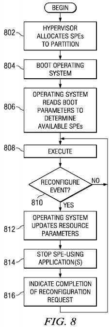
The hypervisor begins with the allocating of SPEs to the partition (step?802). The hypervisor then boots the operating system for the partition (step?804). The operating system reads the boot parameters to determine available SPEs (step806) and the system executes (step?808).
Next, the hypervisor determines whether a reconfigure event occurs (step?810). A reconfigure event is an event that requires reallocation of resources or the use of resources. This reallocation may include reallocating processor resources. A user can dynamically change the size of partitions. The hypervisor, in conjunction with system management software performs the reconfiguration. A reconfigure event may be caused, for example, by a reconfiguration request or a monitoring program that determines reconfiguration is needed. This reconfiguration occurs with automatic system management also known as "autonomic computing".
If a reconfigure event does not occur, the process returns to step?808?where the system executes. If a reconfigure event occurs in step?810, the operating system updates the resource parameters (step?812) and optionally stops one or more SPE-using applications to reconcile the number of the SPEs used with the SPEs available in the partition (step?814). The operating system updates the resource parameters to include an identification of the resources now assigned to the partition. For example, the update may include an identification of a new SPE assigned to the partition. The operating system indicates completion of reconfiguration request via a handshake with the hypervisor (step?816). Thereafter, the process returns to step?808?where the system executes.
FIG. 9?is a flowchart of a process for operation of dynamic time-shared partitioning with gang scheduling in accordance with an illustrative embodiment. In this example, the SPEs are virtualized by the hypervisor and made available across several partitions.
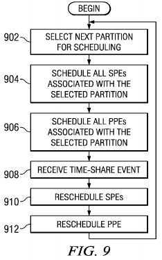
The process begins with the hypervisor selecting the next partition for scheduling (step?902). The hypervisor schedules all SPEs associated with the selected partition (step?904) and schedules all PPEs associated with the selected partition (step906). In steps?904?and?906, the hypervisor decides which processors should be assigned to that partition, and configures it appropriately. This configuration, for example, includes configuring memory management information, updating LPID and other LPAR configuration registers to reflect the membership in a specific logical partition, load registers and other data that represents an architected state (such as the local store content in the case of the SPE), and initiating execution as part of the selected LPAR at the entry point associated with the specific virtual processor of that LPAR. When an SPE is scheduled, the SPE starts to execute the program associated with the virtual SPE of the partition to which it is assigned.
The hypervisor receives a time-share event (step?908), reschedules the SPEs (step?910), and reschedules the PPEs (step912). The time-share event comes from a timer interrupt, or other interrupt associated with time keeping to share a physical processor between multiple virtual processors in these examples. A clock, implemented in chip or on system board, or otherwise integrated in system generates a time-share event in these examples. Thereafter, the process returns to step902?to select the next partition for scheduling.
In one embodiment, the operating system identifies a request to reduce resource usage, triggered by a "pseudo-exception" or other such hypervisor-to-operating system request functionality, delivered to an operating system that is equipped to handle said hypervisor requests. This example may involve time-sharing of SPEs until the resource profile of applications is reduced and may include shutting down or freezing an application. This example may involve the operating system handshaking with the hypervisor to indicate an SPE is available to remove.
In one embodiment, time-share events are indicated by a hypervisor decremeter (HDEC). This component provides the hypervisor an ability to determine the end of a time share allocated to a specific partition. In accordance with such an implementation, the HDEC register is set to a value corresponding to a time quatum allocated to a partition, and a next partition is scheduled when an HDEC decrementer exception is received.
FIG. 10?is a flowchart of a process for space partitioning with processor allocation in accordance with an illustrative embodiment. In this example, the hypervisor does not permanently assign SPEs to partitions. Instead, the operating system dynamically allocates the SPEs by issuing requests to the hypervisor to change or reconfigure the allocation.

The process begins with the application performing a system call requesting a SPE (step?1002). The operating system identifies whether an SPE is available (step?1004). The operating system allocates available SPEs (step?1006) and performs a hypervisor request to allocate the SPEs (step?1008).
The hypervisor allocates the SPEs (step?1010?and returns to the operating system (step?1012). Control to continue execution in step?1012. The operating system then returns to the application (step?1014). Thereafter, the application uses the SPE (step?1016), and process terminates. In step?1016, the application may send the SPE instructions to perform a calculation or other processing of data.
In the context of this application, an SPE is assigned to a computer program by configuring the associated memory flow controller within the SPE to indicate the assignment. As such, an SPU execution resource is assigned by assigning the SPE. In many instances, the terms "SPU" and "SPE" are used interchangeably.
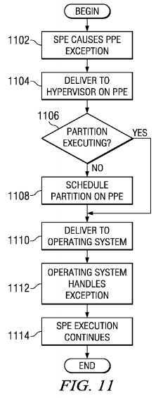
FIG. 11?is a flowchart of a process illustrating operation of on-demand hypervisor management of processor resources in accordance with an illustrative embodiment. The process beings with an SPE causing a PPE exception (step?1102). The SPE delivers the exception to the hypervisor on the PPE (step?1104). In one embodiment, SPE-originated exceptions are delivered to a PPE using an internal interrupt controller equipped to process external exception and interrupt events directed at a processor. When a page fault or other exception condition is detected, the condition is handled on the PPE. To accomplish this, the Cell BE Internal Interrupt Controller (IIC) delivers SPE exceptions. The depicted implementation has two IIC‘s for each PPE, corresponding to one per PPE thread. The IIC then delivers the exception to the PPE, where it is handled under the control of the Logical Partitioning Environment Selector (LPES).
In accordance with a first LPES setting, wherein the LPES is configured to a value of 0b01, the PPE delivers the interrupt to the hypervisor by putting the PPE into hypervisor mode and raising an exception. As a result, the interrupt goes directly to the hypervisor and the hypervisor interrogates the IIC.
In accordance with a second LPES setting, wherein the LPES is configured to a value of 0b11, the PPE delivers the interrupt to the operating system running in the current partition by putting the PPE into privileged operating system mode and raising an exception. The hypervisor expects the partition to perform an hcall query (H_XIRR) which causes the hypervisor to interrogate the IIC.
From that common point, the/any hypervisor then "routes" the interrupt to the appropriate partition by reflecting the interrupt to the partition‘s 0x500 vectored exception facility.
The second model requires cooperative operation between operating systems, by delivering exceptions not destined to the current partition to a hypervisor. In other configurations in accordance with an illustrative embodiment, an implementation can support determining whether an exception source and target have the same LPID identifier. Not all exceptions have associated partition identifiers, as some resources may be shared between multiple partitions. If the LPID identifiers match, the exception is delivered to the operating system. Otherwise, the exception is delivered to the hypervisor. When multiple PPEs are present, an implementation can select the target PPE based on partition membership information to increase the likelihood of delivering events to associated partitions.
Of course, other configurations are also possible in the scope of the embodiments, such as providing only a single exception delivery model without providing LPES-based configuration. Other determination steps and methods can also be practiced within the scope of the illustrative embodiments.
In some processor architectures, interrupts refer to internal events, while exceptions refer to external events. In these examples, both types of events are referenced, unless otherwise indicated by the context. Hence, in the context of the teachings contained herein, "interrupt" and "exception" are used interchangeably.
The hypervisor determines whether the partition associated with the exception-causing SPE is executing on the PPE (step1106). In step?1106, the hypervisor is scheduled on the PPE. When a virtual SPE wants to deliver an exception to a virtual PPE, this determination determines whether the physical PPE represents an appropriate virtual PPE. This determination is made because the PPE could be bound to another partition, and there may not be a PPE currently scheduled for this partition. In one embodiment, this check is performed by comparing a logical partition identifier (LPID) associated with the SPE raising the exception with the logical partition identifier of at least one PPE.
If the corresponding partition is not executing, the hypervisor schedules the partition on the PPE (step?1108) and delivers the exception to the operating system (step?1110). If a partition is executing on the PPE in step?1106, the process proceeds directly to step?1110?to deliver to the operating system. In one embodiment, the exception is delivered using a mediated external interrupt mechanism in accordance with the Power Architecture? specification.
Next, the operating system handles the exception (step?1112), and the operating system, or an application executing on the operating system handles the SPE exception. If SPE execution or memory flow controller (MFC) operation has been stopped in the SPE, execution is optionally restarted. The SPE execution then continues (step?1114). Thereafter, the process terminates.
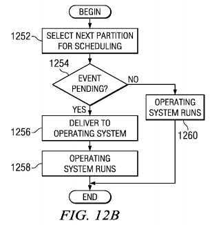
Referring now to?FIGS. 12A and 12B, in an alternative embodiment, if the partition associated with the SPE exception is not executing on a Cell BE chip, the hypervisor preserves exception information until the target partition of the SPE exception is scheduled on the Cell BE chip. An example of a partition not executing in the core is when an LPID of the exception-generating SPE does not match the LPID of the PPE. In accordance with this decision, the cost of context switching is reduced, by reducing the number of context switch events, at the cost of delaying response time to exceptions.
FIGS. 12A and 12B?show alternate embodiments of handling processor-generated events when no principal processor is associated with the partition generating the event. More particularly, with reference to?FIG. 12A, the process begins with the SPE causes a PPE exception (step?1202). The SPE delivers the hypervisor to the PPE (step?1204).
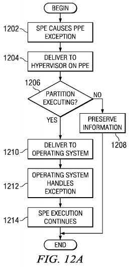
The hypervisor determines whether the partition corresponding to the partition of the exception-causing SPU is executing on the Cell BE chip (step?1206). If the partition is not executing on the core, the hypervisor preserves exception information until the partition is dispatched (step?1208), and the process terminates. If the partition is executing the Cell BE chip in step1206, the hypervisor delivers the exception to the operating system (step?1210). Next, the operating system handles the exception (step?1212), and the SPE execution continues (step?1214) with the process terminating thereafter.
Turning to?FIG. 12B, the process begins with the hypervisor selecting the next partition for scheduling (step?1252). The hypervisor determines whether an event is pending (step?1254). If an event is pending, the hypervisor delivers the exception to the operating system (step?1256), and the operating system runs (step?1258). In step?1258, the operating system continues to run and processes the exception. Thereafter, the process terminates. If an event is not pending in step?1254, the operating system runs (step?1260), and the process terminates.
In another embodiment, a dynamic determination is made whether to deliver the exception immediately, or in a delayed manner. According to such embodiments, real-time partitions are preferably not interrupted to schedule an alternate partition to deliver an exception. In another aspect of dynamic decisions, exceptions requiring real-time response cause their target partition to be scheduled on at least one Power Architecture? core and are delivered immediately. Those skilled in the art will understand the use of other dynamic criteria.
Although the depicted examples use a hypervisor to provide features for the different embodiments, this particular type of partition management software was chose merely to illustrate one possible implementation. These depicted features may be implemented in any type of partition management software.
Although the depicted examples have been explained in the context of a Cell BE chip, other embodiments can be implemented using other heterogeneous architectures, wherein other cores are taking the place of a first PPE and a second SPE.
Thus, the illustrative embodiment provides a mechanism for logical partitioning and virtualization in a heterogeneous architecture. The embodiments provide a consistent view of the system with dynamic management capabilities. The illustrative embodiments offer an integrated system view that encompasses all processing elements in a system. A hypervisor may partition a heterogeneous processor system into multiple subsystems, each of which having optionally multiple processor element types within the respective partitions.
SRC=https://www.google.com/patents/US20080028408
Logical partitioning and virtualization in a heterogeneous architecture,布布扣,bubuko.com
Logical partitioning and virtualization in a heterogeneous architecture
标签:des style blog http color os strong io
原文地址:http://www.cnblogs.com/coryxie/p/3891127.html