标签:
在写之前,首先给大家介绍一个学习shader的网站shadertoy。最近因为做项目要显示向量场,学习了一些GLSL着色语言的知识。虽然GLSL本身不难学,但对一个初学者来说,没有强大的数学和图形学功底,基本很难想写出好的shader。shadertoy提供了很多shader的例子,大家可以直接借鉴这些例子,编辑自己的shader。
向量场可视化
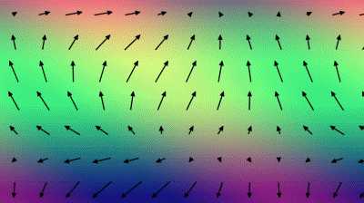
绘制向量场的方法有很多种,常见的有LIC(线积分卷积)纹理流场和箭头向量场(详细的介绍见:http://www.zhanpingliu.org/Research/FlowVis/FlowVis.htm)。这篇文章介绍的就是箭头向量场。箭头向量场的制作过程通常是先对区域进行划分,划分成一个个的四边形网格。每个网格里都画有一个箭头,箭头的长度表示向量的大小,箭头的指向表示向量的方向。
下面是shadertoy提供的一种二维向量场的画法(https://www.shadertoy.com/view/4s23DG):
绘制步骤有下面3个步骤:
1)建立模拟向量场
shadertoy提供了一个画布,画布上每一个像素点都有一个位置坐标vec2(x, y)。对应的,每个像素点在向量场上也应该有一个向量vec2(vx,vy)。
vec2 field(vec2 pos) {
    return vec2(cos(pos.x * 0.01 + pos.y * 0.01) + cos(pos.y * 0.005 + iGlobalTime), 2.0 * cos(pos.y * 0.01  + iGlobalTime * 0.3)) * 0.5;
2)划分网格
vec2 arrowTileCenterCoord(vec2 pos) {
    return (floor(pos / ARROW_TILE_SIZE) + 0.5) * ARROW_TILE_SIZE;
}
ARROW_TILE_SIZE 表示每个网格切片的边长。通过上述代码,可以求得每个像素点所在网格中心的坐标。
3)绘制箭头
根据网格中心的坐标,绘制一个箭头。箭头的大小、方向要与网格中心在向量场的向量一致。
之后,计算每个像素点与箭头的距离,如果距离足够小,就显示黑色。
float arrow(vec2 p, vec2 v) {
    // Make everything relative to the center, which may be fractional
    p -= arrowTileCenterCoord(p);

    float mag_v = length(v), mag_p = length(p);

    if (mag_v > 0.0) {
        // Non-zero velocity case
        vec2 dir_p = p / mag_p, dir_v = v / mag_v;

        // We can‘t draw arrows larger than the tile radius, so clamp magnitude.
        // Enforce a minimum length to help see direction
        mag_v = clamp(mag_v, 5.0, ARROW_TILE_SIZE / 2.0);

        // Arrow tip location
        v = dir_v * mag_v;

        // Define a 2D implicit surface so that the arrow is antialiased.
        // In each line, the left expression defines a shape and the right controls
        // how quickly it fades in or out.

        float dist;
        if (ARROW_STYLE == ARROW_LINE_STYLE) {
            // Signed distance from a line segment based on https://www.shadertoy.com/view/ls2GWG by
            // Matthias Reitinger, @mreitinger

            // Line arrow style
            dist =
                max(
                    // Shaft
                    ARROW_SHAFT_THICKNESS / 4.0 -
                        max(abs(dot(p, vec2(dir_v.y, -dir_v.x))), // Width
                            abs(dot(p, dir_v)) - mag_v + ARROW_HEAD_LENGTH / 2.0), // Length

                        // Arrow head
                     min(0.0, dot(v - p, dir_v) - cos(ARROW_HEAD_ANGLE / 2.0) * length(v - p)) * 2.0 + // Front sides
                     min(0.0, dot(p, dir_v) + ARROW_HEAD_LENGTH - mag_v)); // Back
        } else {
            // V arrow style
            dist = min(0.0, mag_v - mag_p) * 2.0 + // length
                   min(0.0, dot(normalize(v - p), dir_v) - cos(ARROW_HEAD_ANGLE / 2.0)) * 2.0 * length(v - p) + // head sides
                   min(0.0, dot(p, dir_v) + 1.0) + // head back
                   min(0.0, cos(ARROW_HEAD_ANGLE / 2.0) - dot(normalize(v * 0.33 - p), dir_v)) * mag_v * 0.8; // cutout
        }

        return clamp(1.0 + dist, 0.0, 1.0);
    } else {
        // Center of the pixel is always on the arrow
        return max(0.0, 1.2 - mag_p);
    }
}
最后,加上背景色就可以得到上图的效果:
void mainImage( out vec4 fragColor, in vec2 fragCoord ) {
    fragColor =
        (1.0 - arrow(fragCoord.xy, field(arrowTileCenterCoord(fragCoord.xy)) * ARROW_TILE_SIZE * 0.4)) *
        vec4(field(fragCoord.xy) * 0.5 + 0.5, 0.5, 1.0);
}
标签:
原文地址:http://www.cnblogs.com/rikii/p/5633646.html