标签:
?Please indicate the source: http://blog.csdn.net/gaoxiangnumber1
Welcome to my github: https://github.com/gaoxiangnumber1
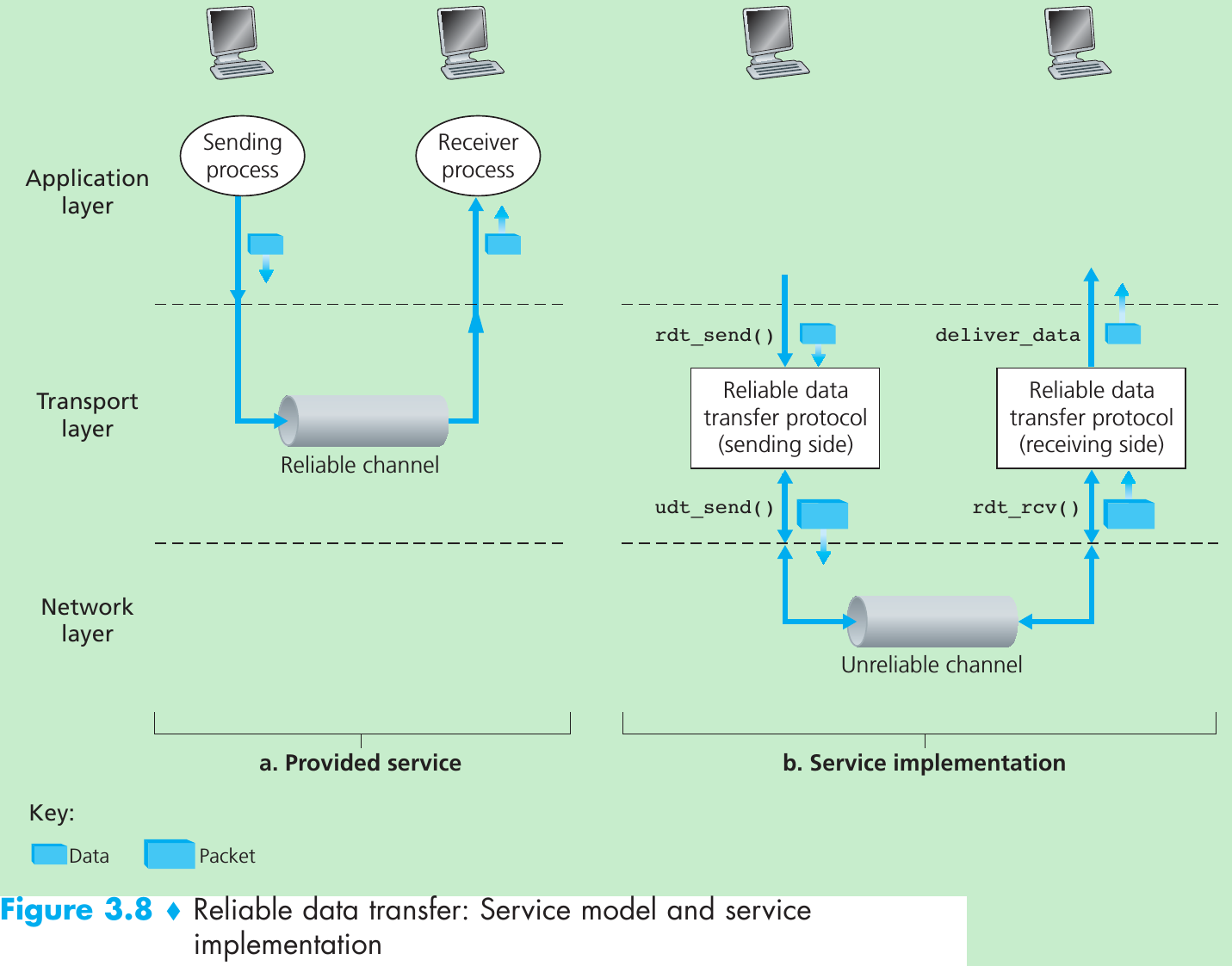
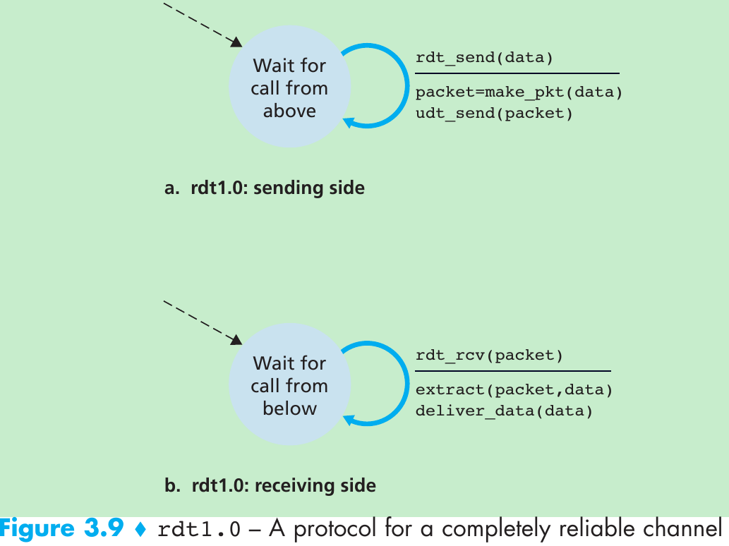
Reliable Data Transfer over a Perfectly Reliable Channel: rdt1.0
| Mechanism | Use, Comments |
|---|---|
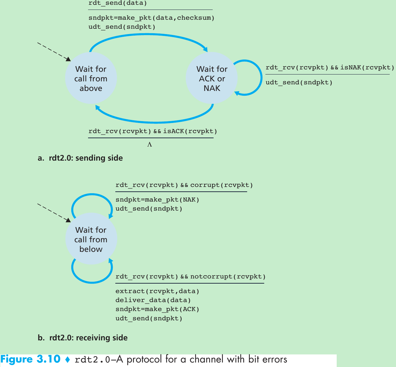
| Checksum | Used to detect bit errors in a transmitted packet. |
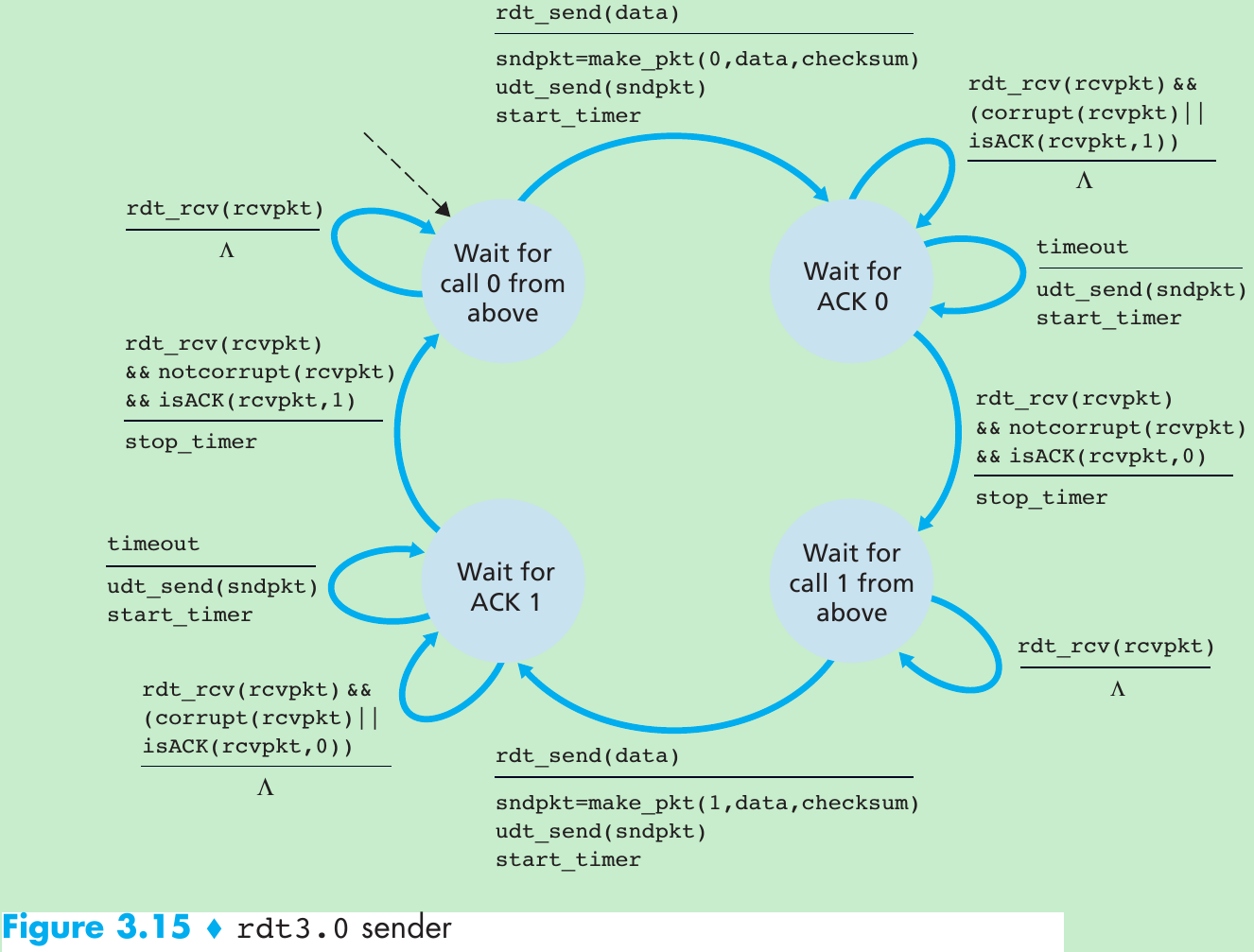
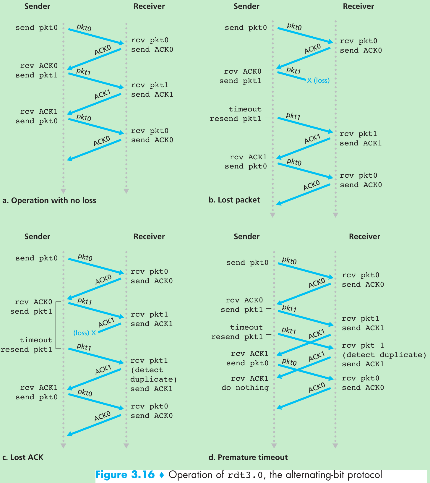
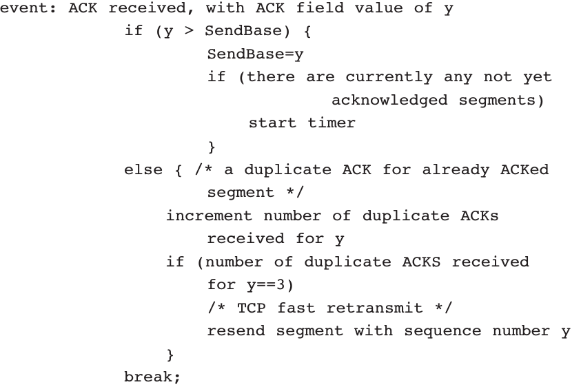
| Timer | Used to timeout/retransmit a packet, possibly because the packet (or its ACK) was lost within the channel. Because timeouts can occur when a packet is delayed but not lost (premature timeout), or when a packet has been received by the receiver but the receiver-to-sender ACK has been lost, duplicate copies of a packet may be received by a receiver. |
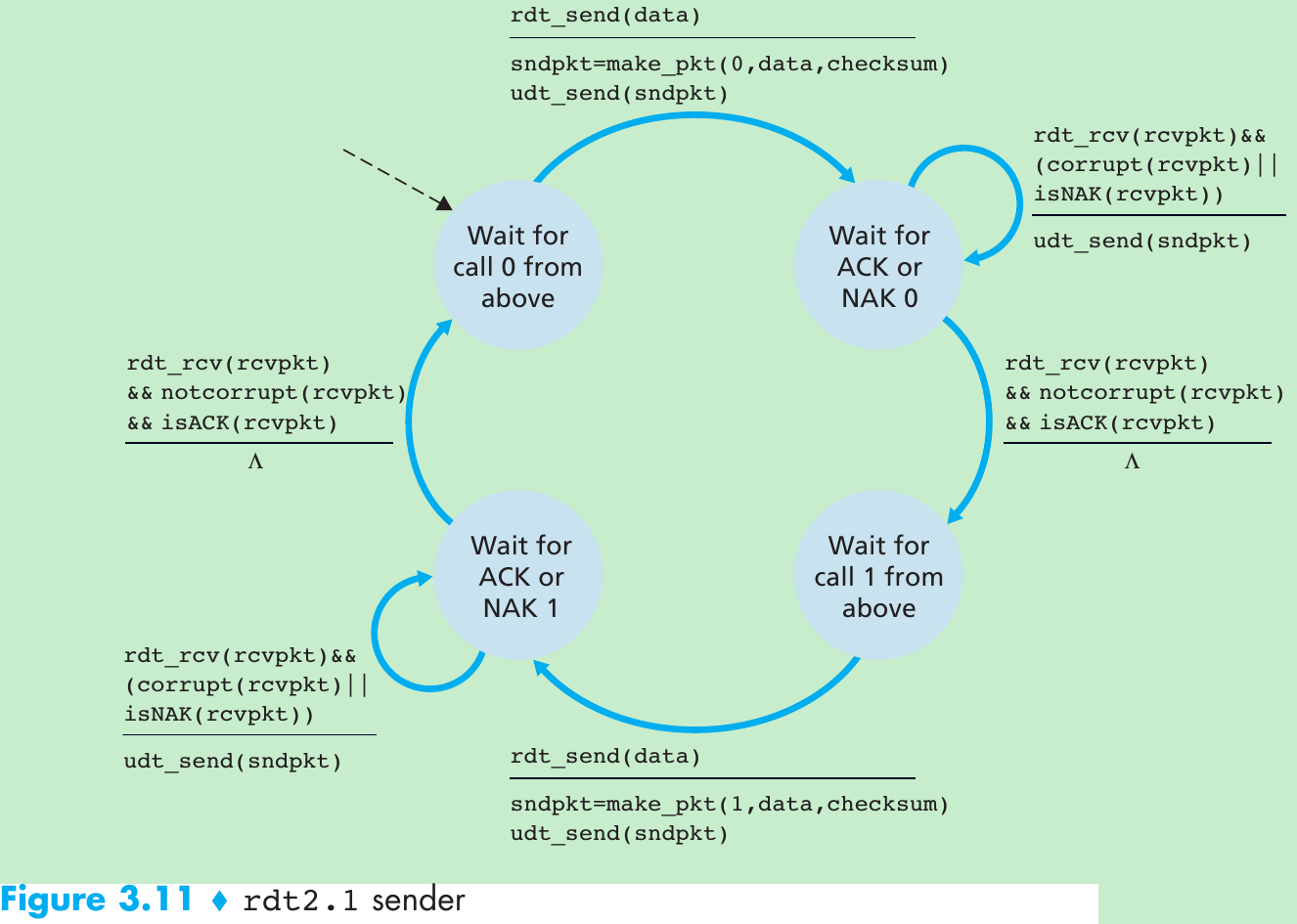
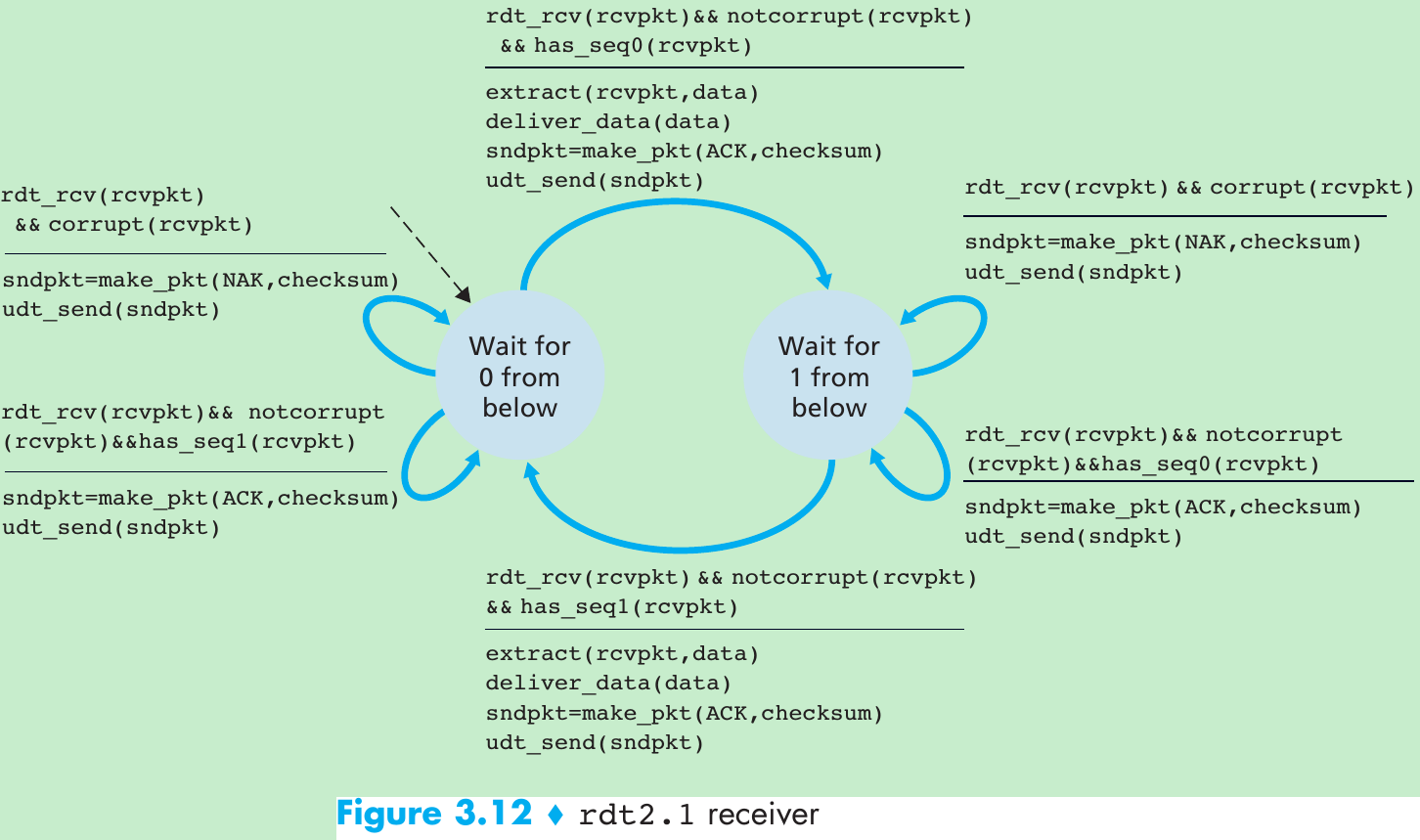
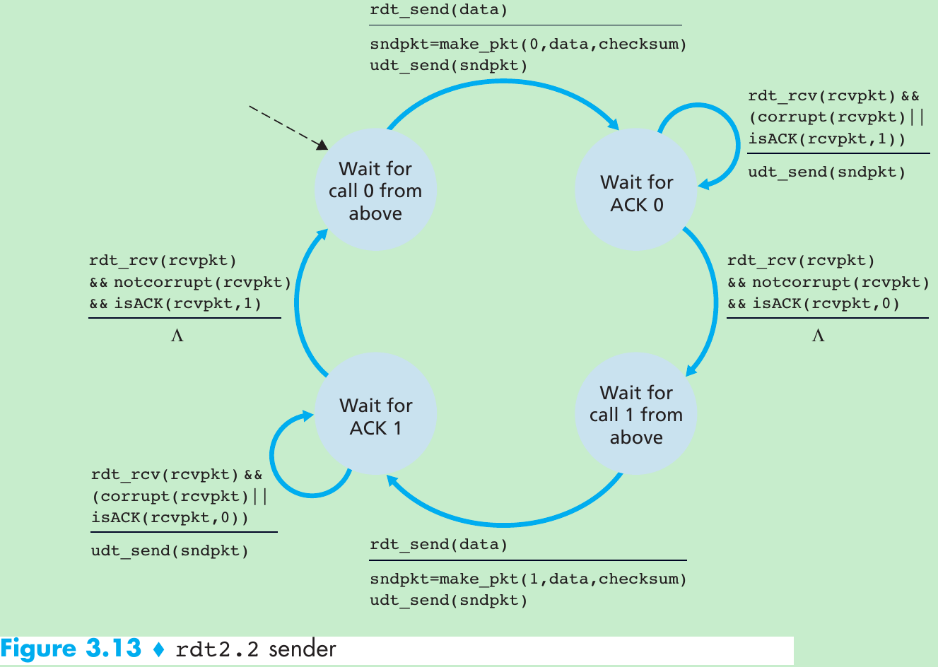
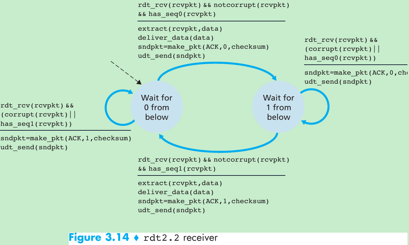
| Sequence number | Used for sequential numbering of packets of data flowing from sender to receiver. Gaps in the sequence numbers of received packets allow the receiver to detect a lost packet. Packets with duplicate sequence numbers allow the receiver to detect duplicate copies of a packet. |
| Acknowledgment | Used by the receiver to tell the sender that a packet or set of packets has been received correctly. Acknowledgments will typically carry the sequence number of the packet or packets being acknowledged. Acknowledgments may be individual or cumulative, depending on the protocol. |
| Negative acknowledgment | Used by the receiver to tell the sender that a packet has not been received correctly. Negative acknowledgments will typically carry the sequence number of the packet that was not received correctly. |
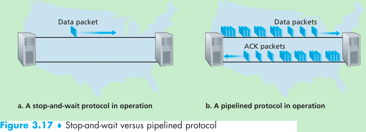
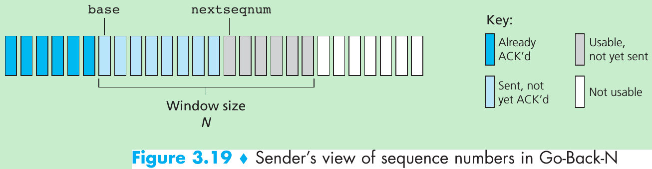
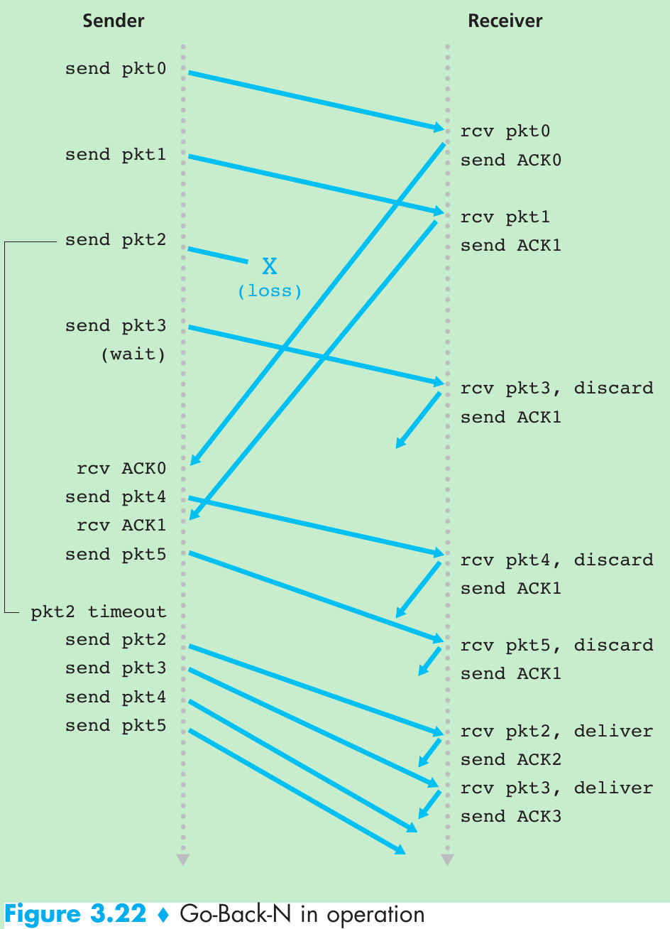
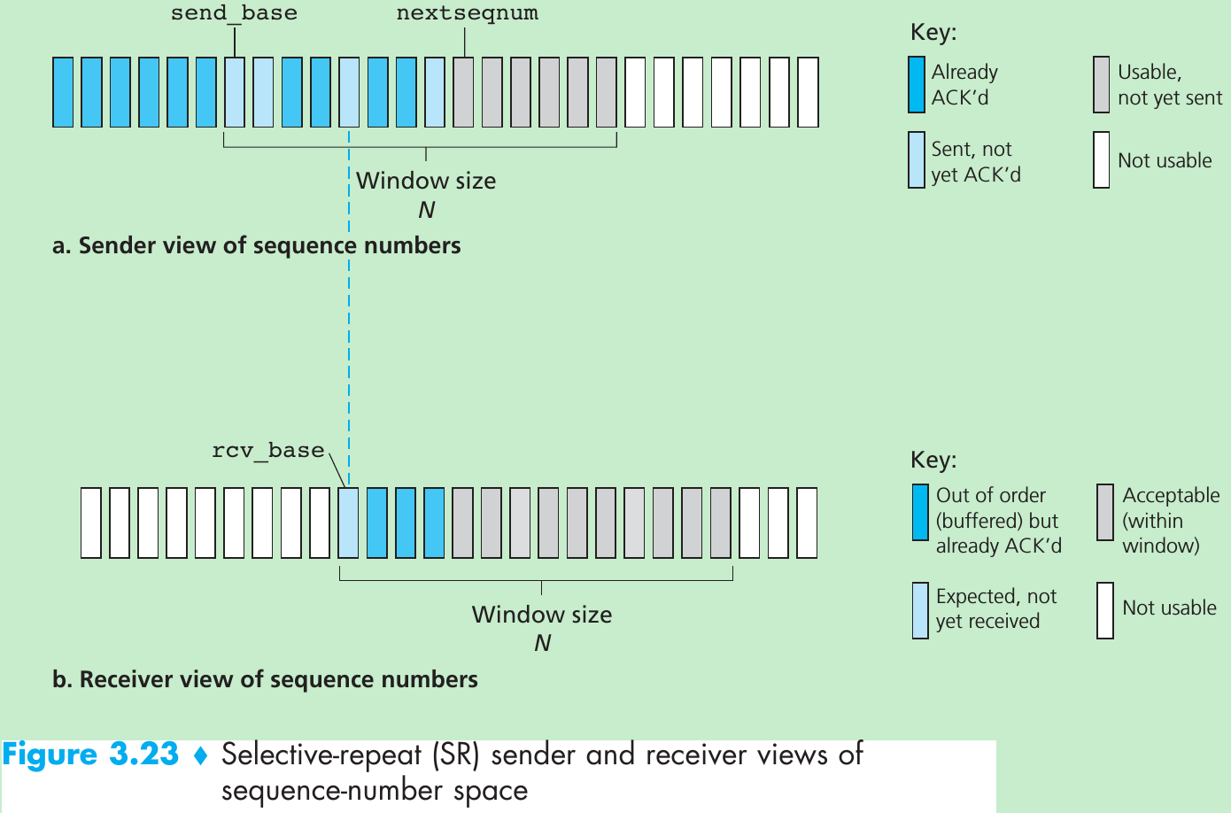
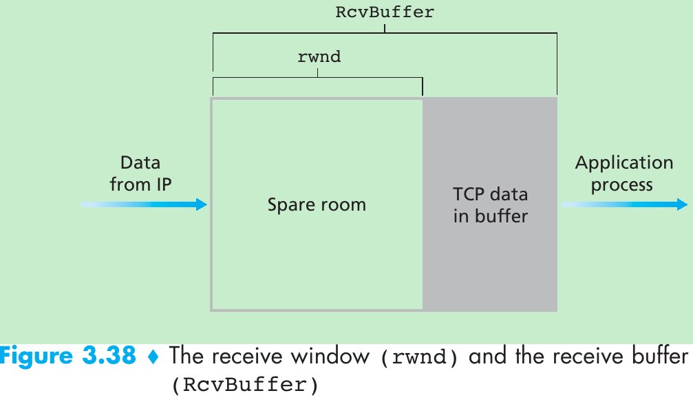
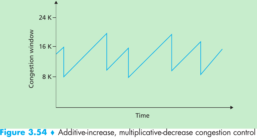
| Window, pipelining | The sender may be restricted to sending only packets with sequence numbers that fall within a given range. By allowing multiple packets to be transmitted but not yet acknowledged, sender utilization can be increased over a stop-and-wait mode of operation. We’ll see shortly that the window size may be set on the basis of the receiver’s ability to receive and buffer messages, or the level of congestion in the network, or both. |
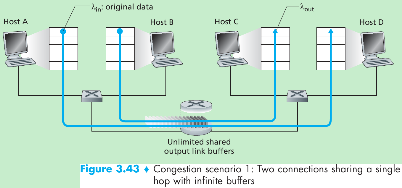
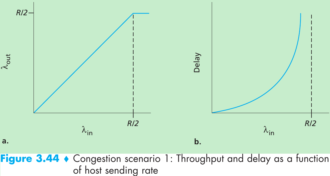
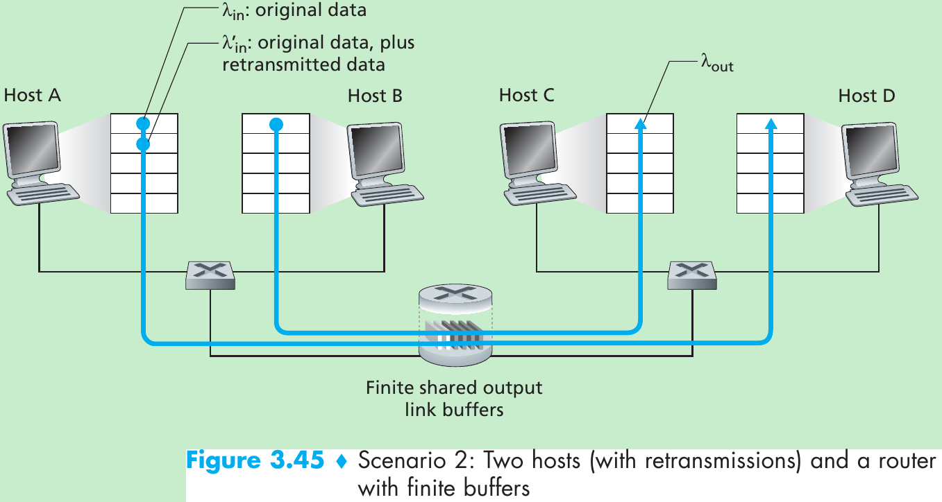
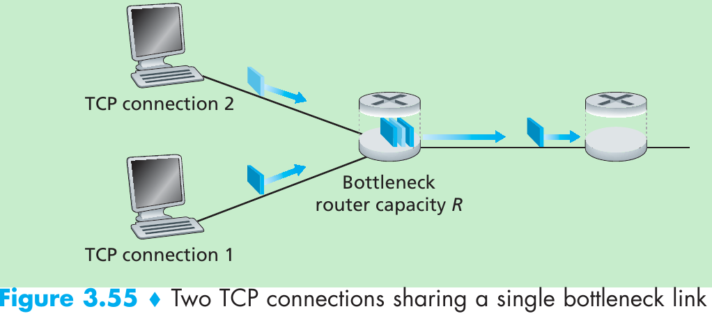
Scenario 1: Two Senders, a Router with Infinite Buffers
Please indicate the source: http://blog.csdn.net/gaoxiangnumber1
Welcome to my github: https://github.com/gaoxiangnumber1
标签:
原文地址:http://blog.csdn.net/gaoxiangnumber1/article/details/51938911