标签:
一. 介绍
存储器的最初结构为线性,它在任何时刻,地址线中都只能有一位有效。设容量为N×M的存储器有S0-Sn-1条地址线;当容量增大时,地址选择线的条数也要线性增多,利用地址译码虽然可有效地减少地址选择线的条数,但这种存储器的长宽比太大,显然,这在工业上是无法实现的。而且由于连线的延时与连线的长度成正比,这样的设计会使存储器的存取速度很慢。为了解决这个问题,现在常用的存储器都是将存储单元设计成阵列形状,使其长宽比接近1:1。这样,电路就必须增加一个列地址译码器,才能选出正确的存储单元。这样,整个存储器的地址线被分为行地址线和列地址线,行地址线要选择执行读或写操作的行,而列地址线则可从被选中的一行中再选出一个用于真正执行读或写操作的存储单元。
SDRAM的行地址线和列地址线是分时复用的,即地址线要分两次送出,先送行地址线,再送列地址线。这样可进一步减少地址线的数量、提高器件的性能,但寻址过程会由此变得复杂,新型的SDRAM的容量一般比较大,如果还采用简单的阵列结构,就会使存储器的字线和位线的长度、内部寄生电容及寄生电阻都变得很大,从而使整个存储器的存取速度严重下降,实际上,现在SDRAM一般都以Bank(存储体或存储块)为组织,来将SDRAM分为很多独立的小块,然而由Bank地址线BA控制Bank之间的选择;SDRAM的行、列地址线贯穿所有的Bank;每个Bank的数据位宽同整个存储器的相同。这样,Bank内的字线和位线的长度就可被限制合适的范围内,从而加快存储器单元的存取速度,另外,BA也可以使被选中的Bank处于正常工作模式,而使没有被选中的Bank工作在低功耗模式下,这样还可以降低SDRAM的功耗。
为了减少MOS管的数量、降低功耗、提高集成度和存储容量,SDRAM都是利用其内部电容存储信息,由于电容的放电作用,必须每隔一段时间给电容充电才能使存储在电容里的数据信息不丢失,这就是刷新过程,这种机制使SDRAM的控制过程变的更加复杂,从而给应用带来难度。
二. 信号
SDRAM的基本信号如下:
1) 控制信号:片选(SC#),同步时钟(CLK),时钟有效(CLKEN),读写选择(WE#),数据有效(DQM)等;
2) 地址选择信号:行地址选择(RAS#),列地址选择(CAS#),行/列地址线(SA0-SA12)分时复用,Bank地址线(BA0-BA1);
3) 数据信号:双向数据端口(DQ0-DQ15)。
>>地址线A10用于“预充电”(precharge)。A10低电平对某一bank预充电,A10高电平对所有bank预充电。
>>CKE高电平自动刷新,CKE低电平自刷新。
>>DQM:输入输出掩码 input/output mask, DQM is sampled HIGH and is an input mask signal for write access and an output enable signal for read access. LDQM corresponds to DQ[7:0], and UDQM corresponds to DQ[15:8]. read时,DQM高电平时,DQ输出高阻态,数据不可用;DQM低电平时,DO提供有效数据。write时,DQM高电平,相应数据忽略;DQM低电平时,相应数据写入内存。
三. 工作方式
SDRAM工作时每个bank只允许打开1行,即只允许对打开的行进行读写操作,如果要对同一bank中的其他行进行读写操作,则必须先用预充电(precharge)命令关闭已经打开的行,再用激活(active)命令打开需要进行读写操作的行。发送激活命令时要同时给出bank地址和行地址,选定需要打开的行,等待一定时间间隔(tRCD)后再给出列地址。DDR2的行列地址线是复用的,通过列地址选通信号CAS可以区分行地址与列地址。
SDRAM采用突发方式进行数据传输,即对同一行中相邻的存储单元连续进行数据传输,连续传输所涉及的存储单元(列)的数量就是突发长度(Burst Lengths)。工作时只要给出起始地址和突发长度,SDRAM就会依次自动对后面相应数量的列进行读写操作。SDRAM支持的突发长度为1、2、4、8或全页。
SDRAM采用电容存储数据信息,电容的漏电造成数据丢失,必须要定时刷新才不会丢失。为了保存内部数据,DDR2每隔一定的时间就要对每一行进行刷新。根据SDRAM的JEDEC标准,最多每隔7.8us就要刷新一次,用来保持DDR2内部数据的正确性。DDR2有两种刷新模式:自刷新(self-refresh)和自动刷新(auto-refresh)。自刷新通常工作于所有bank都处于空闲的状态,功耗低,但是进入自刷新模式和退出自刷新模式都要经过复杂的时序步骤来完成,控制复杂。自动刷新模式由定时器产生刷新命令,易于控制,因此一般选择自动刷新模式。
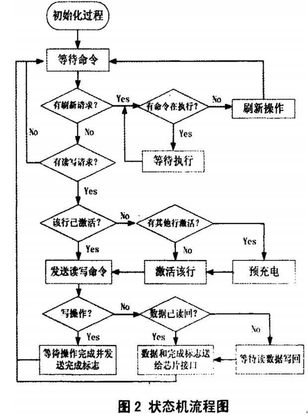
上电后控制器首先执行的是初始化过程,然后才是读写操作。在读写过程中,会遇到刷新请求,刷新的优先权要高于读写操作。如果刷新操作与读写操作冲突,则控制器会先通知用户停止发送读写命令,并等待现有的读写操作完成,然后进行刷新操作。
执行读写操作时,控制器会先根据映射的行地址来判断操作所需要的行是否已经激活,如果已经激活,则直接发送列地址;如果没激活且在不同的bank中,则先发送激活命令再发送列地址和读写命令;如果没激活且在相同的bank中,则先要发送预充电命令关闭已经打开的行,然后依次发送激活命令和读写命令。
如果执行读操作,则在读命令发出后,要等待读数据传回,根据DQM信号来接收读数据。
四. 命令
对内存的操作,就是内存控制器执行内存芯片提供的命令。一般内存芯片都有命令:模式寄存器设置、激活、预充电、读命令、写命令、突发终止、自刷新、自动刷新、空操作等。以MT48LC16M16A2为例,介绍其支持的命令。
inhibit:抑制,禁止
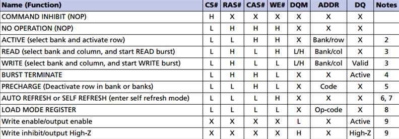
5. A10 LOW:BA0,BA1决定哪个bank预充电,A10 HIGH:所有bank预充电(BA0,BA1无关)。
6. This command is AUTO REFRESH if CKE is HIGH, SELF REFRESH if CKE is LOW.
7. Internal refresh counter controls row addressing; all inputs and I/Os are “Don’t Care” except for CKE.
8. A[11:0] define the op-code written to the mode register
初始化操作
SDRAM在上电以后必须先对其进行初始化操作,而后才能对其进行其他操作。出初始化操作具体步骤如下:
(1)SDRAM在上电以后需要等待100-200μs,在等待时间结束后还至少要执行一条空操作命令;
(2)SDRAM执行一条预充电命令后,要执行一条空操作命令,这两个操作会使所有的存储单元进行一次预充电,从而使所有阵列中的器件处于待机状态;
(3)SDRAM要执行两条自刷新命令,每一条刷新命令之后,都要执行一条空操作命令,这些操作可使SDRAM芯片内部的刷新及计数器进入正常运行状态,以便SDRAM为模式寄存器编程做好准备;
(4)执行加载模式寄存器(LOAD MODE REGISTER)命令,完成对SDRAM工作模式的设定。
完成以上步骤后,SDRAM即可进入正常工作状态,以等待外部命令对其进行读、写、预充电和刷新等操作。
ACTIVE
The ACTIVE command is used to activate a row in a particular bank for a subsequent access. The value on the BA0, BA1 inputs selects the bank, and the address provided selects the row. This row remains active for accesses until a PRECHARGE command is issued to that bank. A PRECHARGE command must be issued before opening a different row in the same bank.
READ
The READ command is used to initiate a burst read access to an active row. The values on the BA0 and BA1 inputs select the bank; the address provided selects the starting column location. The value on input A10 determines whether auto precharge is used. If auto precharge is selected, the row being accessed is precharged at the end of the READ burst; if auto precharge is not selected, the row remains open for subsequent accesses. Read data appears on the DQ subject to the logic level on the DQM inputs two clocks earlier. (提前两个时钟周期DQM已设置好,read时内存芯片负责DQM输出) If a given DQM signal was registered HIGH, the corresponding DQ will be HighZ two clocks later; if the DQM signal was registered LOW, the DQ will provide valid data.
WRITE
The WRITE command is used to initiate a burst write access to an active row. The values on the BA0 and BA1 inputs select the bank; the address provided selects the starting column location. The value on input A10 determines whether auto precharge is used. If auto precharge is selected, the row being accessed is precharged at the end of the write burst; if auto precharge is not selected, the row remains open for subsequent accesses. Input data appearing on the DQ is written to the memory array, subject to(受制于) the DQM input logic level appearing coincident with the data. If a given DQM signal is registered LOW, the corresponding data is written to memory; if the DQM signal is registered HIGH, the corresponding data inputs are ignored and a WRITE is not executed to that byte/column location.
PRECHARGE
The PRECHARGE command is used to deactivate the open row in a particular bank or the open row in all banks. The bank(s) will be available for a subsequent row access a specified time (tRP) after the PRECHARGE command is issued. Input A10 determines whether one or all banks are to be precharged, and in the case where only one bank is precharged, inputs BA0 and BA1 select the bank. Otherwise BA0 and BA1 are treated as “Don’t Care.” After a bank has been precharged, it is in the idle state and must be activated prior to any READ or WRITE commands are issued to that bank.
BURST TERMINTE
The BURST TERMINATE command is used to truncate either fixed-length or continuous page bursts. The most recently registered READ or WRITE command prior to the BURST TERMINATE command is truncated.
刷新
刷新有两种方式,自动刷新(AUTO REFRESH)和自刷新(SELF REFRESH)。
Mode Register
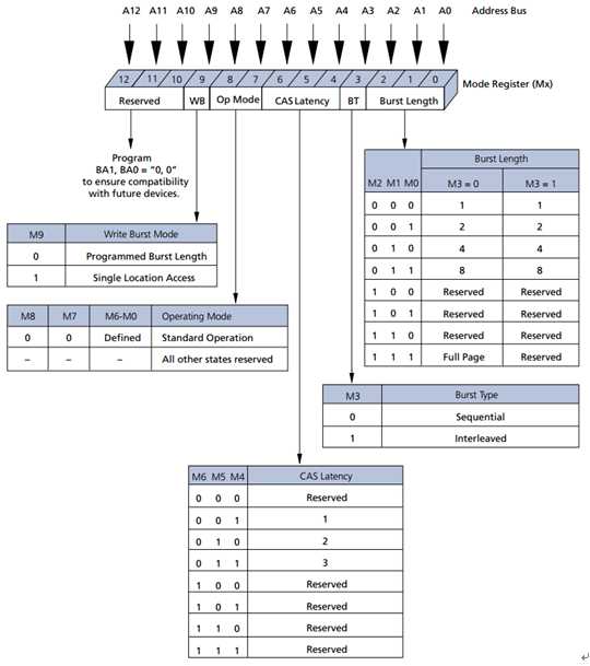
The mode register defines the specific mode of operation, including burst length (BL), burst type, CAS latency (CL), operating mode, and write burst mode. The mode register is programmed via the LOAD MODE REGISTER command and retains the stored information until it is programmed again or the device loses power.
Mode register bits M[2:0] specify the BL; M3 specifies the type of burst; M[6:4] specify the CL; M7 and M8 specify the operating mode; M9 specifies the write burst mode; and M10–Mn should be set to zero to ensure compatibility with future revisions. Mn+ 1 and Mn+ 2 should be set to zero to select the mode register.
The mode registers must be loaded when all banks are idle, and the controller must wait tMRD before initiating the subsequent operation. Violating either of these requirements will result in unspecified operation.
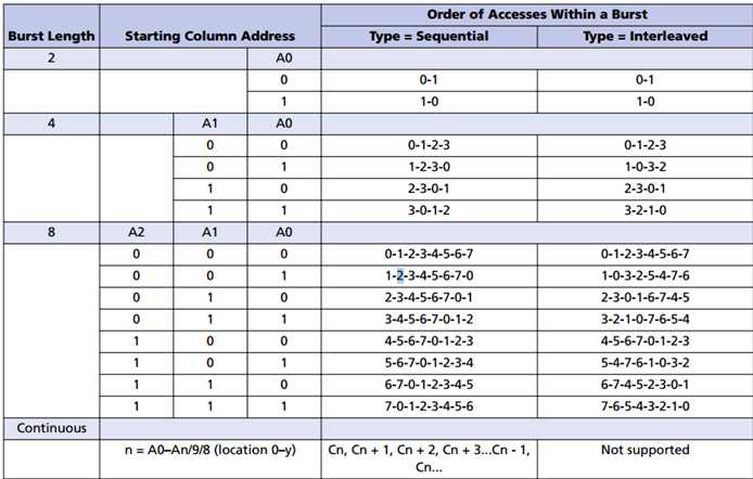
When a READ or WRITE command is issued, a block of columns equal to the burst length is effectively selected. All accesses for that burst take place within this block, meaning that the burst wraps within the block when a boundary is reached. The block is uniquely selected by A[8:1] when BL = 2, A[8:2] when BL = 4, and A[8:3] when BL = 8. The remaining (least significant) address bit(s) is (are) used to select the starting location within the block. Continuous page bursts wrap within the page when the boundary is reached.
The ordering of accesses within a burst is determined by the burst length, the burst type, and the starting column address.
CAS Latency
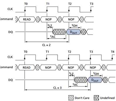
The CAS latency (CL) is the delay, in clock cycles, between the registration of a READ command and the availability of the output data. The latency can be set to two or three clocks.
If a READ command is registered at clock edge n, and the latency is mclocks, the data will be available by clock edge n + m. The DQ start driving as a result of the clock edge one cycle earlier (n + m- 1), and provided that the relevant access times are met, the data is valid by clock edge n + m. For example, assuming that the clock cycle time is such that all relevant access times are met, if a READ command is registered at T0 and the latency is programmed to two clocks, the DQ start driving after T1 and the data is valid by T2.
Write Burst Mode
When M9 = 0, the burst length programmed via M[2:0] applies to both READ and WRITE bursts; when M9 = 1, the programmed burst length applies to READ bursts, but write accesses are single-location (nonburst) accesses.
Bank/Row Activation
After a row is opened with the ACTIVE command, a READ or WRITE command can be issued to that row, subject to the tRCD specification. tRCD (MIN) should be divided by the clock period and rounded up to the next whole number to determine the earliest clock edge after the ACTIVE command on which a READ or WRITE command can be entered. tRCD 由时钟周期决定,并且要延迟到最小时钟周期。For example, a tRCD specification of 20ns with a 125 MHz clock (8ns period) results in 2.5 clocks, rounded to 3. This is reflected in Figure 21 (page 49), which covers any case where 2 < tRCD (MIN)/tCK ≤3. (The same procedure is used to convert other specification limits from time units to clock cycles.)
五.timing
CL :CAS(READ) latency,列选择到数据输出的时间。
tRAS:ACTIVE-to-PRECHARGE command
tRC:ACTIVE-to-ACTIVE command period
tRCD:ACTIVE-to-READ or WRITE delay,行选择(RAS)到列选择(CAS)延迟。
tRP:PRECHARGE command period
tRRD:ACTIVE bank a to ACTIVE bank b command
2-2-2组合的含义是:CAS延迟,RAS到CAS的延迟和RAS预充电时间。第一个数字是取得列地址的延迟时间,第二个数字是行和列地址之间的延 迟,第三个数字是存储单元充电时间,预充电实际上是对行数据进行读操作。
六.more
参考:
标签:
原文地址:http://www.cnblogs.com/embedded-linux/p/5731490.html