标签:
There are commonly three types of memories in a PIC Microcontroller, Flash Program Memory, Data Memory (RAM) and EEPROM Data Memory. We write Programs in the Flash Program Memory of a microcontroller. Flash memory makes it possible to program a microcontroller many times before installing to device and even after the installation we can change the program. RAM Data Memory is used for storing data temporarily during program execution and it is volatile. That is, this memory is cleared when the power is gone or after CPU reset. RAM Data Memory locations are also called General Purpose Registers (GPR). These two memories have faster response time. The third memory is EEPROM memory which is an abbreviation for Electrically Erasable Programmable Read Only Memory. EEPROM memory can be read and write electrically, can be accessed through program. It is a non volatile memory but has slower response time. EEPROM memory can be used to store data such as sensor logs, device parameters which should not be loss during power loss or CPU reset. Here I using PIC 16F877A for explanation.
The data in the EEPROM and Flash Program Memory can be read/write during normal operations (over full VDD range). These memories are not mapped in the register file space, instead of it can be accessed through the following six Special Function Registers (SFR) for read and write operations.
EEDATA register hold 8-bit data for read/write and EEADR holds the address of EEPROM memory location to be accessed. PIC Microcontrollers usually have 128/256 bytes of data EEPROM memory with address ranging from 00h to FFh. On devices having 128 bytes, memory locations from 80h to FFh are unimplemented and will be wraparound to beginning of the data EEPROM memory. On-Chip charge pump (used while writing data to EEPROM) is turned off when writing these unimplemented locations. EEDATH and EEADRH registers are used when interfacing program memory block with Program Flash Memory. Here we deals only with EEPROM data memory.
EEPROM data memory allows only single byte read and write. When a data byte is written in to EEPROM, automatically erases the particular location first and then writes the new data (erase before write). The write time is controlled by and on-chip timer and write/erase voltages are generated automatically by an on-chip charge pump. When the device is code protected, program or data memory will not be accessible to programmer but CPU may read or write data EEPROM memory.
EECON1 is the control register used for memory access.
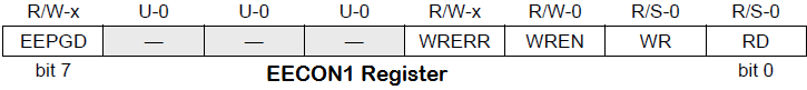
EEPGD control bit is used to select Program Memory or Data Memory access. If it is set Program Memory is selected and vice versa. Control bits RD, WR are used to initiate read, write, erase operations. These bit cannot be cleared in program, only able to set. These bits are cleared in hardware on the completion of read or write operations.
The WREN control bit is the Write Enable bit, when set it enables write or erase operation. On power-up, the WREN bit will be automatically cleared. The WRERR bit is the Write Error Flag bit, it sets when a write (or erase) operation is interrupted by a MCLR or a WDT Time-out Reset during normal operation. In these situations, we can check the WRERR bit and rewrite the location as the data and address will be unchanged in the EEDATA and EEADR registers.
On the completion of write operation Interrupt flag bit, EEIF in the PIR2 register is set. It must be cleared in program.
EECON2 register is not a physical register and it is used exclusively in the EEPROM write sequence. Reading EECON2 will read all zeros.
unsigned char readEEPROM(unsigned char address)
{
  EEADR = address; //Address to be read
  EECON1.EEPGD = 0;//Selecting EEPROM Data Memory
  EECON1.RD = 1; //Initialise read cycle
  return EEDATA; //Returning data
}
void writeEEPROM(unsigned char address, unsigned char datas)
{
  unsigned char INTCON_SAVE;//To save INTCON register value
  EEADR = address; //Address to write
  EEDATA = datas; //Data to write
  EECON1.EEPGD = 0; //Selecting EEPROM Data Memory
  EECON1.WREN = 1; //Enable writing of EEPROM
  INTCON_SAVE=INTCON;//Backup INCON interupt register
  INTCON=0; //Diables the interrupt
  EECON2=0x55; //Required sequence for write to internal EEPROM
  EECON2=0xAA; //Required sequence for write to internal EEPROM
  EECON1.WR = 1; //Initialise write cycle
  INTCON = INTCON_SAVE;//Enables Interrupt
  EECON1.WREN = 0; //To disable write
  while(PIR2.EEIF == 0)//Checking for complition of write operation
  {
    asm nop; //do nothing
  }
  PIR2.EEIF = 0; //Clearing EEIF bit
}
To read or write data to EEPROM, you may use built-in MikroC Libraries or user defined functions as following.
MikroC PRO for PIC Microcontrollers provides library to work with Internal EEPROM. We can easily read/write form EEPROM using the following library functions.
Prototype: unsigned short EEPROM_Read(unsigned int address);
Eeprom_Read function reads data from a specified address. Note that parameter address is of integer type, which implies that this functions supports microcontrollers with more than 256 bytes of EEPROM. There must me atleast 20ms delay between successive using of these routines.
Prototype: void EEPROM_Write(unsigned int address, unsigned short data);
EEPROM_Write function write data to the specified address. As I said above, since the address parameter is of integer type, it supports microcontrollers with more than 256 bytes of EEPROM. There must me atleast 20ms delay between successive using of these routines. Beware that all Interrupts will be disabled during the execution of this function.
Note: Address ranges from 00h to FFh for devices having 256 bytes while for 128 bytes devices it is 00h to 7Fh.
void main()
{
  unsigned int a, i;
  TRISC = 0;
  do
  {
    for(i=0,a=1;i<8;i++)
    {
      EEPROM_Write(i, a);
      a = a<<1;
    }

    for(i=0;i<8;i++)
    {
      PORTC = EEPROM_Read(i);
      Delay_ms(1000);
    }
  }while(1);
}

Note: VDD and VSS of the pic microcontroller is not shown in the circuit diagram. VDD should be connected to +5V and VSS to GND.
In this example we writes 00000001 to the first memory location, 00000010 to second, 000000100 to third etc sequentially up to 10000000. Then it is read sequentially and output through PORTC.
You can download the hex file, MikroC source code, Proteus files etc here.
文章来源: https://electrosome.com/internal-eeprom-pic-microcontroller/
Using Internal EEPROM of PIC Microcontroller
标签:
原文地址:http://www.cnblogs.com/harleygwak1206/p/5821557.html