标签:put esc image 读取 复位 addition 对齐 dev lock
---恢复内容开始---
针对xilinx FIFO IP核进行简单的学习,整个流程参考http://www.eefocus.com/guoke1993102/blog/15-06/313183_36284.html,仿真工具使用modelsim.
FIFO ip核设置参照链接设置,本文不再贴图,其中部分设置更改如下:
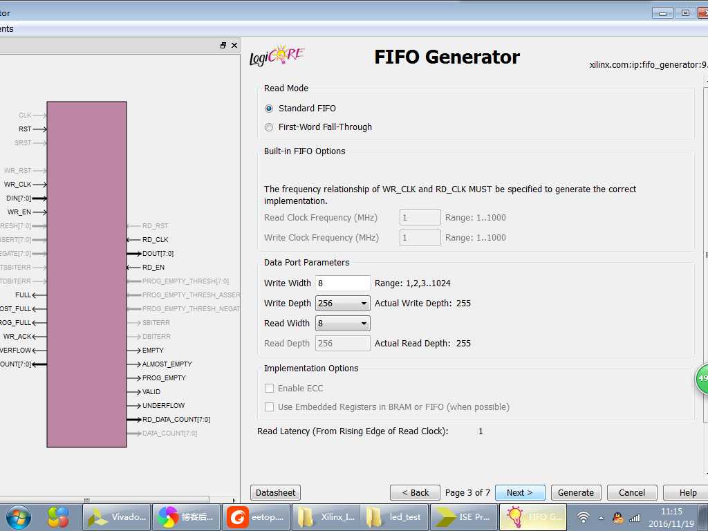
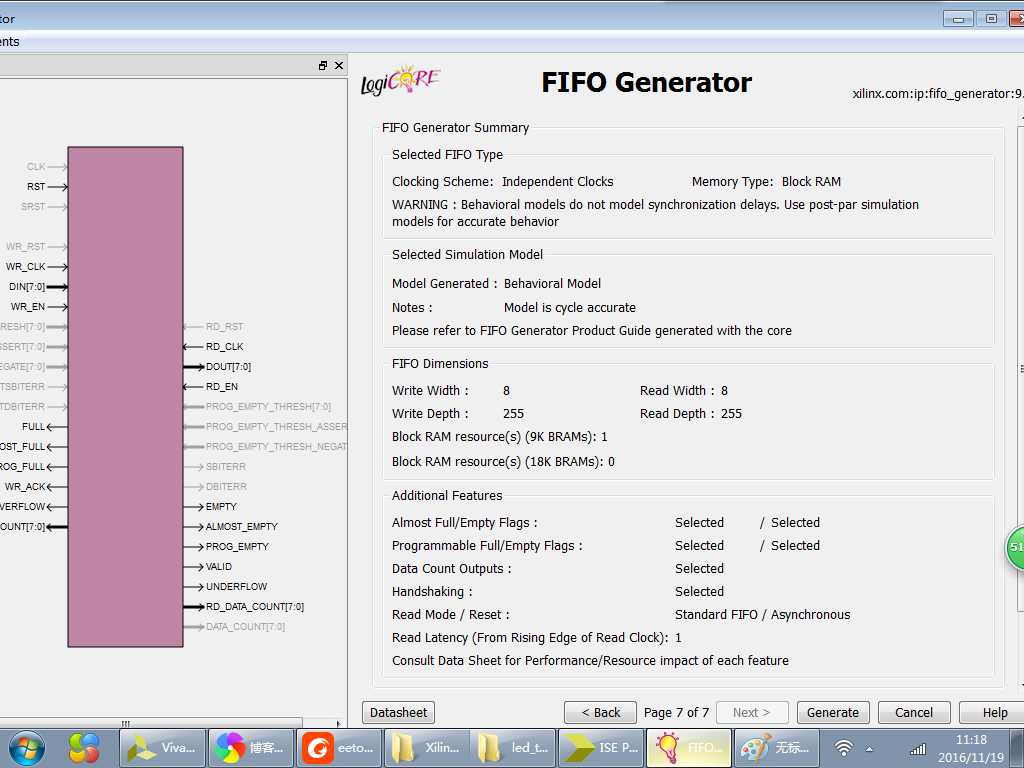
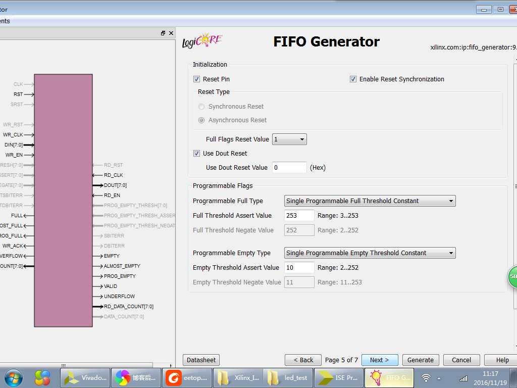
之后开始编写程序,程序代码如下:
  1 `timescale 1ns / 1ps
  2 //////////////////////////////////////////////////////////////////////////////////
  3 // Company:
  4 // Engineer:
  5 //
  6 // Create Date:    19:34:55 11/14/2016
  7 // Design Name:
  8 // Module Name:    FIFO_test
  9 // Project Name:
 10 // Target Devices:
 11 // Tool versions:
 12 // Description:
 13 //
 14 // Dependencies:
 15 //
 16 // Revision:
 17 // Revision 0.01 - File Created
 18 // Additional Comments:
 19 //
 20 //////////////////////////////////////////////////////////////////////////////////
 21 module FIFO_test(
 22                         input clk,
 23                         input rstin_n,
 24
 25                         output wire [7:0] dout
 26
 27     );
 28 wire clk_50M;
 29 wire clk_100M;
 30
 31 wire             rst_n;
 32
 33 reg [7:0]     din;//写入FIFO中数据
 34 wire             wr_en;
 35 reg [2:0]     cnt;
 36
 37 wire             full;//FIFO满
 38 wire            empty;
 39
 40 wire             rd_en;
 41
 42 wire             valid;
 43 wire            wr_ack;
 44
 45 wire             overflow;
 46 wire            underflow;
 47
 48 wire             almost_empty;
 49 wire             almost_full;
 50
 51 wire [7:0]     rd_data_count;
 52 wire [7:0]     wr_data_count;
 53
 54 wire            prog_full;
 55 wire            prog_empty;
 56
 57
 58 assign wr_en = (!full && !rd_en && (cnt == 3‘d5)) ?  1‘b1 : 1‘b0;//非满时写,且满后就不再写了,即便之后数据被读取导致非满
 59 assign rd_en = (empty == 1‘b0 && wr_en == 1‘b0) ? 1‘b1 : 1‘b0;//写时不读取,写完再读取
 60
 61 //----------写FIF数据---------------------------
 62 always @(posedge clk_50M or negedge rst_n)
 63      if(!rst_n)
 64         begin
 65             din <= 8‘d0;
 66             cnt <= 3‘d0;
 67         end
 68     else
 69         begin
 70             if(full)
 71                 begin
 72                     din <= 8‘d0;
 73                 end
 74             else if(wr_en)
 75                 begin
 76                     din <= din + 8‘d1;
 77                 end
 78             else
 79                 begin
 80                     din <= din;
 81                 end
 82
 83             if(cnt == 3‘d5)
 84                 begin
 85                     cnt <= cnt;
 86                 end
 87             else
 88                 begin
 89                     cnt <= cnt + 3‘d1;
 90                 end
 91         end
 92
 93 fifo_ip FIFO_ip (
 94                       .rst(!rst_n), // input rst
 95                       .wr_clk(clk_50M), // input wr_clk
 96                       .rd_clk(clk_100M), // input rd_clk
 97                       .din(din), // input [7 : 0] din
 98                       .wr_en(wr_en), // input wr_en
 99                       .rd_en(rd_en), // input rd_en
100                       .dout(dout), // output [3 : 0] dout
101                       .full(full), // output full
102                       .almost_full(almost_full), // output almost_full
103                       .wr_ack(wr_ack), // output wr_ack
104                       .overflow(overflow), // output overflow
105                       .empty(empty), // output empty
106                       .almost_empty(almost_empty), // output almost_empty
107                       .valid(valid), // output valid
108                       .underflow(underflow), // output underflow
109                       .rd_data_count(rd_data_count), // output [7 : 0] rd_data_count
110                       .wr_data_count(wr_data_count), // output [7 : 0] wr_data_count
111                       .prog_full(prog_full), // output prog_full
112                       .prog_empty(prog_empty) // output prog_empty
113                     );
114
115   pll_ip PLL_ip(                                // Clock in ports
116                          .CLK_IN1(clk),      // IN
117                             // Clock out ports
118                          .CLK_OUT1(clk_50M),     // OUT
119                          .CLK_OUT2(clk_100M),     // OUT
120                          // Status and control signals
121                          .RESET(!rstin_n),// IN
122                          .LOCKED(rst_n) // OUT
123                          );
124
125 //ILA和ICON定义
126 //ILA和ICON定义
127 wire [35:0] CONTROL0;
128 wire [127:0] TRIG0;
129
130
131 ICON ICON (
132                  .CONTROL0(CONTROL0) // INOUT BUS [35:0]
133               );
134
135 ILA ILA (
136             .CONTROL(CONTROL0), // INOUT BUS [35:0]
137             .CLK(clk_100M), // IN
138             .TRIG0(TRIG0) // IN BUS [15:0]
139         );
140
141 assign TRIG0[7:0]  = din;
142 assign TRIG0[8]     = wr_en;
143 assign TRIG0[9]     = wr_ack;
144 assign TRIG0[10]     = full;
145 assign TRIG0[11]     = almost_full;
146 assign TRIG0[12]     = overflow;
147 assign TRIG0[13]     = empty;
148 assign TRIG0[14]     = prog_full;
149 assign TRIG0[15]     = prog_empty;
150
151
152 assign TRIG0[23:16] = dout;
153 assign TRIG0[24]      = rd_en;
154 assign TRIG0[25]      = valid;
155 assign TRIG0[26]      = underflow;
156
157
158 endmodule
仿真代码如下:
`timescale 1ns / 1ps

////////////////////////////////////////////////////////////////////////////////
// Company:
// Engineer:
//
// Create Date:   20:19:58 11/14/2016
// Design Name:   FIFO_test
// Module Name:   D:/Xilinx_Project/FIFO_test/vtf_FIFO_test.v
// Project Name:  FIFO_test
// Target Device:
// Tool versions:
// Description:
//
// Verilog Test Fixture created by ISE for module: FIFO_test
//
// Dependencies:
//
// Revision:
// Revision 0.01 - File Created
// Additional Comments:
//
////////////////////////////////////////////////////////////////////////////////

module vtf_FIFO_test;

    // Inputs
    reg clk;
    reg rstin_n;

    // Outputs
    wire [3:0] dout;

    // Instantiate the Unit Under Test (UUT)
    FIFO_test uut (
        .clk(clk),
        .rstin_n(rstin_n),
        .dout(dout)
    );

    initial begin
        // Initialize Inputs
        clk = 0;
        rstin_n = 0;

        // Wait 100 ns for global reset to finish
        #1000;
        rstin_n = 1;
        // Add stimulus here
    end

always #10 clk = ~clk;


endmodule
查看仿真波形:
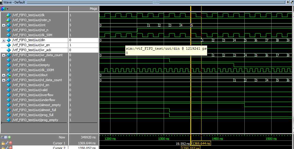
从上图可以看出wr_en型号对应数据从0开始写入,而对应wr_ack延时一个时钟,表示数据写入成功,wr_data_count延时wr_ack一个时钟表示写入到FIFO中的数据个数,由于rd_data_count对应于读FIFO时钟域,对应也可能会延时写多个时钟才出现,在此不做考虑。
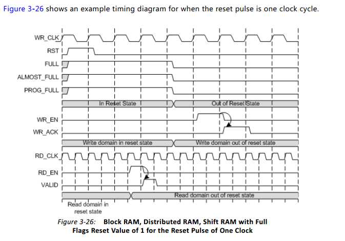
注意:对应FIFO手册上说明:复位完成后需要延时3个时钟才能进行FIFO读写操作,则从仿真波形上也可以看出full信号在复位完成3个时钟之后才拉低,所以这点需要注意一下。
In this configuration, the FIFO requires a minimum asynchronous reset pulse of 1 write clock
period (WR_CLK/CLK). After reset is detected on the rising clock edge of write clock, 3 write
clock periods are required to complete proper reset synchronization. During this time, the
FULL, ALMOST_FULL, and PROG_FULL flags are asserted. After reset is deasserted, these
flags deassert after three clock periods (WR_CLK/CLK) and the FIFO can then accept write
operations.
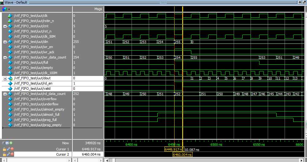
上图读操作:由于采用的是常规读操作模式,则置高rd_en一个时钟之后读数据才输出,对应valid有效信号延时rd_en一个时钟,valid正好对齐dout。
注意full ,almost_full等信号的变化,almost_full延时一个时钟之后full信号才置高,都是跟随写时钟变化的。full信号跟随写时钟,empty信号跟随读时钟。
pro_full时跟随写时钟变化的,当wr_data_count满足设置的wr_data_count >=253时pro_full就会置高。
pro_empty跟随读时钟变化,当rd_data_count满足设置的rd_data_count <= 2时peo_empty就会置高。
标签:put esc image 读取 复位 addition 对齐 dev lock
原文地址:http://www.cnblogs.com/estop-jfw/p/6080411.html