标签:des style blog http color os io ar strong
Techniques for configuring a?hypervisor?scheduler?to make use of cache topology of processors and physical memory distances between NUMA nodes when making scheduling decisions. In the same or other embodiments the?hypervisor scheduler?can be configured to optimize the scheduling of latency sensitive workloads. In the same or other embodiments a?hypervisor?can be configured to expose a virtual cache topology to a guest operating system running in a virtual machine.
A virtual machine may have one or more virtual processors that are exposed to a guest operating system as single core processors. When a guest operating system runs a workload, it schedules a thread on a virtual processor. A hypervisor?runs and schedules a thread that represents the virtual processor on a logical processor of a physical machine that hosts the VM (virtual machine). The workload in the thread runs and some, hopefully useful, work is performed. The?hypervisor?then runs another thread on the same, or a different logical processor. The?hypervisor?scheduler?thus must determine both when and where to schedule a particular virtual processor. Proper placement of the virtual processors is a key to maintaining high levels of performance.
Currently, hypervisors treat the logical processors the same. For example, a hypervisor?may schedule a virtual processor to run in a first NUMA node (Non-Uniform Memory Architecture node) and then move it to another NUMA node. This technique ensures that workloads are run as fast as possible and any overhead due to cache misses is tolerated.
The decision to expose virtual processors as single core processors was made to make virtualization of the physical architecture of the host machine easier. For example, guest operating systems are written so that the topology is checked on boot. If the guest was moved to another host with a different topology it may operate inefficiently because the resources it expects are no longer present.
As systems that include logical processors that share various different caches become more common, it would be beneficial to configure a?hypervisor?to leverage them. Moreover, it would be beneficial to expose some sort of cache topology to a guest operating system so that the?scheduler?in the guest operating system can also make intelligent scheduling decisions.
Techniques are disclosed for configuring a?hypervisor?to leverage the physical cache topology of a host computer system. In an exemplary embodiment, the hypervisor?is configured to make use of processor topology, cache hierarchies, and the distance between memories. For example, in an exemplary embodiment, a method includes an operation for causing a list of idle logical processors to be generated in response to receiving a request to schedule a thread indicative of a virtual processor of a virtual machine; and an operation for causing the thread indicative of the virtual processor to be scheduled on a logical processor from the list that shares a level of cache with a seed logical processor.
In another exemplary embodiment, a method includes an operation for exposing a plurality of single core virtual processors to a virtual machine; an operation for generating a list of idle logical processors in response to receiving a request to execute a thread indicative of a single core virtual processor; an operation for identifying logical processors currently executing threads indicative of single core virtual processors of the virtual machine; and an operation for scheduling the thread indicative of the virtual processor on a logical processor from the list that shares a cache with a maximum number of logical processors currently executing the threads indicative of the single core virtual processors of the virtual machine.
An yet another exemplary embodiment, a method includes an operation for causing a thread indicative of a virtual processor of a virtual machine to be assigned a distinct logical processor to execute thereon; an operation for causing a list of idle logical processors to be generated in response to receiving a request to execute the thread indicative of a virtual processor; and an operation for causing the thread indicative of the virtual processor to be scheduled on a logical processor that shares a level of cache with the distinct logical processor assigned to execute the thread indicative of the virtual processor. In addition to the foregoing, other aspects are described in the claims, drawings, and text forming a part of the disclosed subject matter.
It can be appreciated by one of skill in the art that one or more various aspects described herein may include but are not limited to circuitry and/or programming for effecting the herein-referenced aspects described herein; the circuitry and/or programming can be virtually any combination of hardware, software, and/or firmware configured to effect the herein-referenced aspects depending upon the design choices of the system designer.
The foregoing is a summary and thus contains, by necessity, simplifications, generalizations and omissions of detail. Those skilled in the art will appreciate that the summary is illustrative only and is not intended to be in any way limiting.
FIG. 1?depicts an example computer system wherein the subject matter described herein can be implemented.
FIG. 2?depicts an operational environment wherein the subject matter described herein can be implemented.
FIG. 3?depicts an operational environment wherein the subject matter described herein can be implemented.
FIG. 4?illustrates a datacenter wherein the subject matter described herein can be implemented.
FIG. 5?depicts an operational environment wherein the subject matter described herein can be implemented.
FIG. 6?depicts operational procedure.
FIG. 7?depicts an alternative embodiment of the operational procedure of?FIG. 6.
FIG. 8?depicts operational procedure.
FIG. 9?depicts an alternative embodiment of the operational procedure of?FIG. 8.
FIG. 10?depicts operational procedure.
FIG. 11?depicts an alternative embodiment of the operational procedure of?FIG. 10.
FIG. 12?depicts an operational procedure.
FIG. 13?depicts an alternative embodiment of the operational procedure of?FIG. 12.
Embodiments may execute on one or more computer systems.?FIG. 1?and the following discussion are intended to provide a brief general description of a suitable computing environment in which the disclosed subject matter may be implemented.
Referring now to?FIG. 1, an exemplary computing system?100?is depicted. Computer system?100?can include logical processor?102, e.g., an execution core. While one logical processor?102?is illustrated, in other embodiments computer system?100?may have multiple logical processors, e.g., multiple execution cores per processor substrate and/or multiple processor substrates that could each have multiple execution cores. As shown by the figure, various computer readable storage media?110?can be interconnected by one or more system busses that couple various system components to the logical processor?102. The system buses may be any of several types of bus structures including a memory bus or memory controller, a peripheral bus, and a local bus using any of a variety of bus architectures. In example embodiments, the computer readable storage media?110?can include for example, random access memory (RAM)?104, storage device?106, e.g., electromechanical hard drive, solid state hard drive, etc., firmware?108, e.g., FLASH RAM or ROM, and removable storage devices?118?such as, for example, CD-ROMs, floppy disks, DVDs, FLASH drives, external storage devices, etc. It should be appreciated by those skilled in the art that other types of computer readable storage media can be used such as magnetic cassettes, flash memory cards, and/or digital video disks.
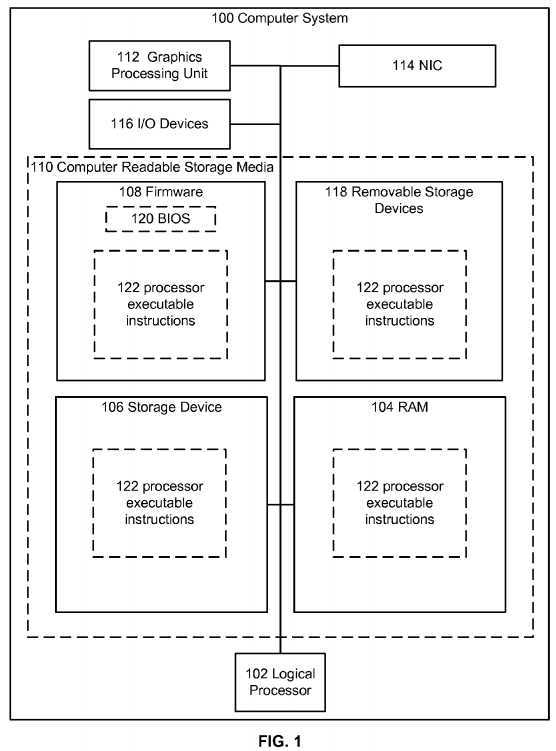
The computer readable storage media?110?can provide nonvolatile and volatile storage of executable instructions?122, data structures, program modules and other data for the computer?100?such executable instructions that effectuate manager?250described in the following figures. A basic input/output system (BIOS)?120, containing the basic routines that help to transfer information between elements within the computer system?100, such as during start up, can be stored in firmware?108. A number of programs may be stored on firmware?108, storage device?106, RAM?104, and/or removable storage devices118, and executed by logical processor?102?including an operating system and/or application programs.
Commands and information may be received by computer?100?through input devices?116?which can include, but are not limited to, a keyboard and pointing device. Other input devices may include a microphone, joystick, game pad, scanner or the like. These and other input devices are often connected to logical processor?102?through a serial port interface that is coupled to the system bus, but may be connected by other interfaces, such as a parallel port, game port or universal serial bus (USB). A display or other type of display device can also be connected to the system bus via an interface, such as a video adapter which can be part of, or connected to, a graphics processor unit?112. In addition to the display, computers typically include other peripheral output devices (not shown), such as speakers and printers. The exemplary system of?FIG. 1?can also include a host adapter, Small Computer System Interface (SCSI) bus, and an external storage device connected to the SCSI bus.
Computer system?100?may operate in a networked environment using logical connections to one or more remote computers, such as a remote computer. The remote computer may be another computer, a server, a router, a network PC, a peer device or other common network node, and typically can include many or all of the elements described above relative to computer system?100.
When used in a LAN or WAN networking environment, computer system?100?can be connected to the LAN or WAN through network interface card?114. The NIC?114, which may be internal or external, can be connected to the system bus. In a networked environment, program modules depicted relative to the computer system?100, or portions thereof, may be stored in the remote memory storage device. It will be appreciated that the network connections described here are exemplary and other means of establishing a communications link between the computers may be used. Moreover, while it is envisioned that numerous embodiments of the disclosed subject matter are particularly well-suited for computerized systems, nothing in this document is intended to limit the disclosed subject matter to such embodiments.
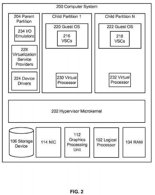
Turning to?FIG. 2,?hypervisor?microkernel?202?can be configured to control and arbitrate access to the hardware of computer system?200. Broadly,?hypervisor?microkernel?202?can generate execution environments called partitions such as child partition?1?through child partition N (where N is an integer greater than 1). In embodiments a child partition is the basic unit of isolation supported by?hypervisor?microkernel?202. That is, each child partition can be mapped to a set of hardware resources, e.g., memory, devices, logical processor cycles, etc., that is under control of the?hypervisor?microkernel?202?and hypervisor?microkernel?202?can isolate processes in one partition from accessing another partition‘s resources, e.g., a guest operating system in one partition may be isolated from the memory of another partition and thus may not be able to detect memory addresses outside of its partition. In embodiments,?hypervisor?microkernel?202?can be a stand-alone software product, a part of an operating system, embedded within firmware of the motherboard, one or more specialized integrated circuits, or a combination thereof.
Hypervisor?microkernel?202?can enforce partitioning by restricting a guest operating system‘s view of system memory. Guest memory is a partition‘s view of memory that is controlled by a?hypervisor. The guest physical address can be backed by system physical address (SPA), i.e., the memory of the physical computer system, managed by?hypervisor. In an embodiment, the GPAs and SPAs can be arranged into memory blocks, i.e., one or more pages of memory. When a guest writes to a block using its page table, the data is actually stored in a block with a different system address according to the system wide page table used by?hypervisor.
In the depicted example, parent partition component?204, which can also be also thought of as similar to domain 0 of Xen‘s open source?hypervisor, can interact with?hypervisor?microkernel?202?to provide a virtualization layer. Parent partition?204?in this operational environment can be configured to provide resources to guest operating systems executing in the child partitions 1-N by using virtualization service providers?228?(VSPs) that are typically referred to as back-end drivers in the open source community. Broadly, VSPs?228?can be used to multiplex the interfaces to the hardware resources by way of virtualization service clients (VSCs) (typically referred to as front-end drivers in the open source community) and communicate with the virtualization service clients via communication protocols. As shown by the figures, virtualization service clients can execute within the context of guest operating systems. These drivers are different than the rest of the drivers in the guest in that they may be supplied with a?hypervisor, not with a guest.
As shown by the figure emulators?234, e.g., virtualized integrated drive electronics device (IDE devices), virtualized video adaptors, virtualized NICs, etc., can be configured to run within the parent partition?204?and are attached to resources available to guest operating systems?220?and?222. For example, when a guest OS touches a register of a virtual device or memory mapped to the virtual device?202, microkernel?hypervisor?can intercept the request and pass the values the guest attempted to write to an associated emulator.
Each child partition can include one or more virtual processors (230?and?232) that guest operating systems (220?and?222) can manage and schedule threads to execute thereon. Generally, the virtual processors are executable instructions and associated state information that provide a representation of a physical processor with a specific architecture. For example, one virtual machine may have a virtual processor having characteristics of an Intel x86 processor, whereas another virtual processor may have the characteristics of a PowerPC processor. The virtual processors in this example can be mapped to logical processors of the computer system such that the instructions that effectuate the virtual processors will be backed by logical processors. Thus, in an embodiment including multiple logical processors, virtual processors can be simultaneously executed by logical processors while, for example, other logical processors execute?hypervisor?instructions. The combination of virtual processors and memory in a partition can be considered a virtual machine.
Guest operating systems can include any operating system such as, for example, operating systems from Microsoft?, Apple?, the open source community, etc. The guest operating systems can include user/kernel modes of operation and can have kernels that can include schedulers, memory managers, etc. Generally speaking, kernel mode can include an execution mode in a logical processor that grants access to at least privileged processor instructions. Each guest operating system can have associated file systems that can have applications stored thereon such as terminal servers, e-commerce servers, email servers, etc., and the guest operating systems themselves. The guest operating systems can schedule threads to execute on the virtual processors and instances of such applications can be effectuated.
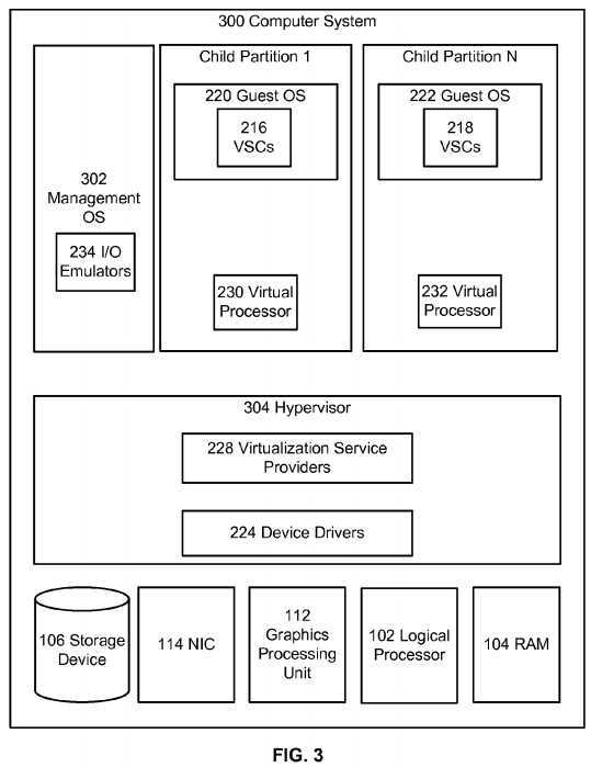
Referring now to?FIG. 3, it illustrates an alternative architecture to that described above in?FIG. 2.?FIG. 3?depicts similar components to those of?FIG. 2; however in this example embodiment the?hypervisor?304?can include the microkernel component and components from the parent partition?204?of?FIG. 2?such as the virtualization service providers?228?and device drivers?224?while management operating system?302?may contain, for example, configuration utilities used to configure?hypervisor?304. In this architecture?hypervisor?304?can perform the same or similar functions as?hypervisor microkernel?202?of?FIG. 2; however, in this architecture?hypervisor?304?can be configured to provide resources to guest operating systems executing in the child partitions.?Hypervisor?304?of?FIG. 3?can be a standalone software product, a part of an operating system, embedded within firmware of the motherboard or a portion of?hypervisor?304?can be effectuated by specialized integrated circuits.
Briefly,?FIG. 4?depicts an operational environment for implementing the disclosed subject matter. For example, a number of computer systems?404-410?can be coupled together in a datacenter?400?(While four computer systems are depicted, one of skill in the art can appreciate that datacenter?400?can include more or fewer computer systems). The depicted computer systems can have different topologies and, moreover, they can have different characteristics, e.g., different amounts of RAM, different RAM speeds, different amount of logical processors, and/or logical processors with different speeds or instruction sets.
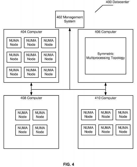
As shown by the figure, computer system?406?has a symmetric multiprocessing topology (SMP) or a ‘flat‘ topology. Generally, SMP is a computer architecture that includes a plurality of processors that are connected to a single shared memory. In this arraignment, a memory controller can manage the flow of data to and from memory. Memory access may be uniform with respect to each logical processor and each logical processor can access the entire range of memory, i.e., system physical addresses. This topology works well for computer systems with a relatively small number of processors, but when the computer system includes many processors, all competing for access to the shared memory bus, performance of the system can decrease. Moreover, the complexity of the computer system significantly increases which in turn drives the price per processor up.
Computer systems?404,?408, and?410?have NUMA nodes. NUMA based computer systems are can be generally thought of as computers that are made up of smaller computer systems. In this example, each NUMA node can include one or more logical processors and local memory. The memory inside of a NUMA node is considered local memory and memory in other NUMA nodes is considered remote memory because the only the processors inside of the node are connected to the same memory bus. The NUMA nodes are interconnected by cache coherency domain interconnects which allow processors in one NUMA node to access memory in other NUMA nodes in a coherent way. Thus, system physical addresses are uniform with respect to each processor. Or put another way, system physical address 20,000 is the same for every processor in the computer system. The difference is that for some processors memory address 20,000 is a local memory address, e.g., inside their NUMA node, and for other processors memory address 20,000 is remote, e.g., outside their NUMA node. Generally, local memory can be accessed faster than remote memory and the relationship between local v. remote access time is called a NUMA ratio. A NUMA ratio of 1 to 2 means that it costs twice as many processor cycles to access a particular remote system physical address than a local system physical address. NUMA alleviates bottlenecks caused by SMP systems by limiting the number of processors on any one memory bus and is generally less expensive than a SMP computer system with the same amount of logical processors.
Turning to?FIG. 5, it illustrates an operational environment wherein the disclosed subject matter can be implemented. As one skilled in the art can appreciate, the disclosed subject matter does not have to be implemented in a computer system having the illustrated architecture. Instead, the illustrated architecture is merely an exemplar used to explain concepts. Accordingly, the disclosed subject matter can be incorporated into different environments including different amounts of NUMA nodes, virtual machines, cache topologies, logical processors, etc.
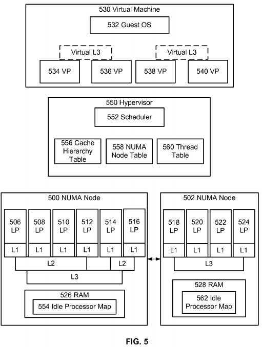
FIG. 5?shows two example NUMA nodes (500?and?502) connected by a cache coherency domain interconnect. The illustrated NUMA nodes have different cache topologies. For example, each processor in NUMA node?500?shares level 3 ("L3") cache and two groups of processors share a level 2 ("L2") cache. Each processor (506-516) is shown with its own level 1 ("L1") cache. Logical processors (518-524) in NUMA node?502?share a level 3 cache and have their own level 1 cache. Those of skill in the art can appreciate that the illustrated cache topologies are for illustration purposes only and the disclosed subject matter is not limited to being implemented in a system with any particular cache topology. Each NUMA node (500?and?502) is also shown as including its own random access memory (526?and?528).
Processor cache is typically used for temporary storage of instructions and data herein referred to as information. When a request is made, a logical processor requires instructions for executing that request and data to execute the instruction with. Since the logical processor operates at speeds greater than RAM, high speed caches have been added to processors and algorithms have been devised to anticipate what information a logical processor will need and attempt to store it in caches. Typically, level 1 cache is very small, which allows it to be very fast having latency times of, for example, two cycles, i.e., the number of processor cycles needed to access the memory and retrieve the information. If the information is not present in L1 cache, a cache miss occurs and the logical processor checks its L2 cache, which is a slightly larger pool of memory with a little longer latency of around, for example, nine cycles. If the data is not in L2 or L1, the logical processor checks its L3 cache. L3 cache is far larger than L1 and L2 and its latency is, for example, twenty three cycles. With each cache miss logical processor looks to its next level of cache until it has to fetch the information from RAM or mass storage.
Hypervisor?550, i.e., microkernel?hypervisor?202?of?FIG. 2?or?hypervisor?304?of?FIG. 3, can include?scheduler?552?which can be configured to schedule threads indicative of virtual processors to run on one of the logical processors (506-516?or?518-524). In order to determine how to schedule an incoming thread,?hypervisor?scheduler?552?can access various information (554-562) described in more detail below.
Thread table?560, which could be a data structure stored in memory, can store information about the different virtual processor threads. When a request to run a virtual processor is received,?scheduler?552?can access thread table?560?and retrieve information about the virtual processor in order to determine where and how to schedule it. For each virtual processor, thread table?560?may store, for example, a timestamp identifying when the thread last ran, whether the thread has been identified to be a latency sensitive thread, the logical processor the thread last ran on, the identity of an ideal processor for the thread, the NUMA node the thread last ran in, information that describes the identity of related virtual processor threads, etc.
In an exemplary embodiment, thread table?560?can be used by?scheduler?552?to schedule virtual processor threads. For example,?scheduler?552?can be configured to select an idle processor to run an incoming thread that is located within a seed NUMA node, e.g., an ideal NUMA node, or the node that last ran the thread. In this example embodiment,?scheduler552?can check thread table?560?to determine the seed NUMA node for an incoming thread request and schedule the thread on the seed NUMA node.
In a specific example, each NUMA node can maintain a per-NUMA node idle processor map (554?and?562). For example, an idle processor map can be a bitmap where each bit represents a logical processor. When a logical processor runs a thread, it can set the bit and when it finishes running the thread, it can reset the bit. The idle processor map can be used byscheduler?552?to determine which logical processors are idle. In an exemplary embodiment, the bitmap can be broken into multiple maps: one for each NUMA node in the computer system stored in the NUMA node. This embodiment reduces the collisions on the map because it reduces the number of processors attempting to access the same memory to set and reset bits.
Moreover, by maintaining a map for each NUMA node,?scheduler?552?can quickly remove logical processors from a list of candidates by checking the idle processor map associated with a specific NUMA node. For example, an incoming thread may have its seed NUMA node set as NUMA node?500?in thread table?560, i.e., the thread may have last ran on that node or a processor in the node is set as an ideal processor.?Scheduler?552?can receive this information and search idle processor map?554?for an idle processor. In this example?scheduler?552?eliminated logical processors?518-524?from a list of candidates without having to access idle processor map?562?or process any information in it.
In the event that the seed NUMA node does not have an idle processor,?scheduler?552?can be configured to search for an idle processor from the next closest NUMA node by accessing information in NUMA node table?558, which can be a data structure stored in memory. For example, NUMA node table?558?can include a node distance graph for each NUMA node in the computer system.?Hypervisor?550?can generate an array that ranks the NUMA nodes according to memory distance. For example, the graph for NUMA node?500?would show that NUMA node?502?is close.?Hypervisor?550?can generate the graph for each node when the host system boots. For example,?hypervisor?550?can direct each logical processor in a NUMA node to access RAM from all the other nodes in the host; record the round trip times and rank the times from best to worst; the best time indicating the closest node and the worst time indicating the farthest node.
Once a NUMA node is selected by?scheduler?552, various algorithms can be used to select a specific logical processor. In a simple example, one where the virtual machine has one virtual processor,?scheduler?552?can determine the seed logical processor for a thread and if that thread is unavailable,?scheduler?552?can access a cache hierarchy table?556?to determine where to schedule the thread. Cache hierarchy table?556?can include an array of bitmaps for each logical processor that describes how it shares caches with other logical processors in its NUMA node. For example, logical processor?506?may have 3 arrays (one for L1, L2, and L3 caches) an L1 array that has a bit set for logical processor?506?and nulls for 508-516, an array for L2 that has a bit set for LP?506-510, and an array for L3 that shows bits set for LPs?506-516. In an example,?scheduler?552?can be configured to select an idle logical processor that shares a highest level of cache with the seed. For example, if the seed is LP?506?scheduler?552?could select LP?508, LP?510, or LP?512?if any is idle since L2 is the highest cache these processors share.
In an exemplary embodiment, the seed logical processor can be set to the last processor that ran the thread. For example, if a virtual machine includes one logical processor it most efficiently runs on the logical processor that last ran it because this logical processor has the highest chance of having information the virtual processor needs in its cache. In this example embodiment as the virtual processor is moved the seed can be changed to the logical processor that last ran it.
The complexity of the scheduling algorithm can increase as the number of virtual processors assigned to a virtual machine increases. For example, when a virtual machine includes multiple virtual processors it has been noticed by the inventors that they tend to use the same information. Thus, if the virtual processors are scheduled on logical processors that share caches the number of cache hits increases which causes the guest to run more efficiently. In this example,?scheduler?552?can select logical processors to run virtual processors of a virtual machine in such a way that the virtual processors share physical caches. This technique reduces the chance that cache misses occur and in the event that one does occur, the information fetched for one virtual processor can be used by the other virtual processors. This technique additionally reduces coherence miss costs. For example, if a virtual processor needs exclusive access to the cache line, the cost of transferring the cache line from the logical processor running the virtual processor to another logical processor is reduced since the information can be moved through their shared cache rather than having to be written all the way back to memory or sent through an inter-socket bus.
In an exemplary embodiment, one where multiple virtual processors are executing within a virtual machine, each virtual processor can be assigned a seed logical processor set by an administrator or automatically by a configuration program. For example, virtual processor?534?could have LP?506?set as its ideal and virtual processor?536?could have its ideal LP set to be LP?508. When?scheduler?552?attempts to schedule virtual processor?534,?scheduler?552?will determine that it‘s ideal is LP?506?and attempt to schedule it on LP?506. Since?scheduler?552?is attempting to keep threads on their ideal logical processors the number of cache hits will be increased.
In another example embodiment?scheduler?552?may not use a seed. Instead,?hypervisor?scheduler?552?can select an idle logical processor based on the location of threads of other virtual processors in a virtual machine such as virtual machine530. In this example,?scheduler?552?can be configured to select a logical processor that it estimates will have the smallest estimated miss cost. A cache miss occurs when a logical processor attempts to access information from a cache and the information is not in cache. The miss cost is the amount of cycles that would be wasted if information is not in cache. In this example embodiment?scheduler?552?can select the logical processor that has the lowest estimated miss cost.
For example,?scheduler?552?can be configured to select an idle processor that shares cache with a maximum number of logical processors currently running virtual processors of a virtual machine. In the same, or another example,?scheduler?552can be configured to select an idle processor that shares a maximum number of caches with a maximum number of logical processors currently running virtual processors of a virtual machine. In yet another exemplarily embodiment,?scheduler?552can be configured to select the logical processor that shares the highest level of cache with the most logical processors currently running virtual processors of a virtual machine. For example, and referring to?FIG. 5, in an embodiment virtual processor?534?may be running on logical processor?506, virtual processor?536?may be running on logical processor?508?and virtual processor?538?may be running on logical processor?514. In this example?scheduler?552?may receive a request to run virtual processor?540.?Scheduler?552?can check idle processor map?554?and determine that logical processors?510?and?516are free. In this example?scheduler?552?can access cache hierarchy table?556?and obtain the arrays for logical processors510?and?516.?Scheduler?552?can determine, based on information in the arrays, that logical processor?510?shares L3 cache with LP?506, LP?508, and LP?514?and logical processor?516?share L3 cache with the same LPs. In the first example above, scheduler?552?may select either LP?510?or?514. In the alternative embodiment described above,?scheduler?552?can select LP?510?since it shares L2 cache with LP?506?and?508?as well as L3 cache with LP?506, LP?508, and LP?514. In this example LP?510?shares 5 caches with LP?510?whereas LP?514?shares 3. In the third example,?scheduler?552?can select LP510?since it shares L2 cache with LP?506?and?508.
In another example embodiment?scheduler?552?can be configured to handle latency sensitive workloads differently than regular workloads when scheduling. Typically virtual processors belonging to latency sensitive guests are scheduled as soon as possible. However in this case if the last logical processor a virtual processor ran on is unavailable, the virtual processor would be migrated elsewhere and the positive effects of having cache hits would be lost. In an example embodiment scheduler?552?can be configured to maximize locality while simultaneously limited latency without affecting non-latency sensitive workloads.
For example, when?hypervisor?550?receives a request to schedule a latency sensitive thread,?scheduler?552?can determine if there are any logical processors that share cache with the last logical processor that ran the thread and select one. For example, the selected logical processor could be the logical processor that shares the highest level of cache with the processor that last ran the thread. If, no logical processors that share cache are available,?scheduler?552?can determine the amount of time since the virtual processor last ran and compare it to a predetermined threshold. If the amount of time since it is last ran is greater than the threshold the virtual processor can be migrated, otherwise it can be queued to run on the logical processor that last ran the thread. If the amount of time since the virtual processor last ran is greater than the threshold, it is assumed that useful information is not in cache. If the amount of time since it last ran is less than the threshold, the assumption is that cache still contains useful information. One skilled in the art can appreciate that the predetermined threshold can be set by a policy or an administrator and is dependent on the physical hardware and workload characteristics of the virtual machine. Over time an administrator or policy can adjust the predetermined threshold and monitor how efficiency increases or decreases until an optimum value is found for a particular host running a particular workload.
Continuing with the description of?FIG. 5, in an embodiment, a virtual cache topology can be exposed to virtual machines. In this example embodiment?hypervisor?550?can generate a virtualized topology that can be exposed to the guest.?Hypervisor550?can construct a topology that can be reasonably honored by the host computer system and, for example, any other computer system in a datacenter. This allows for a?scheduler?in the guest operating system to make intelligent scheduling decisions while maintaining the abstraction between hardware and virtual hardware.
For example, in an embodiment where virtualized topology is exposed to guest operating system?532,?hypervisor?550?can detect the cache topology of the host computer system during boot. In an example embodiment, one where the host is by itself,?hypervisor?550?can be configured to compute a virtual cache topology that can be honored by at least most of the logical processors in the computer system. In a datacenter, the host computer can send cache topology to management system?402?along with all the other computers in the datacenter. Management system?402?can then calculate a virtual topology that can be honored by at least most of the computer systems. The topology can be received by?hypervisor?550which can effectuate a virtual machine having the topology.
In a specific example,?hypervisor?550?or management system?402?can calculate a virtual topology. For example,?hypervisor550?or management system?402?can calculate a virtual topology by determining an amount of logical processors shared by a cache; expose the determined number to guest operating system; and expose a cache interconnecting the determined number that is the lowest type of cache that can be honored.
In an exemplary embodiment, and turning to?FIG. 5,?hypervisor?550?or management system?402?can calculate a virtual cache topology by determining an amount of logical processors shared by a cache (sharing cardinality); expose the sharing cardinality to a guest operating system; and expose a cache interconnecting the determined number that is the highest level of cache that can be honored (sharing level) to a guest operating system.
In one method of calculating sharing cardinality, the sharing cardinality is set as the minimum number of LPs sharing the lowest level of cache in a NUMA node. For example, and referring to?FIG. 5, in the illustrated embodiment,?hypervisor?550could detect that six LPs in NUMA node?500?and four LPs in NUMA node?502?share the lowest level cache (L3).?Hypervisor550?(or in a datacenter example, the management system?402) can then determine that the minimum amount of logical processors that share the lowest level of cache in the cluster is four, e.g., LPs?518-524?share L3. In this example, hypervisor?550?can select L3 as the type of cache to expose because?hypervisor?550?(or management system?402) determines the sharing level as the highest level of cache at which there are at least sharing cardinality number of cache sharing LPs. Thus, as illustrated by?FIG. 5, in this example,?hypervisor?550?can expose groups of four virtual processors that share a virtual L3 cache.?Hypervisor?550?can then store the information in cache hierarchy table?556.
In another method of calculating sharing cardinality, the sharing cardinality is the greatest common divisor of each NUMA node‘s number of LPs sharing the lowest level of cache in each cluster. For example, and referring to?FIG. 5, in the illustrated embodiment,?hypervisor?550?could detect the numbers of logical processors that as a group share the lowest level of cache in the cluster. In this example, NUMA node?500?includes six LPs (LPs?506-516) that share the lowest level cache, L3, and in NUMA node?502, four LPs (LPs?518-524) share the lowest level cache, L3.?Hypervisor?550?(or in a datacenter example, the management system?402) then determines that the greatest common divisor of the two groups, six processors and four processors, is two processors.?Hypervisor?550?(or management system?402) then determines that the highest level of cache in each NUMA node at which there are at least the determined number of processors (two in this example) is L3. In this example,?hypervisor?550?can select L3 as the type of cache to expose. Thus, as illustrated by?FIG. 5, in this example,?hypervisor?550?can expose groups of two virtual processors that share a virtual L3 cache.?Hypervisor550?can then store the information in cache hierarchy table?556.
After the virtual cache topology is determined (and passed by management system?402?to?hypervisor?550, in the case of a datacenter), it can be used by?scheduler?552?when scheduling threads. In one embodiment,?hypervisor?550?can set ideal logical processors for virtual processors in a way that honors the virtual cache topology. For example, and continuing the specific example from above,?hypervisor?550?can set LP?506?as the ideal processor for VP?534?and LP?508?as the ideal processor for VP?536.?Hypervisor?550?can then expose L2 cache between LP?506?and?508?as a virtual L3 cache. In this example embodiment as long as?scheduler?552?can schedule VP?534?or VP?536?on any combination of logical processors in NUMA node?500?or NUMA node?502?the virtualized topology is honored. Moreover, if the physical cache being virtualized is an L2, guest operating system?532?may observe a performance increase.
In another example,?hypervisor?550?can keep track of where virtual processors are executing and select a logical processor based on the exposed virtual topology and estimated cache miss cost associated with the available logical processors. Scheduler?552?can then determine the identities of the logical processors running other threads of virtual machine?530?and use this information to select a logical processor that honors the virtual cache topology and has the lowest estimated miss cost.
The following are a series of flowcharts depicting operational procedures. For ease of understanding, the flowcharts are organized such that the initial flowcharts present implementations via an overall "big picture" viewpoint and subsequent flowcharts provide further additions and/or details. Furthermore, one of skill in the art can appreciate that the operational procedure depicted by dashed lines are considered optional.
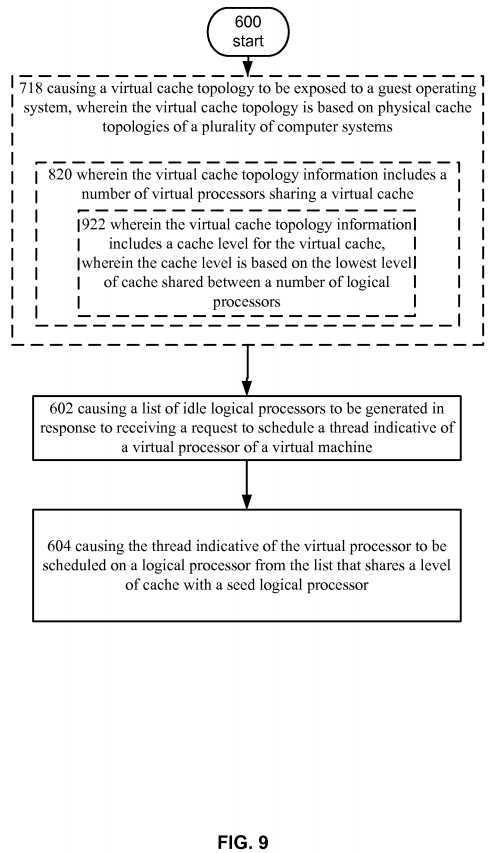
Turning now to?FIG. 6, it illustrates an operational procedure including operations?600,?602, and?604. Operation?600?begins the operational process and operation?602?illustrates causing a list of idle logical processors to be generated in response to receiving a request to schedule a thread indicative of a virtual processor of a virtual machine. For example, and turning to FIG. 5,?hypervisor?550?can be configured to instantiate and control virtual machine?530?and expose one or more virtual processors such as VP?534-VP540?to guest operating system?532. For example, a guest operating system can issue an instruction querying the virtual topology. This instruction can be intercepted by?hypervisor?550?and virtualized. As shown by the dashed lines for virtual L3 cache, in an example embodiment virtual processors?534-540?may be single core virtual processors and the virtual L3 cache may not exist. Or put another way, in this example, a virtualized topology may not be exposed to guest operating system?532. In this example, guest operating system?532?may schedule a thread on virtual processor?534?and?hypervisor?550?can receive a request to schedule virtual processor?534?on a logical processor. In response to receiving the request?scheduler?552?can execute and generate a list of idle logical processors. In an example embodiment?scheduler?552?could check an idle processor map and determine which processors in the system are idle.
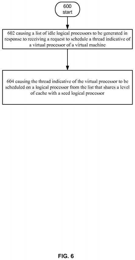
Turning to operation?604, it shows causing the thread indicative of the virtual processor to be scheduled on a logical processor from the list that shares a level of cache with a seed logical processor. Continuing with the example above, scheduler?552?can execute and schedule the thread on a logical processor that shares a level of cache with a seed logical processor. For example, in this example embodiment?scheduler?552?can attempt to schedule the thread on a logical processor that is close to a seed logical processor. In this example,?scheduler?552?can increase performance of virtual machine?530?by increasing the chance that the thread will use data or instructions that are in the shared cache and the logical processor can run without having to fetch data or instructions from RAM or another NUMA node.
Continuing from the specific example above,?scheduler?552?can determine that the seed for thread indicative of virtual processor?534?is logical processor?506. In the event that logical processor?506?is unavailable,?scheduler?552?can then be configured to access cache hierarchy table?556?and determine which idle logical processors share cache with logical processor?506.?Scheduler?552?can then be configured to select one of the logical processors that shares cache to run thread indicative of VP?534. For example, LP?508?and LP?514?may be idle.?Scheduler?552?can access cache hierarchy table556?and determine LP?508?shares L2 and L3 with LP?506?and LP?506?shares L3 cache with LP?514.?Scheduler?552?can then select one of the logical processors to run the thread.
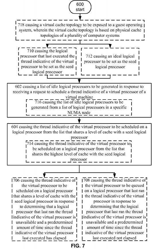
Turning now to?FIG. 7, it illustrates an alternative embodiment of the operational procedure of?FIG. 6?including the additional operations?706-718. Operation?706?shows causing the thread indicative of the virtual processor to be scheduled on a logical processor that shares a level of cache with the seed logical processor in response to determining that a logical processor that last ran the thread indicative of the virtual processor is unavailable and a predetermined amount of time since the thread indicative of the virtual processor last executed has elapsed. For example,?scheduler?552?may determine that the thread indicative of virtual processor?534?is associated with a latency sensitive workload. That is, the workload, e.g., the program executed by guest operating system?532, may need to be scheduled as soon as possible when the guest runs it on the virtual processor. For example,?hypervisor?550?may obtain performance information from guest?532?indicating that its performance is sluggish or guest OS?532?is performing a lot of network based input/output work. In another embodiment, an administrator or policy could set threads from virtual machine?530?as latency sensitive. Regardless of how the thread was identified as latency sensitive,?scheduler?552?can obtain information from thread table?560?when a request to schedule thread indicative of virtual processor?534?is received and determine how to schedule it.
In an example embodiment,?scheduler?552?can immediately schedule the thread, or queue it depending on when the thread last ran. For example, if the thread recently ran, there is a chance that information it would use is still in cache. In the instance where the information is still in cache, the performance hit due to queuing may be less than the performance hit due to having a cache miss. Alternatively, if thread has not run recently, then the cache may be cold, i.e., may not have any useful information, and no performance benefits would be obtained by waiting any longer.
In this example, a predetermined threshold time can be used to determine that the thread should be run. For example, scheduler?552?can receive a request to schedule virtual processor?534.?Scheduler?552?can run and access thread table?560to obtain information regarding virtual processor?534?such as information that describes that the thread is latency sensitive, a time that thread last ran, and the logical processor that last ran thread indicative of virtual processor?534.?Scheduler?552can access an idle processor map and check to see what logical processors are available. In this specific example, the logical processor that last ran the thread, e.g., LP?506, may be unavailable. In this situation,?scheduler?552?can compare the amount of time since virtual processor?534?last ran to a predetermined threshold and determine that the amount of time since it last ran is greater than the predetermined value. Schedule?552?can be scheduled to access cache hierarchy table556?and determine which available logical processors share cache with logical processor?506?and select one to run thread534.
Continuing with the description of?FIG. 7, operation?708?shows causing the thread indicative of the virtual processor to be queued on a logical processor that last ran the thread indicative of the virtual processor in response to determining that the logical processor that last ran the thread indicative of the virtual processor is unavailable and a predetermined amount of time since the thread indicative of the virtual processor last executed not elapsed. Similar to operation?706, thread indicative of virtual processor?534?could be a latency sensitive thread. In this example,?scheduler?552?can be configured to queue thread?534?on logical processor?506?in the instance that logical processor?506?is unavailable and the predetermined amount of time has not elapsed. In this example, a decision can be made that the savings do to obtaining cache hits will offset the fact that the latency sensitive thread is not executed as soon as possible. As stated above, the predetermined threshold can be set based on performance characteristics of the system and may be adjusted by an administrator or a policy.
Operation?710?of?FIG. 7?shows causing the logical processor that last executed the thread indicative of the virtual processor to be set as the seed logical processor. For example, in an embodiment an administrator or a policy can be used by hypervisor?550?to set a seed logical processor for a virtual processor. In a specific example, the logical processor that last ran virtual processor?534?can be set as the seed. Thus, in this example embodiment, if thread?534?is moved from logical processor?506?to logical processor?508, the seed can be changed in thread table?560?to reflect that the seed is now logical processor?508. In this example, virtual machine?530?may be a single core virtual machine?530?and the only efficiency that can be obtained from cache hits is from configuring virtual processor?534?to share as many caches with the logical processor that last ran it.
Turning to operation?712, it shows causing an ideal logical processor to be set as the seed logical processor. For example, and turning to?FIG. 5, an ideal logical processor can be set as the seed. In this example, the seed could be statically assigned at boot based on a policy or by an administrator. In this example, the seed can remain constant even if threads indicative of virtual processors are moved by?scheduler?552. For example, virtual machine?530?can be instantiated. A policy could be read by?hypervisor?550?that directs it to set ideal processors for virtual processors?534-540. In response, hypervisor?550?can assign logical processor?506?as the ideal for virtual processor?534, logical processor?508?as the ideal for virtual processor?536?and so on and so forth. This information can then be recorded in thread table?560. In the event that virtual processor?534?is moved the next time it runs?scheduler?552?can be configured to access thread table?560; determine that LP?506?is set as an ideal LP; and check to see if LP?506?is free. In this example, if LP?506?is free it is scheduled thereon regardless of the identity of the last LP that ran VP?534. If it unavailable,?scheduler?552?attempts to locate it as close as possible to the ideal LP.
Turning to operation?714, it shows causing the thread indicative of the virtual processor to be scheduled on a logical processor from the list that shares the highest level of cache with the seed logical processor. For example, in an example scheduler?552?can be configured to attempt to collocate virtual processors such that they share the highest level of cache. In this example, guest?532?has the best chance of seeing a performance increase due to cache hits. As described above, each logical processor can have arrays associated therewith stored in cache hierarchy table?556. In response to receiving a request to schedule a thread indicative of a VP, such as VP?534,?scheduler?552?can determine the seed for VP?534?and access cache hierarchy table?556?to determine the available LP that shares the highest level of cache with the seed. Scheduler?552?can then schedule the thread on an available LP that shares the highest level of cache with the seed.
Turning to operation?716, it shows causing the list of idle logical processors to be generated from a list of logical processors in a specific NUMA node.?Hypervisor?550?can be configured to maintain idle processor maps for each NUMA node in the computer system. In this example, each virtual processor could be assigned an ideal NUMA node when virtual machine?530is started and this information could be stored in thread table?560. When?scheduler?552?runs it can determine that a thread has been assigned an ideal NUMA node and?scheduler?552?can generate the list of idle processors from an idle processor map associated with the ideal NUMA node. In this way the initial set of possible logical processor candidates is reduced. In a specific example, NUMA node?500?could be the ideal NUMA node for thread indicative of virtual processor?534.?Scheduler552?can obtain this information from thread table?560; access idle processor map?554; and generate a list of idle processors in NUMA node?500.
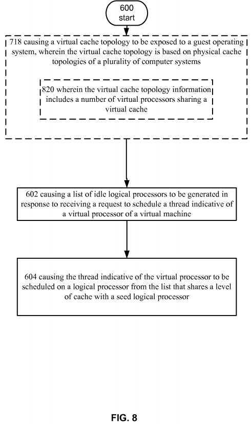
Continuing with the description of?FIG. 7, operation?718?shows causing a virtual cache topology to be exposed to a guest operating system, wherein the virtual cache topology is based on physical cache topologies of a plurality of computer systems. For example, and turning to?FIG. 5,?hypervisor?550?can obtain configuration information that describes how to generate a virtual cache topology for virtual machine?530. In an embodiment,?hypervisor?550?can generate the information or, in a datacenter embodiment, it can receive the configuration information from, for example, management system?402?ofFIG. 4. The configuration information can describe a virtual cache topology that can be exposed to guest operating system532?when it boots. Guest operating system?532?can then detect the topology and configure it‘s?scheduler?to depend on it. For example, guest operating system?532?can query the hardware to determine the topology.?Hypervisor?550?can intercept the query and respond with virtualized information that describes the virtual cache topology. In this example, the virtual cache topology can be independent from the physical topology of the host computers system so that guest operating system?532?can be easily migrated to any computer system in datacenter?400.
Turning now to?FIG. 8, it illustrate an alternative embodiment of the operational procedure depicted in?FIG. 7.?FIG. 8includes a refinement?820?of operation?718, wherein the virtual cache topology information includes a number of virtual processors sharing a virtual cache. For example,?hypervisor?500?or management system?402?of datacenter?400?can be configured to generate the virtual cache topology exposed to guest operating system?532. The virtual cache topology can include a calculated number of virtual processors that share a virtual cache. In an example, the number of processors can be determined by calculating the greatest common divisor of logical processors that share a lowest level of cache for each NUMA node in datacenter?400. For example, each computer system can have a topology the same as the physical topology described in?FIG. 5?and management system?402?can be configured to determine the lowest level of cache in each NUMA node, e.g., L3 cache in this example, and determine the number of logical processors in each NUMA node that shares this level of cache, i.e., 6 in NUMA node?500?and 4 in NUMA node?502. Management system?402?can then determine that the greatest common divisor between 6 and 4 is 2. This value can be set as the number of virtual processors that share a level of cache in the virtual cache topology.
In another example, the number of virtual processors that share a level of cache in the virtual cache topology can be calculated using a different technique. For example, management system?402?can determine the number of logical processors that share a highest level of cache in each NUMA node. Management system?402?can then set the smallest number of logical processors as the number of virtual processors that share a level of cache in the virtual cache topology. For example, management?402?can receive information that describes that L2 is the highest cache shared by logical processors?506-512, L2 is the highest cache shared between logical processors?514-516, and L3 is the highest level of cache shared between logical processors?518-524. Management system?402?can then determine that 4, 2, and 4, logical processors share respective highest levels of cache in the computer systems in, for example datacenter?400. In this example embodiment management system?402?can select the smallest number (2) and set it as the number of virtual processors that share a level of cache in the virtual cache topology.
Turning now to?FIG. 9, shown is refinement?922?of operation?820, wherein the virtual cache topology information includes a cache level for the virtual cache, wherein the cache level is based on the lowest level of cache shared between a number of logical processors. For example, after the number of virtual processors for the virtual cache topology is determined, the type of virtual cache that is shared can be determined. In an example embodiment the lowest type of cache shared by a number of logical processors equal to or greater to the determined number of virtual processors can be used as the virtual cache.
For example, are referring to?FIG. 5, management system?402?can be configured to receive information describing that NUMA node?500?includes an L2 cache that is shared between 4 logical processors, an L2 cache shared between 2 logical processors, and an L3 cache shared between 6 logical processors. Management system?402?can also receive information that describes that NUMA node?502?includes an L3 cache shared between 4 logical processors. In this example, management system?402?can determine that NUMA node?500?can support an L2 and L3 cache shared between a number of logical processors equal or greater than the number of virtual processors set for the virtual cache topology. Management system?402?can also determine that NUMA node?502?can support an L3 cache shared between a number of logical processors equal or greater than the number of virtual processors set for the virtual cache topology. Management system402?can select L3 as the cache to expose in virtual cache topology because it is the lowest cache that can be honored by each NUMA node.
Turning now to?FIG. 10, it illustrates an operational procedure including operations?1000,?1002,?1004,?1006, and?1008. Operation?1000?begins the operational procedure and operation?1002?shows exposing a plurality of single core virtual processors to a virtual machine. For example, and turning to?FIG. 5, a computer system can execute instructions indicative of?hypervisor?550?and can load instructions operable to instantiate virtual machine?530.?Hypervisor?550?can set up virtual machine?530?to include a plurality of virtual processors such as virtual processors?534-540. In this example, the virtual processors can be single core VPs. Put another way, the virtual processors?534-540?may not share caches. Guest operating system?532?can boot and detect the single cored virtual processors by querying the virtual topology.?Hypervisor550?can intercept the query and return a virtualized topology including a plurality of single core virtual processors.
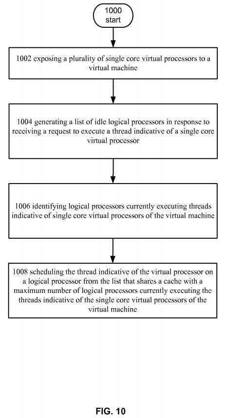
Continuing with the description of?FIG. 10, operation?1004?shows generating a list of idle logical processors in response to receiving a request to execute a thread indicative of a single core virtual processor. For example, an executing instance of hypervisor?550?can be set to generate a list of idle logical processors in the event that it receives a request to schedule a thread indicative of a virtual processor such as virtual processor?540. For example, executable instructions of?scheduler?552can be loaded into memory that set up idle processor maps for the logical processors in a computer system and?hypervisorcan be configured to run?scheduler?552, which can generate a list of idle logical processors, in response to receiving a thread from a guest such as guest operating system?532.
Turning now to operation?1006, it shows identifying logical processors currently executing threads indicative of single core virtual processors of the virtual machine. Continuing with the example, in response to a request to run a thread indicative of a virtual processor, such as VP?540,?hypervisor?550?can determine where threads indicative of the virtual processors of the VM are currently executing. For example, each time a logical processor runs it can update thread table?560?with information that identifies which virtual processor it is running. When?hypervisor?550?runs, it can check thread table?560?and see what logical processors are currently running virtual processors for the virtual machine. For example, virtual processor?534?can be executing on logical processor?514, virtual processor?536?can be executing on LP?516, and virtual processor?538?can be executing on virtual processor?512.
Turning now to operation?1008, it shows scheduling the thread indicative of the virtual processor on a logical processor from the list that shares a cache with a maximum number of logical processors currently executing the threads indicative of the single core virtual processors of the virtual machine. For example,?scheduler?552?can determine which idle logical processor shares a cache the maximum number of logical processors currently running threads indicative of the other VPs in the virtual machine. For example,?scheduler?552?can access cache hierarchy table?556, which can include an array of bitmaps for each logical processor, and determine which of the available processors shares a cache with the max number of LPs. Continuing with the example from above,?scheduler?552?can schedule thread indicative of virtual processor?540?on logical processor506?since logical processor?506?shares cache with the maximum number of currently executing virtual processors.
Turning now to?FIG. 11, it shows an alternative embodiment of the operational procedure of?FIG. 10?including operations1110?and?1112. Operation?1110?shows generating the list of idle logical processors from a list of logical processors in a non-uniform memory architecture (NUMA) node, wherein each NUMA node in a computer system is associated with a unique list of logical processors in the NUMA node. For example,?scheduler?552?can be configured to schedule the thread on a logical processor that shares a highest level of cache with a maximum amount of virtual processors currently running. For example, in an embodiment?scheduler?552?may determine that there are multiple available logical processors that share cache with a maximum number of logical processors. In this example,?scheduler?552?can be configured to select the logical processor that shares the highest cache with the most logical processors. For example, in an embodiment logical processors?508-514?may be running?4?virtual processors of a virtual machine including 5 virtual processors.?Scheduler?552may determine that LP?506?and LP?516?are available and each share L3 cache with the logical processors currently running virtual processors of the virtual machine. In this example?scheduler?552?can determine that logical processor?506?shares L2 cache with 3 of the 4 logical processors and LP?516?shares L2 cache with 1 logical processor. In this example?scheduler552?can select logical processor?506.
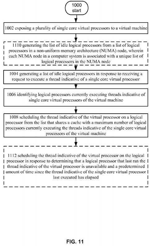
Continuing with the description of?FIG. 11, operation?1112?shows scheduling the thread indicative of the virtual processor on the logical processor in response to determining that a logical processor that last ran the thread indicative of the virtual processor is unavailable and a predetermined amount of time since the thread indicative of the single core virtual processor last executed has elapsed. For example,?scheduler?552?may determine that the thread is associated with a latency sensitive workload. That is, the workload, e.g., the programs executed by guest operating system?532, may need to be scheduled as soon as possible when it is received by?scheduler?552. In this example, if a predetermined amount of time since the VP last ran has elapsed, schedule?552?can be scheduled to access cache hierarchy table?556?and determine which available logical processors share cache with, for example, the logical processor that last ran it or one that shares a cache with a maximum number of logical processors currently executing virtual processors of the virtual machine.
Turning now to?FIG. 12, it illustrates a operational procedure including operations?1200,?1202,?1204, and?1206. Operation1200?begins the procedure and operation?1202?shows causing a thread indicative of a virtual processor of a virtual machine to be assigned a distinct logical processor to execute thereon. In an embodiment,?hypervisor?550?can assign each virtual processor of a virtual machine a distinct logical processor. In this example, when a request to schedule the virtual processor is received,?hypervisor?550?can attempt to schedule the virtual processor on the assigned logical processor. For example, thread table?560?can store information that identifies the assigned logical processor.?Scheduler?552?can check thread table560?when it receives a request to schedule a thread.
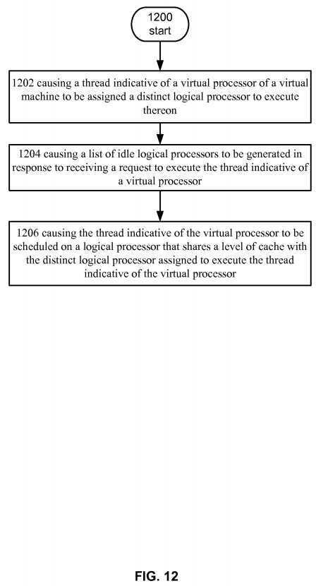
Continuing with the description of?FIG. 12, operation?1204?shows causing a list of idle logical processors to be generated in response to receiving a request to execute the thread indicative of a virtual processor. For example, an executing instance of?hypervisor?550?can be set to generate a list of idle logical processors in the event that it receives a request to schedule a thread indicative of a virtual processor such as virtual processor?540. For example, executable instructions of?scheduler?552can be loaded into memory that set up idle processor maps for the logical processors in a computer system and?hypervisor can be configured to run?scheduler?552, which can generate a list of idle logical processors, in response to receiving a thread from a guest such as guest operating system?532.
Turning back again to?FIG. 12, operation?1206?shows causing the thread indicative of the virtual processor to be scheduled on a logical processor that shares a level of cache with the distinct logical processor assigned to execute the thread indicative of the virtual processor. For example,?scheduler?552?can determine which idle logical processors share a cache with the assigned logical processor and select one. For example,?scheduler?552?can access cache hierarchy table?556, which can include an array of bitmaps for each logical processor, and determine which of the available processors shares a cache with assigned logical processor.
Referring now to?FIG. 13, it illustrate an alternative embodiment of the operational procedure illustrated in?FIG. 12?including the additional operations?1308,?1310,?1312,?1314,?1316, and?1318. Operation?1308?shows causing the logical processor that shares the level of cache with the distinct logical processor to be selected in response to determining that the distinct logical processor is unavailable. For example,?scheduler?552?can be configured to attempt to schedule thread indicative of a virtual processor on the assigned logical processor. In the event that the processor is unavailable, it can schedule the thread indicative of the virtual processor on a logical processor that shares a level of cache with a logical processor assigned to execute the thread indicative of the virtual processor.
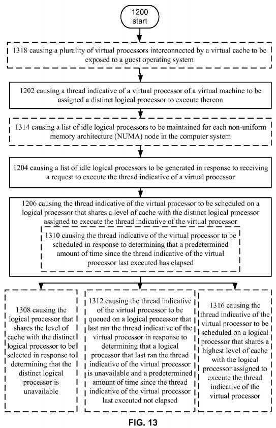
Operation?1310?shows causing the thread indicative of the virtual processor to be scheduled in response to determining that a predetermined amount of time since the thread indicative of the virtual processor last executed has elapsed. For example, in an embodiment?scheduler?552?can be configured to locate a logical processor to run a latency sensitive workload. That is, the workload, e.g., the programs executed by guest operating system?532, may need to be scheduled as soon as possible when it is received by?scheduler?552. In this example, if a predetermined amount of time since the VP last ran has elapsed, schedule?552?can be scheduled to access cache hierarchy table?556?and determine which available logical processors share cache with, for example, the assigned logical processor.
Operation?1312?shows causing the thread indicative of the virtual processor to be queued on a logical processor that last ran the thread indicative of the virtual processor in response to determining that a logical processor that last ran the thread indicative of the virtual processor is unavailable and a predetermined amount of time since the thread indicative of the virtual processor last executed not elapsed. In an embodiment, thread indicative of virtual processor?534?could be a latency sensitive thread. In this example,?scheduler?552?can include instructions for queuing the thread in the instance that logical processor?506?is unavailable and the predetermined amount of time has not elapsed. In this example, a decision can be made that the savings do to having cache hits will offset the fact that the latency sensitive thread is not executed as soon as possible. As stated above, the predetermined threshold can be set based on performance characteristics of the system and may be adjusted by an administrator or a policy.
Operation?1314?shows causing a list of idle logical processors to be maintained for each non-uniform memory architecture (NUMA) node in the computer system. For example,?hypervisor?550?can be configured to maintain idle processor maps for each NUMA node in the computer system. In this example, the NUMA node that includes the assigned processors can be set as the node that?scheduler?552?first checks in response to receiving a request to schedule a thread. When?scheduler552?runs, it can generate the list of idle processors from an idle processor map associated with NUMA node. In this way the initial set of possible logical processor candidates is reduced without having to check a bitmap listing every logical processor in the computer system.
Operation?1316?shows causing the thread indicative of the virtual processor to be scheduled on a logical processor that shares a highest level of cache with the logical processor assigned to execute the thread indicative of the virtual processor. For example,?scheduler?552?can be configured to attempt to collocate virtual processors such that they share the highest level of cache. In this example, guest?532?has the best chance of seeing a performance increase due to cache hits. As described above, each logical processor can have arrays associated therewith stored in cache hierarchy table?556. In response to receiving a request to schedule a thread indicative of a VP, such as VP?534,?scheduler?552?can determine the seed for VP?534?and access cache hierarchy table?556?to determine the available LP that shares the highest level of cache with the assigned logical processor.?Scheduler?552?can then schedule the thread on an available LP that shares the highest level of cache with the assigned logical processor.
Operation?1318?shows causing a plurality of virtual processors interconnected by a virtual cache to be exposed to a guest operating system. For example, and turning to?FIG. 5,?hypervisor?550?can obtain configuration information that describes how to generate a virtual cache topology for virtual machine?530. In an embodiment,?hypervisor?550?can generate the information or, in a datacenter embodiment, it can receive the configuration information from, for example, management system?402?of?FIG. 4. The configuration information can describe a virtual cache topology that can be exposed to guest operating system?532?when it boots. Guest operating system?532?can then detect the topology and configure it‘s?scheduler to depend on it. For example, guest operating system?532?can query the virtual processors to determine the topology. Hypervisor?550?can intercept the query and respond with topology information that describes the virtual cache topology. In this example, the virtual cache topology can be independent from the physical topology of the host computers system so that guest operating system?532?can be easily migrated to any computer system in datacenter?400.
SRC=https://www.google.com.hk/patents/US20130268933
标签:des style blog http color os io ar strong
原文地址:http://www.cnblogs.com/coryxie/p/3961762.html