标签:des style blog http color os io ar strong
In one embodiment, a method includes transitioning control to a virtual machine (VM) from a virtual machine monitor (VMM), determining that a?VMM?timer indicator is set to an enabling value, and identifying a?VMM?timer?value configured by the?VMM. The method further includes periodically comparing a current value of a timing source with the?VMM?timer?value, generating an internal event if the current value of the timing source has reached the?VMM?timer?value, and transitioning control to the?VMM?in response to the internal event without incurring an event handling procedure in any one of the?VMM?and the VM.
Embodiments of the invention relate generally to virtual machines, and more specifically to providing support for a?timer?associated with a virtual machine monitor.
Timers and time reference sources are typically used by operating systems and application software to schedule and optimize activities. For example, an operating system kernel may use a?timer?to allow a plurality of user-level applications to time-share the resources of the system (e.g., the central processing unit (CPU)). An example of a?timer?used on a personal computer (PC) platform is the 8254 Programmable Interval?Timer. This?timer?may be configured to issue interrupts after a specified interval or periodically.
An example of a time reference source is the timestamp counter (TSC) used in the instruction set architecture (ISA) of the Intel? Pentium? 4 (referred to herein as the IA-32 ISA). The TSC is a 64-bit counter that is set to 0 following the hardware reset of the processor, and then incremented every processor clock cycle, even when the processor is halted by the HLT instruction. The TSC cannot be used to generate interrupts. It is a time reference only, useful to measure time intervals. The IA-32 ISA provides an instruction (RDTSC) to read the value of the TSC and an instruction (WRMSR) to write the TSC. When WRMSR is used to write the timestamp counter, only the 32 low-order bits may be written; the 32 high-order bits are cleared to 0.
In a virtual machine system, a virtual-machine monitor (VMM) may need to utilize platform-based timers in a manner similar to that of a conventional operating system. For example, a?VMM?may use timers to schedule resources, assure security, provide quality of service, etc.
The present invention is illustrated by way of example, and not by way of limitation, in the figures of the accompanying drawings and in which like reference numerals refer to similar elements and in which:
FIG. 1?illustrates one embodiment of a virtual-machine environment, in which the present invention may operate;
FIG. 2?is a flow diagram of one embodiment of a process for providing support for a?timer?associated with a?VMM;
FIGS. 3 and 4?are flow diagrams of two embodiment of a process for utilizing a VMM timer to decide whether to return control to a?VMM; and
FIG. 5?is a flow diagram of one embodiment of a process for configuring a?timer associated with a?VMM.
A method and apparatus for providing support for a?timer?associated with a virtual machine monitor is described. In the following description, for purposes of explanation, numerous specific details are set forth in order to provide a thorough understanding of the present invention. It will be apparent, however, to one skilled in the art that the present invention can be practiced without these specific details.
FIG. 1?illustrates one embodiment of a virtual-machine environment?100, in which the present invention may operate. In this embodiment, bare platform hardware116?comprises a computing platform, which may be capable, for example, of executing a standard operating system (OS) or a virtual-machine monitor (VMM), such as a?VMM?112.
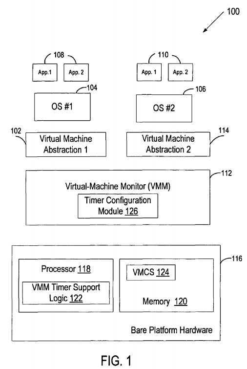
The?VMM?112, though typically implemented in software, may emulate and export a bare machine interface to higher level software. Such higher level software may comprise a standard or real-time OS, may be a highly stripped down operating environment with limited operating system functionality, may not include traditional OS facilities, etc. Alternatively, for example, the?VMM?112?may be run within, or on top of, another?VMM. VMMs may be implemented, for example, in hardware, software, firmware or by a combination of various techniques.
The platform hardware?116?can be of a personal computer (PC), mainframe, handheld device, portable computer, set-top box, or any other computing system. The platform hardware?116?includes a processor?118?and memory?120.
Processor?118?can be any type of processor capable of executing software, such as a microprocessor, digital signal processor, microcontroller, or the like. The processor?118?may include microcode, programmable logic or hardcoded logic for performing the execution of method embodiments of the present invention. Although?FIG. 1?shows only one such processor?118, there may be one or more processors in the system.
Memory?120?can be a hard disk, a floppy disk, random access memory (RAM), read only memory (ROM), flash memory, any combination of the above devices, or any other type of machine medium readable by processor?118. Memory?120may store instructions and/or data for performing the execution of method embodiments of the present invention.
The?VMM?112?presents to other software (i.e., "guest" software) the abstraction of one or more virtual machines (VMs), which may provide the same or different abstractions to the various guests.?FIG. 1?shows two VMs,?102?and?114. The guest software running on each VM may include a guest OS such as a guest OS104?or?106?and various guest software applications?108?and?110. Each of the guest OSs?104?and?106?expects to access physical resources (e.g., processor registers, memory and I/O devices) within the VMs?102?and?114?on which the guest OS?104?or?106?is running and to perform other functions. For example, the guest OS?104?or?106?expects to have access to all registers, caches, structures, I/O devices, memory and the like, according to the architecture of the processor and platform presented in the VM?102?and?114. The resources that can be accessed by the guest software may either be classified as "privileged" or "non-privileged." For privileged resources, the?VMM?112?facilitates functionality desired by guest software while retaining ultimate control over these privileged resources. Non-privileged resources do not need to be controlled by the?VMM112?and can be accessed by guest software.
Further, each guest OS expects to handle various fault events such as exceptions (e.g., page faults, general protection faults, etc.), interrupts (e.g., hardware interrupts, software interrupts), and platform events (e.g., initialization (NIT) and system management interrupts (SMIs)). Some of these fault events are "privileged" because they must be handled by the VMM?112?to ensure proper operation of VMs?102?and?114?and for protection from and among guest software.
When a privileged fault event occurs or guest software attempts to access a privileged resource, control may be transferred to the?VMM?112. The transfer of control from guest software to the?VMM?112?is referred to herein as a VM exit. After facilitating the resource access or handling the event appropriately, the?VMM?112?may return control to guest software. The transfer of control from the?VMM?112?to guest software is referred to as a VM entry.
In one embodiment, the processor?118?controls the operation of the VMs?102?and?114?in accordance with data stored in a virtual machine control structure (VMCS)?124. The VMCS?124?is a structure that may contain the state of guest software, the state of the?VMM?112, execution control information indicating how the?VMM?112?wishes to control operation of guest software, information controlling transitions between the?VMM?112?and a VM, etc. The processor?118?reads information from the VMCS?124?to determine the execution environment of the VM and to constrain its behavior. In one embodiment, the VMCS is stored in memory?120. In some embodiments, multiple VMCS structures are used to support multiple VMs.
In one embodiment, when a VM exit occurs, components of the processor state used by guest software are saved, components of the processor state required by the?VMM?112?are loaded, and the execution resumes in the?VMM?112. In one embodiment, the components of the processor state used by guest software are stored in a guest-state area of VMCS124?and the components of the processor state required by the?VMM?112?are stored in a monitor-state area of VMCS?124. In one embodiment, when a transition from the?VMM?112?to guest software occurs, the processor state that was saved at the VM exit (and may have been modified by the?VMM?112?while processing the VM exit) is restored and control is returned to the VM?102?or?114.
An event causing a VM exit may or may not require the execution of an "event handling" procedure. The event handling procedure refers to event reporting that changes control flow of the code executing on the processor even though no branches requiring such a change exist in the code. Event reporting is typically performed when an event is an exception or an interrupt and may require saving the state of the running code (e.g., on a stack), locating an interrupt vector by traversing a redirection structure (e.g., the interrupt descriptor table (IDT) in the instruction set architecture (ISA) of the Intel? Pentium? 4 (referred to herein as the IA-32 ISA)), loading the state of the event handler, and starting execution in the new code. When an exception or interrupt occurs during the operation of the VM?102?or?114, and this exception or interrupt should be handled by the?VMM?112?(e.g., an I/O completion interrupt for an I/O operation that was not initiated by or on behalf of the running VM?102?or?114), the event handling procedure is executed after exiting the running VM?102?or?114?(i.e., transitioning control to the?VMM?112).
Some events do not require the above-referenced event handling procedure to be executed in either the?VMM?112?or the VM?102?or?114. Such events are referred to herein as internal events. For example, the VM?102?or?114?may incur a page fault on a page, which the?VMM?112?has paged out but the VM?102?or?114?expects to be resident. Such a page fault cannot cause the event handling procedure, in order to prevent a violation of virtualization. Instead, this page fault is handled using a VM exit, which causes the VM state to be saved in the VMCS?124, with the execution resuming in the?VMM?112, which handles the page fault and transitions control back to the VM?102?or?114.
The?VMM?112?may need to gain control during the operation of the VM?102?or?114?to schedule resources, provide quality of service, assure security, and perform other functions. Hence, the?VMM?112?needs to have a?timer?mechanism allowing the VMM?112?to indicate the desired time for gaining control. In one embodiment, the?VMM?112?includes a?timer?configuration module?126?that provides values for fields associated with the?VMM?timer?prior to requesting a transition of control to the VM?102?or?114. These fields may include, for example, a?VMM?timer?indicator specifying whether a?VMM?timer?should be enabled, and a?VMM?timer?value field indicating a desired time for regaining control.
In one embodiment, the?VMM?timer?indicator and the?VMM?timer?value are stored in the VMCS?124. Alternatively, the?VMM timer?indicator and the?VMM?timer?value may reside in the processor?118, a combination of the memory?120?and the processor?118, or in any other storage location or locations. In one embodiment, a separate pair of the?VMM?timer?indicator and?VMM?timer?value is maintained for each of the VMs?102?and?114. Alternatively, the same?VMM?timer?indicator and VMM?timer?value are maintained for both VMs?102?and?144?and are updated by the?VMM?112?before each VM entry.
In one embodiment, in which the system?100?includes multiple processors or multi-threaded processors, each of the logical processors is associated with a separate pair of the?VMM?timer?indicator and?VMM?timer?value, and the?VMM?112configures the?VMM?timer?indicator and?VMM?timer?value for each of the logical processors.
In one embodiment, the processor?118?includes?VMM?timer?support logic?122?that is responsible for determining whether the?VMM?timer?is enabled based on the?VMM?timer?indicator. If the?VMM?timer?is enabled, the?VMM?timer?support logic?122decides when to transition control to the?VMM?112?using the?VMM?timer?value specified by the?VMM?112.
In one embodiment, the?VMM?timer?value specifies the time at which control should be returned to the?VMM?112. During the operation of the VM?102?or?114, the?VMM?timer?support logic?122?periodically (e.g., after each cycle executed by the currently operating VM?102?or?114) compares the current value of the timing source with the?VMM?timer?value specified by the?VMM?112. The timing source may be any clock used by the system?100?to measure time intervals. For example, in the IA-32 ISA, the timing source used for measuring time intervals may be the timestamp counter (TSC).
When the current time provided by the timing source "reaches" the?VMM?timer?value specified by the?VMM?112, the?VMM timer?support logic?122?transitions control to the?VMM?112, indicating that the cause of the transition is the?VMM?timer. The current time "reaches" the?VMM?timer?value if the current time matches the?VMM?timer?value or exceeds the?timer?value (when an exact match between the current time and the?VMM?timer?value is not possible).
In another embodiment, the?VMM?timer?value specifies the time interval at the end of which the?VMM?112?should gain control. During the operation of the VM?102?or?114, the?VMM?timer?support logic?122?uses this time interval as a countdown value, periodically decrementing it (e.g., every N ticks of the clock). When the countdown value reaches zero, the?VMM timer?support logic?122?transitions control to the?VMM?112. In one embodiment, if a VM exit occurs prior to the expiration of the countdown value (e.g. due to a fault detected during the operation of the VM), the?VMM?timer?support logic?122?stores a current countdown value to the VMCS?124. The stored countdown value may replace the?VMM?timer?value previously specified by the?VMM?112?or be maintained in a designated countdown value field.
FIG. 2?is a flow diagram of one embodiment of a process?200?for providing support for a?timer?associated with a?VMM. The process may be performed by processing logic that may comprise hardware (e.g., circuitry, dedicated logic, programmable logic, microcode, etc.), software (such as that run on a general purpose computer system or a dedicated machine), or a combination of both. In one embodiment, process?200?is performed by?VMM?timer?support logic?122?of?FIG. 1.
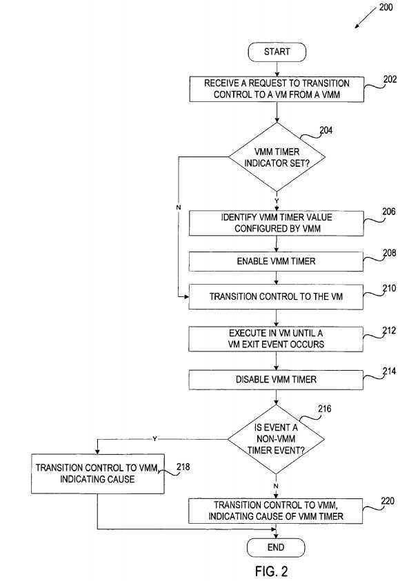
Referring to?FIG. 2, process?200?begins with processing logic receiving a request to transition control to a VM from a?VMM (i.e., the request for VM entry) (processing block?202). In one embodiment, the VM entry request is received via a VM entry instruction executed by the?VMM.
Next, processing logic determines whether a?VMM?timer?indicator is set to an enabling value (processing box?204). The VMM?timer?indicator is configured by the?VMM?and may be set to the enabling value to indicate that the?VMM?timer mechanism is enabled. As discussed above, the?VMM?timer?mechanism (also referred to herein as the?VMM?timer) allows the?VMM?to gain control at a specific point of time during the operation of the VM.
If the determination made at processing box?204?is negative (the?VMM?timer?indicator is set to a disabling value), processing logic proceeds to processing box?210.
If the determination made at processing box?204?is positive, processing logic identifies a?VMM?timer?value configured by the VMM?(processing block?206). In one embodiment, processing logic identifies the?VMM?timer?value by retrieving it from the VMCS. The?VMM?stores the?VMM?timer?value to the VMCS prior to issuing a VM entry request. At processing block?208, processing logic configures and enables the?VMM?timer?using the?VMM?timer?value.
In one embodiment, the?VMM?timer?value specifies the time at which control should be returned to the?VMM. The?VMM?may calculate this?timer?value by adding an offset value (i.e., a time interval specifying how long the VM is allowed to execute) to the value of the timing source read by the?VMM?at the time of calculation. In another embodiment, the?VMM?timer?value is an offset time interval specifying how long the VM is allowed to execute.
Next, processing logic transitions control to the VM (processing block?210) and allows the VM to execute until an event associated with a VM exit occurs (processing block?212). In one embodiment, an event is associated with a VM exit if an execution control indicator associated with this event is set to a VM exit value to cause a VM exit for this event.
At processing block?214, the?VMM?timer?is disabled. Note that if the?VMM?timer?was not enabled in processing box?208, this processing step is not required. Next, if the event is a non-VMM?timer?event (e.g., a fault) associated with a VM exit (processing block?216), processing logic returns control to the?VMM, indicating the cause of the VM exit (processing block218).
Alternatively, if the event is caused by the?VMM?timer?(processing block?216), processing logic transitions control to the VMM, indicating that the VM exist was caused by the?VMM?timer?(processing block?220).
The?VMM?timer?will generate events to trigger a VM exit based on the?VMM?timer?value specified by the?VMM. In one embodiment, in which the?VMM?timer?value specifies the time at which the?VMM?desires to gain control, processing logic makes the above decision by periodically comparing the current time of the clock (e.g., the TSC, or some other timing reference) with the?VMM?timer?value until detecting that the clock reaches the?VMM?timer?value. In another embodiment, in which the?VMM?timer?value is an offset time value specifying how long the VM is allowed to execute, processing logic makes the above decision by periodically decrementing the offset time value until detecting that the offset time value reaches 0.
It should be noted that?FIG. 2?illustrates an embodiment in which VM exits caused by non-VMM?timer?events may have higher priority than VM exits caused by the?VMM?timer. However, this prioritization may be different depending on a prioritization scheme being used, and, therefore, a decision pertaining to a VM exit caused by a non-VMM?timer?event can be made after a decision pertaining to a VM exit caused by the?VMM?timer?(processing block?214). Additionally, some non-VMM?timer?events may have higher priority while other non-VMM?timer?events may have lower priority than the?VMM?timer event.
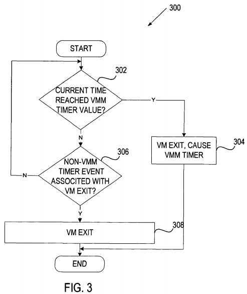
FIGS. 3 and 4?are flow diagrams of two embodiment of a process for utilizing a?VMM?timer?to decide whether to return control to a?VMM. The process may be performed by processing logic that may comprise hardware (e.g., circuitry, dedicated logic, programmable logic, microcode, etc.), software (such as that run on a general purpose computer system or a dedicated machine), or a combination of both. In one embodiment, the process is performed by?VMM?timer?support logic?122?of?FIG. 1.
Referring to?FIG. 3, process?300?uses a?VMM?timer?value that specifies the time at which control should be returned to the VMM. As discussed above, the?VMM?may calculate this?timer?value by adding an offset value (i.e., a time interval specifying how long the VM is allowed to execute) to the value of the timing source read by the?VMM?at the time of calculation.
Process?300?begins subsequent to determining that the?VMM?timer?is enabled, identifying a?VMM?timer?value configured by the?VMM, and transitioning control to the VM, as illustrated in?FIG. 2.
Initially, processing logic determines, during the operation of the VM, whether the current time provided by the timing source has reached the?VMM?timer?value (processing box?302). As discussed above, the timing source may be any clock used by the system?100?to measure time intervals. For example, a processor supporting the IA-32 ISA may use the TSC to measure time intervals.
In an embodiment, not all of the bits in the timing source may be compared to the?VMM?timer?value. Instead, only the high-order bits may be compared. The number of the bits compared is referred to as the?VMM-timer-comparator length. In an embodiment, the?VMM?may determine the?VMM-timer-comparator length by reading a capability model specific register (MSR) using the RDMSR instruction. In one embodiment, in which the TSC is used as the timing source, the determination of processing block?302?is made by comparing the high-order bits of the TSC with the same high-order bits of the?VMM timer?value, and if the TSC value is greater than or equal to the?VMM?timer?value, then the comparison in processing block302?is satisfied.
If the current time of the timing source reaches the?VMM?timer?value, processing logic creates an internal event and generates a VM exit, indicating that the cause of the VM exit is due to the?VMM?timer?(processing block?304). As discussed above, because the VM exit is caused by an internal event, the execution will resume in the?VMM?without performing the event handling procedure that is typically performed for interrupts or exceptions after exiting the VM.
If the current time of the timing source has not yet reached the?VMM?timer?value, processing logic checks for a non-VMM timer?event associated with a VM exit (processing box?306). If such event occurs, processing logic generates a VM exit and indicates the source of the VM exit (processing block?308). Otherwise, processing logic returns to processing block?302. Depending on the nature of the non-VMM?timer?event (e.g., whether the non-VMM?timer?event is an external interrupt or an internal event), exiting the VM may or may not be followed by the event handling procedure.
In one embodiment, the comparison between the current time and the?VMM?timer?value (illustrated in processing box?302) is performed after each cycle executed by the VM, until the current time meets or exceeds the?VMM?timer?value.
In an embodiment, the comparison is performed in a hardware component, which is configured to generate a signal if the current time matches the?VMM?timer?value. The signal indicates that a VM exit should be generated due to the?VMM?timer. In one embodiment, the signal is recognized (e.g., by microcode or another hardware component) at the end of the currently executing instruction. The recognized signal indicates that a VM exit due to the?VMM?timer?may be required. This requirement is then prioritized (e.g., by microcode or another hardware component) with other VM exit sources, and the appropriate VM exit to the?VMM?is generated. That is, if the?VMM?timer?source is of higher priority than other VM exit sources, a VM exit due to the?VMM?timer?is generated. If a VM exit source other than the?VMM?timer?is of higher priority than the?VMM?timer, a VM exit due to this other source is generated.
Referring to?FIG. 4, process?400?uses a?VMM?timer?value that specifies an offset value indicating how long the VM is allowed to execute. Process?400?begins subsequent to determining that the?VMM?timer?is enabled and identifying a?VMM timer?value configured by the?VMM, as illustrated in?FIG. 2.
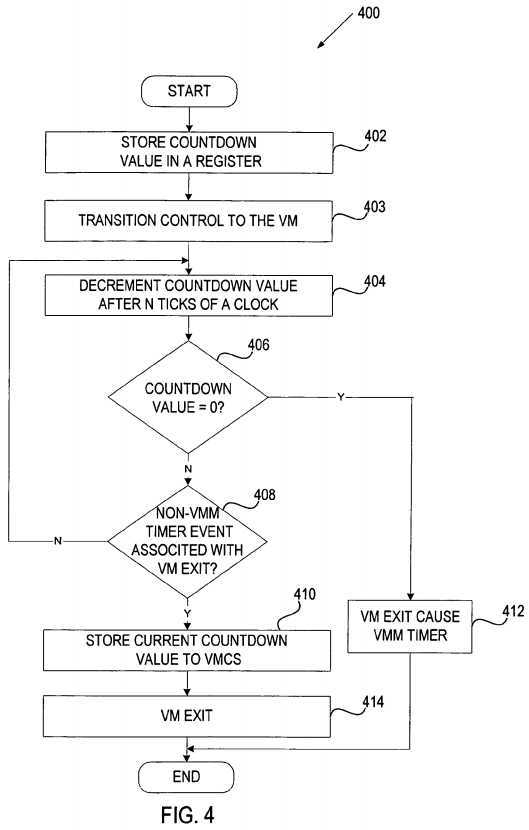
Initially, processing logic stores the offset value configured by the?VMM?(e.g., as stored in a preemption?timer?field in the VMCS) as a countdown value in a register (processing block?402). Next, processing logic transitions control to the VM (processing block?403). After transitioning control to the VM, processing logic begins decrementing the countdown value at the rate proportional to the increments of the clock (e.g., every N ticks of the clock) (processing block?404). After each decrement, processing logic checks whether the countdown value has reached 0 (processing box?406). Note that the decrementing of the countdown value may result in the value becoming negative. In this case, in an embodiment, the value is not allowed to be made lower than 0 (i.e., the decrementing stops at 0). Alternatively, the value may be allowed to be made lower than 0, in which case the determination at processing block?406?would be made determined by the value reaching or crossing 0. If the countdown value has reached (has matched or crossed) 0, processing logic issues an internal event and generates a VM exit, indicating that the source of the VM exit is the?VMM?timer?(processing block?412). In one embodiment, once the determination in processing block?406?is positive, a signal is generated that is recognized (e.g., by microcode or a hardware component) at the end of the currently executing instruction. The recognition of this signal indicates that a VM exit due to the?VMM?timer?may be required. This requirement is then prioritized (e.g., by microcode) with other VM exit sources, and the appropriate VM exit to the?VMM?is generated as discussed above.
If the countdown value has not yet reached 0, processing logic checks for a non-VMM?timer?event associated with a VM exit (processing box?408). If such event occurs, processing logic stores the current countdown value to the VMCS (processing block?410) and generates a VM exit, indicating the source of this VM exit (processing block?414). Otherwise, processing logic returns to processing block?404.
In an embodiment, the storing of the countdown?timer?value in processing block?410?may be controlled by a store?VMM timer?control value stored in the VMCS. If the store?VMM?timer?control is set to an enabled value, then the value of the countdown?timer?is stored (e.g., to the VMCS) as part of VM exit processing. In an embodiment, if the store?VMM?timer control is not set to an enabled value, a value of 0 is stored to the offset value configured by the?VMM?(e.g., to a field in the VMCS). In another embodiment, if the store?VMM?timer?control is not set to an enabled value the offset value configured by the?VMM?is not modified.
FIG. 5?is a flow diagram of one embodiment of a process?500?for configuring a?timer?associated with a?VMM. The process may be performed by processing logic that may comprise hardware (e.g., circuitry, dedicated logic, programmable logic, microcode, etc.), software (such as that run on a general purpose computer system or a dedicated machine), or a combination of both. In one embodiment, process?500?is performed by a?timer?configuration module?126?of?FIG. 1.
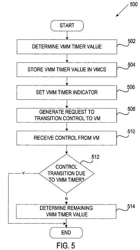
Referring to?FIG. 5, process?500?begins with processing logic determining a?VMM?timer?value (processing block?502) and storing it in the VMCS (processing block?504). In one embodiment, the?VMM?timer?value specifies the time at which control should be returned to the?VMM. Examples of calculating the?VMM?timer?value are provided below.
Next, processing logic sets a?VMM?timer?indicator to an enabling value (processing block?506) and issues a request to transition control to the VM (a VM entry request) (processing logic?508).
Subsequently, when a VM exit from the VM is generated, processing logic receives control back (processing block?510) and determines whether control was returned due to the?VMM?timer?(processing block?512). If so, processing logic may perform a desired operation and then generate a VM entry to the same VM or a different VM.
Prior to generating the VM entry, processing logic may need to update the VM?timer?indicator and/or the?VMM?timer?value (processing block?514). In one embodiment, the remaining time was saved to the VMCS prior to the VM exit (as discussed above with respect to?FIG. 4). In another embodiment, the remaining time is calculated by processing logic upon receiving control from the VM.
In an embodiment, the?VMM?timer?is used to determine a scheduling quantum for a VM. When a VM is scheduled to execute, it is assigned a quantum value by the?VMM. This value is initially used for the?VMM?timer?value. Upon transition to the VM, processing logic will utilize the countdown?VMM?timer?value as described with respect to?FIG. 4. Before control is transitioned to the?VMM, processing logic determines how much time was left in the time quantum allocated to the VM. In one embodiment, processing logic calculates the remaining time by reading the time value of the timing source prior to transitioning control to the VM and when receiving control from the VM. The difference of these two values indicates how long the VM was executing. This value is then subtracted from the time allocated to the VM. When the remaining time value reaches 0, the VMs scheduling quantum is consumed, and the?VMM?may then schedule a different VM to execute.
In one embodiment, the?VMM?timer?value is used to limit the maximum time that may be spent in the VM. An offset value (i.e., a time interval specifying how long the VM is allowed to execute) is added to the value of the timing source read by the VMM?at the time of calculation. This value is used as the?VMM?timer?value. Upon transition to the VM, processing logic will utilize this value as described with respect to?FIG. 3. This same value is used each time control is transitioned to the VM. In this embodiment, the?VMM?timer?acts as a watchdog?timer, limiting the longest execution time in the VM, in the absence of other VM exit sources. Note that in an embodiment, a countdown?timer?(as described with respect to?FIG. 4) may also be utilized to realize a watchdog?timer?mechanism.
Thus, a method and apparatus for providing support for a?timer?associated with a?VMM?have been described. It is to be understood that the above description is intended to be illustrative, and not restrictive. Many other embodiments will be apparent to those of skill in the art upon reading and understanding the above description. The scope of the invention should, therefore, be determined with reference to the appended claims, along with the full scope of equivalents to which such claims are entitled.
SRC=https://www.google.com.hk/patents/US7840962
标签:des style blog http color os io ar strong
原文地址:http://www.cnblogs.com/coryxie/p/3961963.html