标签:immediate issue middle ras center lin render soft imu

Depth precision is a pain in the ass that every graphics programmer has to struggle with sooner or later. Many articles and papers have been written on the topic, and a variety of different depth buffer formats and setups are found across different games, engines, and devices.
Because of the way it interacts with perspective projection, GPU hardware depth mapping is a little recondite and studying the equations may not make things immediately obvious. To get an intuition for how it works, it‘s helpful to draw some pictures.
This article has three main parts. In the first part, I try to provide some motivation for nonlinear depth mapping. Second, I present some diagrams to help understand how nonlinear depth mapping works in different situations, intuitively and visually. The third part is a discussion and reproduction of the main results of Tightening the Precision of Perspective Rendering by Paul Upchurch and Mathieu Desbrun (2012), concerning the effects of floating-point roundoff error on depth precision.
GPU hardware depth buffers don‘t typically store a linear representation of the distance an object lies in front of the camera, contrary to what one might na?vely expect when encountering this for the first time. Instead, the depth buffer stores a value proportional to the reciprocal of world-space depth. I want to briefly motivate this convention.
In this article, I‘ll use d to represent the value stored in the depth buffer (in [0, 1]), and z to represent world-space depth, i.e. distance along the view axis, in world units such as meters. In general, the relationship between them is of the form

On the face of it, you can imagine taking d to be any function of z you like. So why this particular choice? There are two main reasons.
First, 1/z fits naturally into the framework of perspective projections. This is the most general class of transformation that is guaranteed to preserve straight lines—which makes it convenient for hardware rasterization, since straight edges of triangles stay straight in screen space. We can generate linear remappings of 1/z by taking advantage of the perspective divide that the hardware already performs:
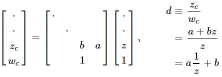
The second reason is that 1/z is linear in screen space, as noted by Emil Persson. So it‘s easy to interpolate d across a triangle while rasterizing, and things like hierarchical Z-buffers, early Z-culling, and depth buffer compression are all a lot easier to do.
Equations are hard; let‘s look at some pictures!
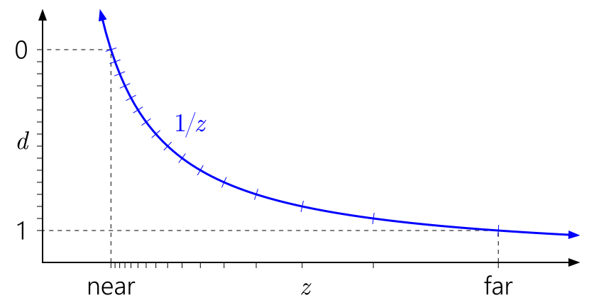
The way to read these graphs is left to right, then down to the bottom. Start with d, plotted on the left axis. Because d can be an arbitrary linear remapping of 1/z, we can place 0 and 1 wherever we wish on this axis. The tick marks indicate distinct depth buffer values. For illustrative purposes, I‘m simulating a 4-bit normalized integer depth buffer, so there are 16 evenly-spaced tick marks.
Trace the tick marks horizontally to where they hit the 1/z curve, then down to the bottom axis. That‘s where the distinct values fall in the world-space depth range.
The graph above shows the “standard”, vanilla depth mapping used in D3D and similar APIs. You can immediately see how the 1/z curve leads to bunching up values close to the near plane, and the values close to the far plane are quite spread out.
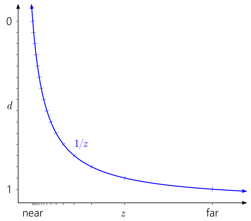
It‘s also easy to see why the near plane has such a profound effect on depth precision. Pulling in the near plane will make the d range skyrocket up toward the asymptote of the 1/z curve, leading to an even more lopsided distribution of values:
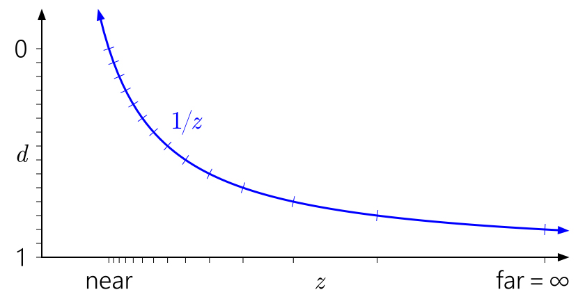
Similarly, it‘s easy to see in this context why pushing the far plane all the way out to infinity doesn‘t have that much effect. It just means extending the d range slightly down to 1/z=0:
What about floating-point depth? The following graph adds tick marks corresponding to a simulated float format with 3 exponent bits and 3 mantissa bits:
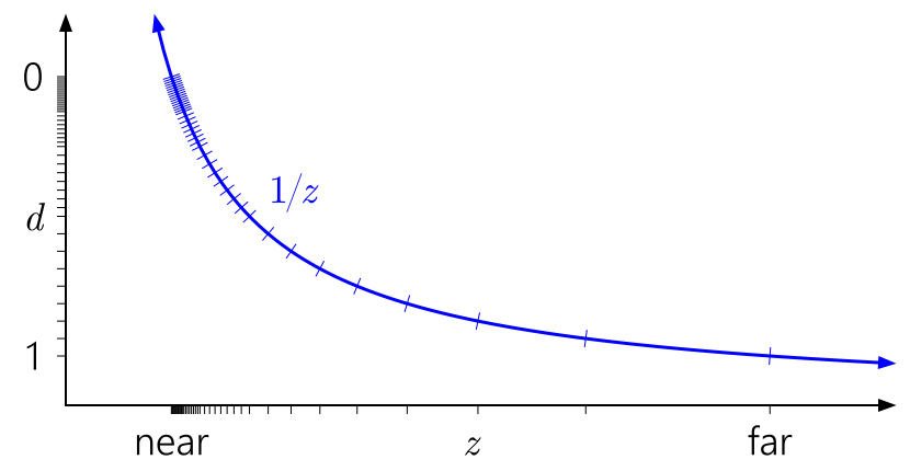
There are now 40 distinct values in [0, 1]—quite a bit more than the 16 values previously, but most of them are uselessly bunched up at the near plane where we didn‘t really need more precision.
A now-widely-known trick is to reverse the depth range, mapping the near plane to d=1 and the far plane to d=0:
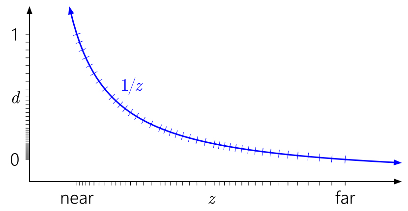
Much better! Now the quasi-logarithmic distribution of floating-point somewhat cancels the 1/z nonlinearity, giving us similar precision at the near plane to an integer depth buffer, and vastly improved precision everywhere else. The precision worsens only very slowly as you move farther out.
The reversed-Z trick has probably been independently reinvented several times, but goes at least as far back as a SIGGRAPH ’99 paper by Eugene Lapidous and Guofang Jiao (no open-access link available, unfortunately). It was more recently re-popularized in blog posts by Matt Pettineo and Brano Kemen, and by Emil Persson‘s Creating Vast Game Worlds SIGGRAPH 2012 talk.
All the previous diagrams assumed [0, 1] as the post-projection depth range, which is the D3D convention. What about OpenGL?
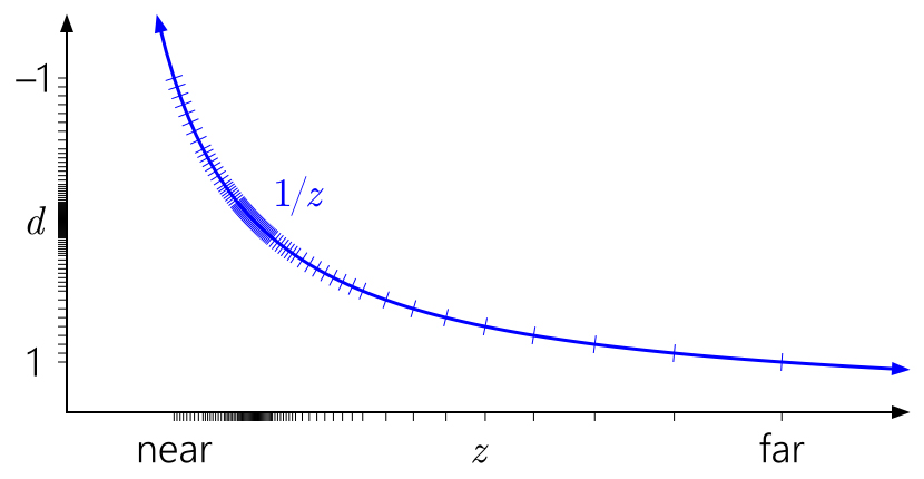
OpenGL by default assumes a [-1, 1] post-projection depth range. This doesn‘t make a difference for integer formats, but with floating-point, all the precision is stuck uselessly in the middle. (The value gets mapped into [0, 1] for storage in the depth buffer later, but that doesn‘t help, since the initial mapping to [-1, 1] has already destroyed all the precision in the far half of the range.) And by symmetry, the reversed-Z trick will not do anything here.
Fortunately, in desktop OpenGL you can fix this with the widely-supported ARB_clip_control extension (now also core in OpenGL 4.5 as glClipControl). Unfortunately, in GL ES you‘re out of luck.
The 1/z mapping and the choice of float versus integer depth buffer are a big part of the precision story, but not all of it. Even if you have enough depth precision to represent the scene you‘re trying to render, it‘s easy to end up with your precision controlled by error in the arithmetic of the vertex transformation process.
As mentioned earlier, Upchurch and Desbrun studied this and came up with two main recommendations to minimize roundoff error:
Upchurch and Desbrun came up with these recommendations through an analytical technique, based on treating roundoff errors as small random perturbations introduced at each arithmetic operation, and keeping track of them to first order through the transformation process. I decided to check the results using direct simulation.
My source code is here—Python 3.4 with numpy. It works by generating a sequence of random points, ordered by depth, spaced either linearly or logarithmically between the near and far planes. Then it passes the points through view and projection matrices and the perspective divide, using 32-bit float precision throughout, and optionally quantizes the final result to 24-bit integer. Finally, it runs through the sequence and counts how many times two adjacent points (which originally had distinct depths) have either become indistiguishable because they mapped to the same depth value, or have actually swapped order. In other words, it measures the rate at which depth comparison errors occur—which corresponds to issues like Z-fighting—under different scenarios.
Here are the results obtained for near = 0.1, far = 10K, with 10K linearly spaced depths. (I tried logarithmic depth spacing and other near/far ratios as well, and while the detailed numbers varied, the general trends in the results were the same.)
In the table, “indist” means indistinguishable (two nearby depths mapped to the same final depth buffer value), and “swap” means that two nearby depths swapped order.
| Precomposed view- projection matrix | Separate view and projection matrices | |||
|---|---|---|---|---|
| float32 | int24 | float32 | int24 | |
| Unaltered Z values (control test) |
0% indist 0% swap |
0% indist 0% swap |
0% indist 0% swap |
0% indist 0% swap |
| Standard projection | 45% indist 18% swap |
45% indist 18% swap |
77% indist 0% swap |
77% indist 0% swap |
| Infinite far plane | 45% indist 18% swap |
45% indist 18% swap |
76% indist 0% swap |
76% indist 0% swap |
| Reversed Z | 0% indist 0% swap |
76% indist 0% swap |
0% indist 0% swap |
76% indist 0% swap |
| Infinite + reversed-Z | 0% indist 0% swap |
76% indist 0% swap |
0% indist 0% swap |
76% indist 0% swap |
| GL-style standard | 56% indist 12% swap |
56% indist 12% swap |
77% indist 0% swap |
77% indist 0% swap |
| GL-style infinite | 59% indist 10% swap |
59% indist 10% swap |
77% indist 0% swap |
77% indist 0% swap |
Apologies for not graphing these, but there are too many dimensions to make it easy to graph! In any case, looking at the numbers, a few general results are clear.
The above points are practically irrelevant, though, because the real result that matters here is: the reversed-Z mapping is basically magic. Check it out:
I think the conclusion here is clear. In any perspective projection situation, just use a floating-point depth buffer with reversed-Z! And if you can‘t use a floating-point depth buffer, you should still use reversed-Z. It isn‘t a panacea for all precision woes, especially if you‘re building an open-world environment that contains extreme depth ranges. But it‘s a great start.
Nathan is a Graphics Programmer, currently working at NVIDIA on the DevTech software team. You can read more on his blog here.
标签:immediate issue middle ras center lin render soft imu
原文地址:http://www.cnblogs.com/hustztz/p/7591031.html