标签:call his 判断 指针 const ilo 不同 前端 type
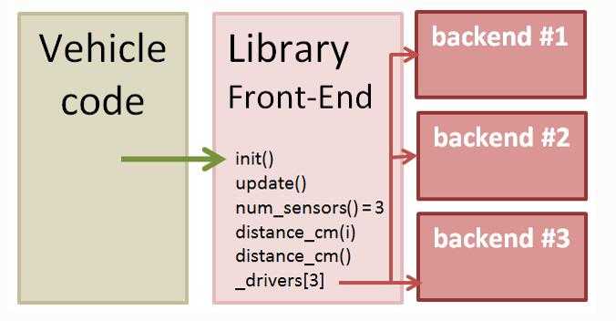
? Ardupilot设备驱动代码的层次结构采用 前端实现 和 后端实现 分割,前端库主要供机器代码层调用,后端库主要供前端调用。这里前端可以理解为应用层,后端理解为驱动层,前端调用后端代码,实际是驱动层提供接口供应用层使用。

? 前端调用后端代码之前,系统会通过自动检测设备或者通过用户配置的参数创建并且启动一个或者多个后端对象。用户自定义参数(_TYPE),例如RNGFND_TYPE。每个后端对象都会保存在前端创建的指针数组中( _drivers[])。
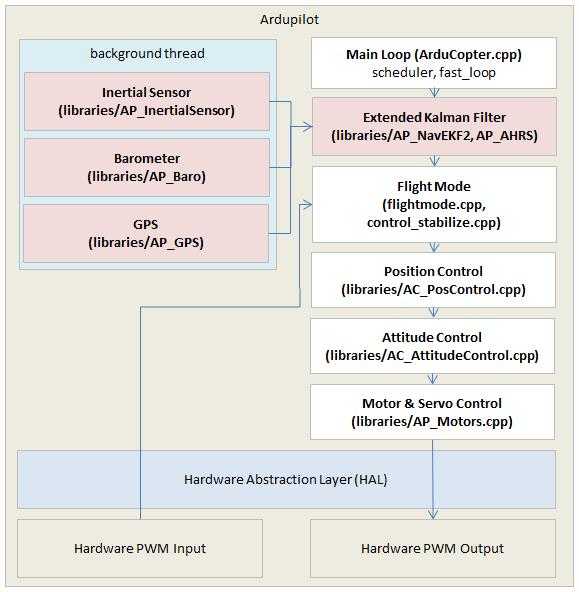
? 图中左边的后端设备驱动代码运行于后台线程中,主要实现从外部设备读取原始数据,转化为标准单位,并且将处理后的数据存储在缓冲区中。具体的飞行控制器代码通过调用前端代码获取最新的设备数据,并在主线程中周期处理运行(400HZ for copter)。例如从传感器的前端代码中读取加速度计、陀螺仪数据等。

其中,为了不阻碍主线程的运行,IIC和SPI通信在后台线程中运行。但主线程中可以调用USART接口函数,因为为底层的串行驱动程序本身在后台收集数据保存在一个缓冲区中。
sensors.cpp文件中包含有调用设备驱动前端代码,例如飞控控制以20HZ的频率调用read_rangefinder()函数而读取高度数据,而该函数内部则调用了rangefinder.update() 和rangefinder.set_estimated_terrain_height()前端代码来获取数据。摘取代码如下:
/*
  read the rangefinder and update height estimate
 */
void Plane::read_rangefinder(void)
{
 /* notify the rangefinder of our approximate altitude above ground to allow it     to power on*/
 /* during low-altitude flight when configured to power down during higher-altitude flight*/
    float height;
#if AP_TERRAIN_AVAILABLE
    if (terrain.status() == AP_Terrain::TerrainStatusOK && terrain.height_above_terrain(height, true)) {
        rangefinder.set_estimated_terrain_height(height);
    } else
#endif
    {
        /* use the best available alt estimate via baro above home*/
        if (flight_stage == AP_Vehicle::FixedWing::FLIGHT_LAND) {
            /* ensure the rangefinder is powered-on when land alt is higher than home altitude.
            This is done using the target alt which we know is below us and we are sinking to            it*/
            height = height_above_target();
        } else {
            /* otherwise just use the best available baro estimate above home.*/
            height = relative_altitude;
        }
        rangefinder.set_estimated_terrain_height(height); //设置地形估计高度
    }
?
    rangefinder.update();   //通过传感器更新高度数据
?
    if ((rangefinder.num_sensors() > 0) && should_log(MASK_LOG_SONAR)) {
        Log_Write_Sonar();
    }
?
    rangefinder_height_update();
}
以下代码为rangefinder.update()函数内部实现
/*
   update the state of the sensor by usart
*/
void AP_RangeFinder_LightWareSerial::update(void)
{
//获取缓冲区中获取的原始数据,并且将处理后的数据保存至distance_cm中,数据为true,否则为false
    if (get_reading(state.distance_cm)) {
        // update range_valid state based on distance measured
        last_reading_ms = AP_HAL::millis(); //获取当前系统运行时间
        update_status();    /*判断distance_cm数据情况,高于最大测量范围或者小于最小测量范围或者数据正常*/
    } else if (AP_HAL::millis() - last_reading_ms > 200) { /* 超过200ms缓冲没有数据 */
        set_status(RangeFinder::RangeFinder_NoData);
    }
}
此处以获取LightWare数据为例,首先需通过serial_manager类和用户设置的参数获取串口设备对象实例。代码如下:
/*
   The constructor also initialises the rangefinder. Note that this
   constructor is not called until detect() returns true, so we
   already know that we should setup the rangefinder
*/
AP_RangeFinder_LightWareSerial::AP_RangeFinder_LightWareSerial(RangeFinder::RangeFinder_State &_state, AP_SerialManager &serial_manager) : AP_RangeFinder_Backend(_state)
{
    uart = serial_manager.find_serial(AP_SerialManager::SerialProtocol_Lidar, 0);
    if (uart != nullptr) {
 uart->begin(serial_manager.find_baudrate(AP_SerialManager::SerialProtocol_Lidar, 0));
    }
}
前端代码在读取串口数据之前,需每次调用update()方法获取串口接受缓冲区中的数据,update方法中则调用的get_reading()方法将数据读取的内存中进行数据处理。其中关于update的代码可见之前的rangefinder.update()代码的实现,另外get_reading()代码如下:
// read - return last value measured by sensor
bool AP_RangeFinder_LightWareSerial::get_reading(uint16_t &reading_cm)
{
    if (uart == nullptr) {
        return false;
    }
?
    // read any available lines from the lidar
    float sum = 0;
    uint16_t count = 0;
    int16_t nbytes = uart->available(); //检测串口接收缓冲区中的数据个数
    while (nbytes-- > 0) { //将缓冲区的数据读出,可能会读到多组数据
        char c = uart->read();  //获取一个字符
        if (c == ‘\r‘) {        //一组数据以‘\r‘为结尾
            linebuf[linebuf_len] = 0;
            sum += (float)atof(linebuf); //将浮点字符串转换成字符串
            count++;
            linebuf_len = 0;
        } else if (isdigit(c) || c == ‘.‘) { //判断数据是否有效
            linebuf[linebuf_len++] = c;
            if (linebuf_len == sizeof(linebuf)) {
                // too long, discard the line
                linebuf_len = 0;
            }
        }
    }
?
    // we need to write a byte to prompt another reading
    uart->write(‘d‘);
?
    if (count == 0) {
        return false; //无数据返回false
    }
    reading_cm = 100 * sum / count;  //单位换算成cm,并且求多组数据的平均值
    return true; //有数据返回true
}
因系统中每个串口都有自己接收缓冲区,所以主线程中可以直接调用get_reading()方法,而不影响其性能。而IIC和SPI通信则需要通过另外的机制来获取数据。
前端代码通过指定IIC设备的地址而对IIC实例对象进行初始化,初始化代码位于RangeFinder.cpp文件中的RangeFinder::detect_instance(uint8_t instance)函数中:
case RangeFinder_TYPE_LWI2C:
        if (state[instance].address) {
#ifdef HAL_RANGEFINDER_LIGHTWARE_I2C_BUS
        _add_backend(AP_RangeFinder_LightWareI2C::detect(state[instance],
        hal.i2c_mgr->get_device(HAL_RANGEFINDER_LIGHTWARE_I2C_BUS, state[instance].address)));
#else
 if (!_add_backend(AP_RangeFinder_LightWareI2C::detect(state[instance],
      hal.i2c_mgr->get_device(1, state[instance].address)))) {
       _add_backend(AP_RangeFinder_LightWareI2C::detect(state[instance],
       hal.i2c_mgr->get_device(0, state[instance].address)));
 }
#endif
  }
    break;
其中代码
hal.i2c_mgr->get_device(HAL_RANGEFINDER_LIGHTWARE_I2C_BUS, state[instance].address)
通过指定IIC地址在总线上得到对应设备。指定设备之后,则可以通过调用相应的后端代码来初始化该设备与读取数据。代码如下:
void AP_RangeFinder_LightWareI2C::init()
{
    // call timer() at 20Hz 以20HZ的频率执行定时器回调函数
    _dev->register_periodic_callback(50000,
                                     FUNCTOR_BIND_MEMBER(&AP_RangeFinder_LightWareI2C::timer, void));
}
?
// read - return last value measured by sensor
bool AP_RangeFinder_LightWareI2C::get_reading(uint16_t &reading_cm)
{
    be16_t val;
?
    if (state.address == 0) {
        return false;
    }
?
    // read the high and low byte distance registers
    bool ret = _dev->read((uint8_t *) &val, sizeof(val));
    if (ret) {
        // combine results into distance
        reading_cm = be16toh(val);
    }
?
    return ret;
}
而定时回调函数中则调用了get_reading()方法获取IIC设备的数据。
以MPU9250 IMU后端代码介绍SPI总线后端代码的编写。获取SPI设备对象的初始化代码类似于IIC,代码位于AP_InertialSensor.cpp文件AP_InertialSensor::detect_backends(void)函数中。
_add_backend(AP_InertialSensor_Invensense::probe(*this, hal.spi->get_device(HAL_INS_MPU9250_NAME))); //获取SPI设备
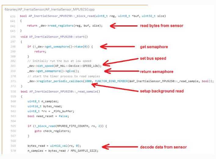
此外,在后台线程中start()方法会自动调用对SPI总线上对应设备(此处为MPU9250)进行初始化和配置。程序中使用信号量区别SPI总线上的不同设备。

其中,_read_sample()方法被注册以1000HZ的频率被调用。__block_read()方法则主要从传感器寄存器中获取数据供上层代码处理。
如果添加新的设备驱动程序代码,则在代码中绝对不能有任何的等待或者线程休眠代码,因为这样会影响其他线程所使用的总线。
如果想将新的驱动代码加入的工程中,则必须在make.inc和wscript文件中编写相应的工程代码,这两个文件位于对应的飞行器代码目录下(ArduPlane、ArduCopter...)。这样新编写的驱动才会参与工程代码的编译,最后一同生成可执行的二进制文件。后续可将该文件烧写至飞控处理器中运行。
标签:call his 判断 指针 const ilo 不同 前端 type
原文地址:http://www.cnblogs.com/BlogsOfLei/p/7745636.html