标签:des style blog class code tar
1. 什么是射频识别 (RFID) 技术?
射频识别 (RFID) 技术可使用无线广播通信对对象或人进行唯一识别,是当今发展速度最快的自动数据采集 (ADC) 技术之一。
RFID 开创了一种可自动收集产品、位置、时间或事务处理等信息的新方法,既简单快捷,又不会出现人为错误。
它提供了一种无需视线触及的非接触式数据链路,例如硬纸板盒内的物品,或者有关更严苛或更恶劣环境中的信息,这些环境将严重制约其它自动 ID 技术(例如条形码等)。
此外,RFID 不仅是一个 ID 代码,其还可用作数据载体,将信息即时写入和更新到相关标签上。
2. 完整的 RFID 系统包含哪些组件?
RFID 系统包含众多组件,如标签、手持式或固定式读取器、天线以及系统软件等。
读取器由发送器、接收器、控制模块和通信功能构成。从无线电广播的角度讲,读取器有时也称为收发器,因为它可以链接至控制 PC。
应答器或标签可用于进行对象识别,能编入与对象相关的独特信息。
读取器应配套提供一根用于收发射频信号的天线。每个读取器都附带与 PC 兼容的软件,以便用户能够读取标签并对其进行编程。
要求具备串行通信端口 RS232 或 RS422/485。
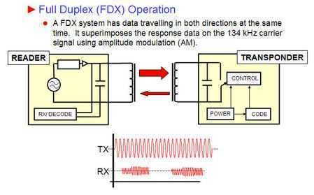
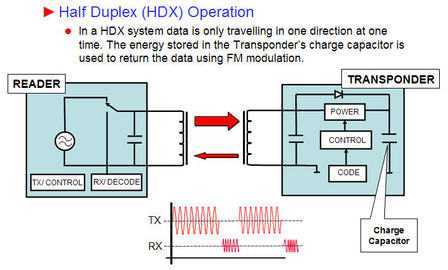
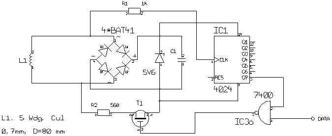
TI’s fundamental LF design uses half-duplex (HDX) RF communication.
In an HDX system, data communicated between the RF transponder, or tag, and the reader is only traveling in one direction at a time.
The RF reader sends a signal to the tag to activate it, and subsequently shuts down to “listen” to the tag’s response.
TI’s transponders incorporate a charge capacitor, which acts like a battery.
The energy stored in the tag’s charge capacitor is used to return data to the reader via a FM signal versus an AM signal (full-duplex (FDX) systems).
In other words, HDX systems use the stored energy to respond in “radio silence” after the carrier (reader) signal is turned off.
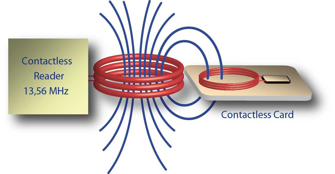
RFID chips use radio signals to transmit data over short distances.
They are used typically for security, tracking, and identification purposes.
RFID chips can be paired with other circuitry to create tags or readers that also use radio frequency identification (RFID) technology.
RFID chips wirelessly transmit their unique serial-number identifiers, even when embedded in objects such as clothing or currency.
When an RFID reader broadcasts a request for this information, the RFID tag that contains the corresponding ID code responds with a transmission.
Some of these RFID devices do not have batteries, and are instead powered by the radio signals themselves.
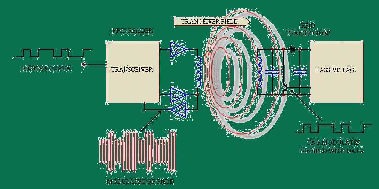
This diagram shows the role of an RFID chip in a transponder.
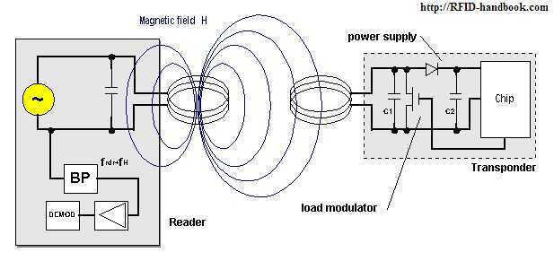
Picture: sample circuit of the power supply and load modulator in a transponder
Picture above:
If the additional load resistor in the transponder is switched on and off at a very high elementary frequency fH,
then two spectral lines are created at a distance of ±fH around the transmission frequency of the reader,
and these can be easily detected (however fH must be less than fREADER).
In the terminology of radio technology the new elementary frequency is called a subcarrier.
Data transfer is by the ASK, FSK or PSK modulation of the subcarrier in time with the data flow.
This represents an amplitude modulation of the subcarrier.
We know from the field of RADAR technology that electromagnetic waves are reflected by objects with dimensions greater than around half the wavelength of the wave.
The efficiency with which an object reflects electromagnetic waves is described by its reflection cross-section.
Objects that are in resonance with the wave front that hits them, as is the case for antenna at the appropriate frequency for example, have a particularly large reflection cross-section.
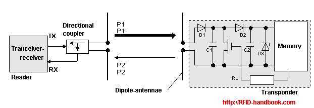
Picture: Operation principle of a backscatter transponder
Power P1 is emitted from the reader‘s antenna, a small proportion of which (free space attenuation) reaches the transponder‘s antenna.
The power P1‘ is supplied to the antenna connections as HF voltage and after rectification by the diodes D1 and D2 this can be used as turn on voltage for the deactivation or activation of the power saving "power-down" mode.
The diodes used here are low barrier Schottky diodes, which have a particularly low threshold voltage.
The voltage obtained may also be sufficient to serve as a power supply for short ranges.
A proportion of the incoming power P1‘ is reflected by the antenna and returned as power P2.
The reflection characteristics (= reflection cross-section) of the antenna can be influenced by altering the load connected to the antenna.
In order to transmit data from the transponder to the reader, a load resistor RL connected in parallel with the antenna is switched on and off in time with the data stream to be transmitted.
The amplitude of the power P2 reflected from the transponder can thus be modulated (à modulated backscatter).
The power P2 reflected from the transponder is radiated into free space.
A small proportion of this (free space attenuation) is picked up by the reader‘s antenna.
The reflected signal therefore travels into the antenna connection of the reader in the "backwards direction" and can be decoupled using a directional coupler and transferred to the receiver input of a reader.
The "forward" signal of the transmitter, which is stronger by powers of ten, is to a large degree suppressed by the directional coupler.
The ratio of power transmitted by the reader and power returning from the transponder (P1 / P2) can be estimated using the radar equation
(for a more detailed explanation, please refer to the chapter 4 "Physical Principles" of the RFID-handbook).
The GlobalSpec SpecSearch database categorizes RFID chips according to the type of device (passive, active, or semi-passive) in which the chips are used.
Suppliers may also designate their products as encrypted or short-range.
RFID chips may be equipped with a serial, wireless, TTL, or
I2C interface.
Frequency, memory, read rate, detection range and operation
temperature are the key performance specifications to consider.
When
specifying the frequency, industrial buyers should note that products use low,
high, ultra-high and microwave frequencies.
Each has advantages and
disadvantages, depending upon the user‘s application.
Like other types of radio frequency identification (RFID)
products, some chips can operate without physical contact between the tag and
the reader.
Portability, encryption, and continuous reporting are also
important features to consider, depending upon the application.
http://www.apdanglia.org.uk/rfidbasics.html
How do RFIDs work.
标签:des style blog class code tar
原文地址:http://www.cnblogs.com/shangdawei/p/3721763.html