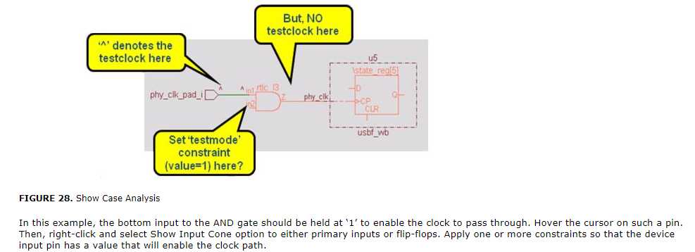
View the Incremental Schematic of the violation message. The Schematic Viewer window shows the flip-flop on which the clock does not reach. Ensure that the complete display mode is set.
Since the violation message provides information on identification of potential clocks, overlay (auxiliary violation mode) the Info_testmode rule and Info_testclock under shift_mode.
Double-click the Incremental Schematic to probe the fan-in code of the failing clock source. Identify the path on the basis of the signal name. The probed signal is annotated with the shift_mode clock value, which is ^ for rising-edge and V for falling-edge. Absence of any value implies that no test_clock has reached this point.

Async_07
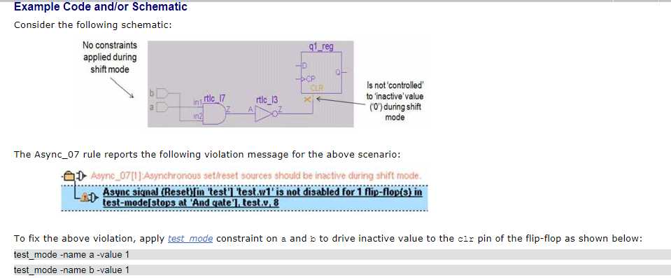
在shift mode, flip-flop的异步set/reset source 是active的。
Fix
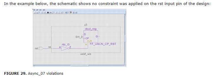
View the Incremental Schematic of the violation message. The Schematic Viewer window shows the flip-flop on which the asynchronous control is not deactivated. Overlay (Auxiliary violation mode) the
Info_testmode rule in shift mode. This helps in identifying the blocked values.Double-click the schematic and start probing the fan-in cone of the failing asynchronous source. Identify the path on the basis of the signal name. The probed signal is annotated with a shift mode value, which is either 0 or 1. Absence of any value implies that neither 0 nor 1 has reached to this point. Presence of X as a shift mode value may imply potential contention.
You can also double-click on the violation message to view the spreadsheet that lists the details of the flip-flops for which the async signal is not disabled in the test mode.
To fix the violation, either fix the test mode or the async signal
例1.

例2.


