标签:des style blog http color io os ar strong
Protecting computer systems from attacks that attempt to change USB topology and for ensuring that the system‘s information regarding USB topology is accurate is disclosed. A software model is defined that, together with secure USB hardware, provides an ability to define policies using which USB traffic can be properly monitored and controlled. The implemented policy provides control over USB commands through a combination of software evaluation and hardware programming. Legitimate commands are evaluated and "allowed" to be sent to a USB device by a host controller. Illegitimate commands are evaluated and blocked. Additionally, the USB topology is audited to verify that the system‘s topology map matches the actual USB topology.
FIELD OF THE INVENTION
The invention generally relates to the field of the universal serial bus (USB) and specifically to the security of data associated with the USB.
BACKGROUND OF THE INVENTION
The manner in which USB peripherals are attached to a USB Host Controller and the manner in which USB drivers communicate with their corresponding devices make it difficult to prevent malicious software from mounting different classes of attacks that attempt to modify the USB topology. Such attacks may take various forms such as, for example, substitution attacks and snooping attacks.
A substitution attack involves substituting an illegitimate USB device for a legitimate device without the system recognizing that a substitution occurred. Each USB device is attached to a port on either a root hub or an external hub. A hub driver controls the state of its hub ports by sending certain USB commands over the hub‘s default pipe (endpoint 0). A malicious driver may hide a programmable USB device attached to one of the hub ports by disabling the port to which the device is connected. The driver then may be able to disable a port of a real keyboard that is attached to the same hub and enable the port of the programmable device. In addition, the malicious driver may set the USB address of its programmable device to the address that was assigned to the keyboard it disabled. The end result is that the real keyboard is spoofed by a programmable device, and the driver for the keyboard is not aware that it is talking to a different device. In sum, the system believes that input data is generated by the keyboard when the data is generated programmatically by an adversary.
Another type of attack, the snooping attack, attempts to modify USB topology by taking advantage of a process in which a device driver reads data from its device by sending it an appropriate USB command. Some data sent by a device ideally should not be read by any entity besides the applicable device driver. An example of such case is when the device has to exchange an encryption key with the driver so that the driver can use the key for decrypting data that the device is going to generate later. An adversary may obtain sensitive data by either sending an appropriate command to the device or by mounting an attack in which the adversary grabs data en route to the requesting device driver. Additionally, it is recognized that a software solution may make it more difficult for an attacker to obtain sensitive information, but software alone likely cannot provide full protection against such attacks.
Additionally, in a computer system with a USB Host Controller and USB peripherals connected to it, it is desirable for software to be able to obtain information regarding USB topology. It is currently possible for legitimate system software to obtain such information. Malicious software, however, may tamper with topology information such that legitimate software may not be able to verify that topology information it receives appropriately reflects actual USB topology. For example, an adversary may program a USB device so that it looks to the system like a different device, such as a keyboard. Because the system may need to secure certain USB input devices in order to establish a trusted path with a user, mounting this attack leads the system to "trust" a keyboard device even though it is not a really a keyboard. A malicious driver mounts the attack by sending a USB command that configures a physical programmable device. The host controller driver queries the device for its USB descriptors, and the device returns descriptors indicating that the device is a keyboard. Thus, the system loads a keyboard driver for controlling that device.
This driver then waits for input data to be generated by the device. At that point, the malicious driver can trigger the device to generate one or more keystrokes by sending an appropriate USB command to the device. When these keystrokes are generated, the keyboard driver sends the corresponding keyboard events to the operating system. The end result is that the malicious driver can inject input events into the system. This also provides the malicious driver with the ability to have the device "playback" a certain keystroke sequence at a specific time, which may create general problems and may even enable the driver to inject input into a trusted input path as if the input was generated by a trusted device.
There is a need, therefore, for systems and methods to prevent attacks on USB systems that attempt to change USB topology and to audit USB topology to ensure that the information that the system maintains regarding the attached USB devices appropriately reflects the actual USB topology. The systems and methods ideally should not be based solely in software.
SUMMARY OF THE INVENTION
The invention provides systems and methods for protecting computer systems from attacks that attempt to change USB topology and for ensuring that the system‘s information regarding USB topology is accurate. The invention includes defining a software model that, together with secure USB hardware, provides an ability to define policies using which USB traffic can be properly monitored and controlled. The implemented policy provides control over USB commands through a combination of software evaluation and hardware programming. Legitimate commands are evaluated and "allowed" to be sent to a USB device through the host controller. Illegitimate commands are evaluated and blocked.
The invention may be implemented to control USB topology changes. Because most topology changes involve a USB setup command sent to a relevant USB hub, trusted software may monitor such commands so that the status of USB devices connected downstream from the hub is accurate. According to the invention, data associated with a USB device, such as a setup command, is received by trusted software, and a determination is made regarding whether the data is allowed to be sent to the targeted USB device. If the data is allowed, then an instruction is sent to a host controller driver to send the data. Additionally, the trusted software may program a security extension residing on a host controller chipset to allow the data through to the USB topology and device. If the data is not allowed, then the trusted software may program the security extension to block the data from going through.
The invention includes auditing the USB topology to verify that the system‘s topology map matches the actual USB topology. The invention defines a model in which software and hardware are used together in order to perform the USB topology audit in a trustworthy fashion. Auditing the USB topology is valuable when certain USB devices need to be differentiated from other devices. For example, input devices may be differentiated from other USB devices because a user may generate secure input. The differentiation may provide for the establishment of a trusted input path between the user and the system application receiving the user input. The USB topology audit provides an ability to detect input devices residing in the topology in a trustworthy fashion and protects against security attacks to the system through the USB topology.
The USB audit includes receiving a USB topology map from a USB host controller driver. The map, generated by untrusted software, is verified by trusted software through a series of commands sent to the USB topology through the host controller chipset. The devices provide identifying information that is compared against the map. The identifying information received from the devices is diverted to a secure buffer in the security extension hardware and therefore trusted software is guaranteed to receive device data that hasn‘t been tampered with by malicious software. Before sending the aforementioned commands to the devices, the trusted software resumes all ports of the hubs in the topology in order to make sure that malicious software has not hidden a device by suspending the hub port to which the device is connected. Once the identifying information is received and scrutinized, trusted software compares the number of active hub ports with the number of devices and makes sure they are equal and that there are no hidden devices in the topology. The audit also includes identifying and securing input devices such that information generated by the input devices is diverted through a secure buffer in the security extension for evaluation within a trusted execution environment in the system.
BRIEF DESCRIPTION OF THE DRAWINGS
The foregoing summary and the following detailed description of the invention are better understood when read in conjunction with the appended drawings. Embodiments of the invention are shown in the drawings, however, it is understood that the invention is not limited to the specific methods and instrumentalities depicted therein. In the drawings:
FIG. 1 is a block diagram showing an example computing environment in which aspects of the invention may be implemented;
FIG. 2 is block diagram of an example system for using a USB host controller security extension for controlling changes in and auditing USB topology according to the invention;
FIG. 3 is a flow diagram of an example method for controlling delivery of USB commands to USB devices according to the invention;
FIG. 4 is a flow diagram of an example method for controlling delivery of USB commands regarding cryptographic keys according to the invention;
FIGS. 5A-5B depict a flow diagram of an example method for auditing a USB topology according to the invention; and
FIG. 6 is a block diagram of an example system for auditing a USB topology according to the invention.
DETAILED DESCRIPTION OF ILLUSTRATIVE EMBODIMENTS
FIG. 1 and the following discussion are intended to provide a brief general description of a suitable computing environment?100?in which an example embodiment of the invention may be implemented. As used herein, the terms "computing system," "computer system," and "computer" refer to any machine, system or device that comprises a processor capable of executing or otherwise processing program code and/or data. Examples of computing systems include, without any intended limitation, personal computers (PCs), minicomputers, mainframe computers, thin clients, network PCs, servers, workstations, laptop computers, hand-held computers, programmable consumer electronics, multimedia consoles, game consoles, satellite receivers, set-top boxes, automated teller machines, arcade games, mobile telephones, personal digital assistants (PDAs) and any other processor-based system or machine. The term "data" refers to any information of any form, including commands, transfers, or requests. The terms "program code" and "code" refer to any set of instructions that are executed or otherwise processed by a processor. The term "untrusted program code" or "untrusted code" refers to any set of instructions that are executed or otherwise processed by a processor outside of a trusted execution environment. The term "device driver" refers to any program code that at least in part controls a component of a computer system, such as a USB device, or facilitates communication of data between a component and other devices or program code of a computer system. The term "trusted execution environment" refers to an environment comprising trusted program code that is isolated from other code located outside of the trusted execution environment and to which security policies are applied to provide secure execution of the program code.
The term "universal serial bus" or "USB" refers to a cable bus that supports data exchange between a host computer and a wide range of accessible peripheral devices or functions. "USB device," "USB function," "USB peripheral" or "peripheral" refers to devices that may be attached or that are attached to a USB. USB devices, functions, or peripherals share USB bandwidth through a host-scheduled, token-based protocol. The USB allows peripherals to be attached, configured, used, and detached while the host and other peripherals are in operation.
While a general purpose computer is described below, this is merely one example. The present invention also may be operable on a thin client having network server interoperability and interaction. Thus, an example embodiment of the invention may be implemented in an environment of networked hosted services in which very little or minimal client resources are implicated, e.g., a networked environment in which the client device serves merely as a browser or interface to the World Wide Web.
Although not required, the invention can be implemented via an application programming interface (API), for use by a developer or tester, and/or included within the network browsing software which will be described in the general context of computer-executable instructions, such as program modules, being executed by one or more computers (e.g., client workstations, servers, or other devices). Generally, program modules include routines, programs, objects, components, data structures and the like that perform particular tasks or implement particular abstract data types. Typically, the functionality of the program modules may be combined or distributed as desired in various embodiments. An embodiment of the invention may also be practiced in distributed computing environments where tasks are performed by remote processing devices that are linked through a communications network or other data transmission medium. In a distributed computing environment, program modules may be located in both local and remote computer storage media including memory storage devices.
FIG. 1 illustrates an example of a suitable computing system environment?100?in which the invention may be implemented, although as made clear above, the computing system environment?100?is only one example of a suitable computing environment and is not intended to suggest any limitation as to the scope of use or functionality of the invention. Nor should the computing environment?100?be interpreted as having any dependency or requirement relating to any one or combination of components illustrated in the exemplary operating environment?100.
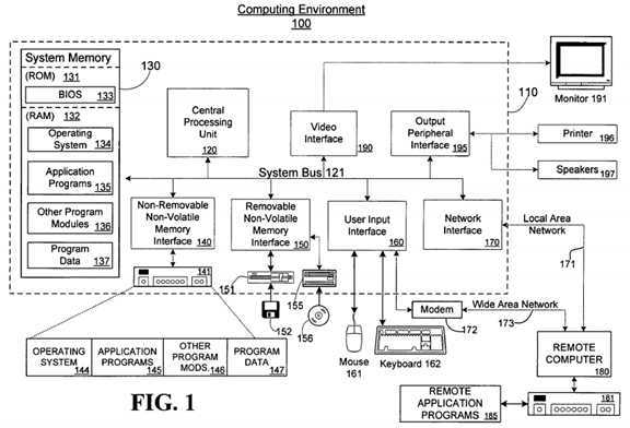
With reference to FIG. 1, an example system for implementing the invention includes a general purpose computing device in the form of a computer110. Components of computer?110?may include, but are not limited to, a central processing unit?120, a system memory?130, and a system bus?121?that couples various system components including the system memory to the processing unit?120. The system bus?121?may be any of several types of bus structures including a memory bus or memory controller, a peripheral bus, and a local bus using any of a variety of bus architectures. By way of example, and not limitation, such architectures include Industry Standard Architecture (ISA) bus, Micro Channel Architecture (MCA) bus, Enhanced ISA (EISA) bus, Video Electronics Standards Association (VESA) local bus, and Peripheral Component Interconnect (PCI) bus (also known as Mezzanine bus).
Computer?110?typically includes a variety of computer readable media. Computer readable media can be any available media that can be accessed by computer?110?and includes both volatile and nonvolatile, removable and non-removable media. By way of example, and not limitation, computer readable media may comprise computer storage media and communication media. Computer storage media includes both volatile and nonvolatile, removable and non-removable media implemented in any method or technology for storage of information such as computer readable instructions, data structures, program modules or other data. Computer storage media includes, but is not limited to, random access memory (RAM), read-only memory (ROM), Electrically-Erasable Programmable Read-Only Memory (EEPROM), flash memory or other memory technology, compact disc read-only memory (CDROM), digital versatile disks (DVD) or other optical disk storage, magnetic cassettes, magnetic tape, magnetic disk storage or other magnetic storage devices, or any other medium which can be used to store the desired information and which can be accessed by computer?110. Communication media typically embodies computer readable instructions, data structures, program modules or other data in a modulated data signal such as a carrier wave or other transport mechanism and includes any information delivery media. The term "modulated data signal" means a signal that has one or more of its characteristics set or changed in such a manner as to encode information in the signal. By way of example, and not limitation, communication media includes wired media such as a wired network or direct-wired connection, and wireless media such as acoustic, radio frequency (RF), infrared, and other wireless media. Combinations of any of the above are also included within the scope of computer readable media.
The system memory?130?includes computer storage media in the form of volatile and/or nonvolatile memory such as ROM?131?and RAM?132. A basic input/output system?133?(BIOS) containing the basic routines that help to transfer information between elements within computer?110, such as during start-up, is typically stored in ROM?131. RAM?132?typically contains data and/or program modules that are immediately accessible to and/or presently being operated on by processing unit?120. By way of example, and not limitation, FIG. 1 illustrates operating system?134, application programs?135, other program modules?136, and program data?137. RAM?132?may contain other data and/or program modules.
The computer?110?may also include other removable/non-removable, volatile/nonvolatile computer storage media. By way of example only, FIG. 1 illustrates a hard disk drive?141?that reads from or writes to non-removable, nonvolatile magnetic media, a magnetic disk drive?151?that reads from or writes to a removable, nonvolatile magnetic disk?152, and an optical disk drive?155?that reads from or writes to a removable, nonvolatile optical disk156, such as a CD ROM or other optical media. Other removable/non-removable, volatile/nonvolatile computer storage media that can be used in the example operating environment include, but are not limited to, magnetic tape cassettes, flash memory cards, digital versatile disks, digital video tape, solid state RAM, solid state ROM, and the like. The hard disk drive?141?is typically connected to the system bus?121?through a non-removable memory interface such as interface?140, and magnetic disk drive?151?and optical disk drive?155?are typically connected to the system bus?121?by a removable memory interface, such as interface?150.
The drives and their associated computer storage media discussed above and illustrated in FIG. 1 provide storage of computer readable instructions, data structures, program modules and other data for the computer?110. In FIG. 1, for example, hard disk drive?141?is illustrated as storing operating system?144, application programs?145, other program modules?146, and program data?147. Note that these components can either be the same as or different from operating system?134, application programs?135, other program modules?136, and program data?137. Operating system?144, application programs?145, other program modules?146, and program data?147?are given different numbers here to illustrate that, at a minimum, they are different copies. A user may enter commands and information into the computer?110?through input devices such as a keyboard?162?and pointing device?161, commonly referred to as a mouse, trackball or touch pad. Other input devices (not shown) may include a microphone, joystick, game pad, satellite dish, scanner, or the like. These and other input devices are often connected to the processing unit?120?through a user input interface?160?that is coupled to the system bus?121, but may be connected by other interface and bus structures, such as a parallel port, game port or a universal serial bus (USB).
A monitor?191?or other type of display device is also connected to the system bus?121?via an interface, such as a video interface?190. In addition to monitor?191, computers may also include other peripheral output devices such as speakers?197?and printer?196, which may be connected through an output peripheral interface?195.
The computer?110?may operate in a networked environment using logical connections to one or more remote computers, such as a remote computer180. The remote computer?180?may be a personal computer, a server, a router, a network PC, a peer device or other common network node, and typically includes many or all of the elements described above relative to the computer?110, although only a memory storage device?181?has been illustrated in FIG. 1. The logical connections depicted in FIG. 1 include a local area network (LAN)?171?and a wide area network (WAN)?173, but may also include other networks. Such networking environments are commonplace in offices, enterprise-wide computer networks, intranets and the Internet.
When used in a LAN networking environment, the computer?110?is connected to the LAN?171?through a network interface or adapter?170. When used in a WAN networking environment, the computer?110?typically includes a modem?172?or other means for establishing communications over the WAN?173, such as the Internet. The modem?172, which may be internal or external, may be connected to the system bus?121?via the user input interface?160, or other appropriate mechanism. In a networked environment, program modules depicted relative to the computer?110, or portions thereof, may be stored in the remote memory storage device. By way of example, and not limitation, FIG. 1 illustrates remote application programs?185?as residing on memory device?181. It will be appreciated that the network connections shown are exemplary and other means of establishing a communications link between the computers may be used.
A computer?110?or other client device can be deployed as part of a computer network. In this regard, the present invention pertains to any computer system having any number of memory or storage units, and any number of applications and processes occurring across any number of storage units or volumes. An embodiment of the present invention may apply to an environment with server computers and client computers deployed in a network environment, having remote or local storage. The present invention may also apply to a standalone computing device, having programming language functionality, interpretation and execution capabilities.
Example Embodiments
FIG. 2 is block diagram of an example system?200?for using a USB host controller security extension for controlling changes in and auditing USB topology, according to the invention. The system?200?may be the computer?110?of FIG. 1 and may generally be divided into USB related hardware?250, a trusted execution environment?220, and an area outside of the trusted execution environment?211.
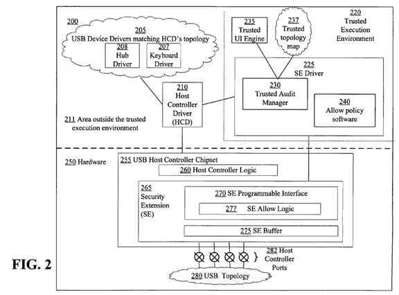
The hardware?250?includes a USB host controller chipset?255?with a hardware security extension (SE)?265, and a USB topology?280. The USB host controller chipset?255?is a hardware component to which USB devices are or may be attached. The USB host controller chipset?255?includes several ports?282?that are referred to as root ports or root hub ports. USB related data sent from, for example, a USB device driver to an associated USB device in the USB topology?280?is delivered by the USB host controller chipset?255. Likewise data sent from a USB device in the USB topology?280?to its device driver is delivered by or via the USB host controller chipset?255.
The USB topology?280?includes USB devices that are connected downstream from the USB host controller chipset?255. The USB topology?280?may also be referred to as a bus topology. The USB topology?280?contains two types of USB devices, USB hubs and USB functions. USB hubs are devices that have ports to which either hubs or functions may be connected. A USB function is a device that provides certain functionality, such as a web camera or a printer. The USB topology?280?is rooted at the ports?282?on the USB host controller chipset?255. The ports?282?are grouped together and are generally referred to as a root hub.
The SE?265?is a hardware device located on the USB host controller chipset?255?or between the USB host controller chipset?255?and the USB topology280. The SE?265?monitors the communication traffic between devices in the USB topology?280?and the USB host controller chipset?255. The host controller chipset?255?may not be aware of the existence of the SE?265?and therefore, the SE?265?may block USB packets that the USB host controller chipset?255?sends to USB devices in the USB topology?280?as well as block or divert data that a USB device sends to the USB host controller chipset255.
The SE?265?may include an SE buffer?275, which is a memory region to which data coming from a USB device in the USB topology?280?can be diverted. Because the SE buffer?275?may only be accessible by trusted software executing in the trusted execution environment?220, software running outside of the trusted execution environment?220?may not be able to access USB data diverted to the SE buffer?275. Also, software running outside the trusted execution environment?220?may not be able to insert USB data into the SE buffer?275?to deceive the system into believing that data was actually generated by a trusted input device.
The SE?265?additionally may include an SE programmable interface?270. Trusted software thus may be able to control the operation of the SE?265through the programmable interface?270. Trusted software may instruct the SE?265?to dispose of data sent from or to the USB topology?280?in a particular manner. For example, trusted software may instruct the SE?265?through the SE programmable interface?270?to copy contents of a data phase of a command to the SE buffer?275?when the command is sent to a particular device address. Thus the trusted software may be able to read a device‘s USB descriptor and be certain that data has not been, for example, tampered with, snooped, or spoofed.
The SE programmable interface?270?includes SE allow logic?277. The SE allow logic?277?is a subset of the SE programming interface using which trusted software can control the hardware behavior with regard to an allow policy. The allow policy dictates which USB commands are and are not "allowed" to be sent through the SE?265. In this way, trusted software can use the SE allow logic?277?to adjust behavior based on certain rules described herein.
The area outside of the trusted execution environment?211?may generally include software for controlling and communicating with the USB-related hardware?250. The area outside of the trusted execution environment?211?may include a host controller driver (HCD)?210?and USB device drivers?205. The HCD?210?is a software module responsible for interfacing with the USB host controller chipset?255. The HCD?210?communicates with the USB host controller chipset?255?through a hardware interface exposed by the USB host controller chipset?255. The HCD?210?also exposes an interface that the drivers?205?running on the system?200?can utilize for communicating with their corresponding devices.
Each of the USB devices in the USB topology?280?typically is controlled by program code executed on the system?200. The program code may be grouped into software modules, and each software module may control a USB device. The software modules are the USB device drivers?205. Different USB devices are controlled by different USB device drivers. For example, a hub driver?208?is a software module controlling a USB hub. A keyboard driver?207?is a software module controlling a keyboard. For the most part, these drivers are loaded such that the driver hierarchy matches the USB topology?280. Therefore, as USB devices are added to or removed, the appropriate drivers are loaded onto the system?200?or unloaded from the system?200.
The trusted execution environment?220?may be isolated from the area outside of the trusted execution environment?211?for security related reasons. Security policies are implemented or applied to program code, memory, and any other entities within the trusted execution environment?220?to ensure that it remains isolated and secure. The isolation of software running in the trusted execution environment?220?is performed using processor support so that the trusted execution environment is protected from software attacks. Software running in the trusted execution environment?220?is generally referred to as trusted software.
One piece of trusted software within the trusted execution environment?220?is the SE driver?225. The SE Driver?225?is a software module for controlling the SE?265. The SE driver?225?runs in the trusted execution environment?220?and therefore has access to the SE programmable interface?270. The SE driver?225?in the trusted execution environment?220?obtains information about the USB topology?280?and USB traffic generated by the USB device drivers?205.
The SE driver?225?includes a trusted audit manager?230?and allow policy software?240. The trusted audit manager?230?is a software module that implements an audit of the USB topology?280. Because the trusted audit manager?230?runs in the trusted execution environment?220, it has access to the SE?265. The trusted audit manager?230?interacts with other components when auditing the USB topology?280, including the HCD?210?and a trusted UI engine?235. The trusted UI engine?235?is a module within the trusted execution environment?220?responsible for displaying UI in the trusted execution environment?220. UI elements displayed by the trusted UI engine?235?are protected from tampering by an adversary and are generally combined with the system‘s trusted input elements when establishing a trusted path.
Along with the trusted audit manager?230, the SE driver?225?additionally includes the allow policy software?240. The allow policy software?240?is a module that utilizes the SE allow logic?277?programmable interface. This software module runs in the trusted execution environment?220?and therefore has access to the SE?265. The HCD?210?interacts with the allow policy software?240?before sending any USB commands because the SE allow logic277?may be programmed such that specific commands are blocked unless "allowed" to go through by the allow policy software?240.
The trusted execution environment?220?additionally may include a trusted topology map?237. The purpose of the trusted audit manager?230?is to verify that a topology map obtained from the HCD?210?matches the actual USB topology?280. The trusted topology map?237?is an "audited" topology; that is, it is the topology that the trusted audit manager?230?ends up with once the audit process is completed successfully. Therefore, the trusted topology map237?matches the actual USB topology?280.
FIG. 3 is a flow diagram of an example method?300?for controlling delivery of USB commands to USB devices according to the invention. At step?310, the HCD?210?may prepare to send a command to a USB device in the USB topology?280. Because neither the host controller?260?nor the HCD?210?has control over the SE allow logic?277, the HCD?210?does not know whether the USB command it is about to send will be blocked by the SE?265. Therefore, at step?315, the HCD?210?informs the allow policy software?240?of the command about to be sent. At step?320, the allow policy software?240scrutinizes the command to decide whether to allow the command to be sent. If at step?325, the allow policy software?240?concludes that the command can go through to the applicable device in the USB topology?280?without programming the SE?265?to "allow" the command, then the allow policy software?240, at step?330, instructs the HCD?210?to send the command.
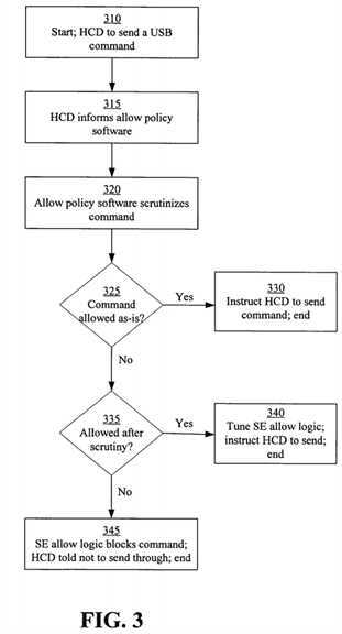
If at step?325, the allow policy software?240?determines that the SE allow logic?277?should be programmed to allow the command to go through, then at step?335, the allow policy software?240?determines if the command is allowed under the circumstances and consistent with a predetermined security policy. If the command is allowed to be sent to the device, then at step?340, the allow policy software?240?tunes the settings of the SE allow logic?277?so that the command can go through and instructs the HCD?210?to send the command. For example, the SE allow logic?277?can be programmed such that a Set_Address command going to device address 0 (which is the default address) on the host controller port number 3 can go through. If at step?335, the allow policy software?240?determines that the command is not allowed through to the device, then the SE allow logic?277?is programmed to block the command and the HCD?210?is instructed not to send the command.
It is understood that it is possible for malicious software to obtain data transferred between the allow policy software?240?and the HCD?210?in the area outside the trusted execution environment?211. An adversary could cause the HCD?210?to perform an operation that is different than the instructions of the allow policy software?240. For example, when the allow policy software?240?instructs the HCD?210?that a certain command cannot be sent to the device, malicious software can cause the HCD?210?to send the command anyway. Because the allow policy software?240?has already programmed the SE allow logic?277?to block the command, however, the hardware will prevent the command from being sent.
Substitution attacks can be mitigated if the USB topology?282?remains accurate. As described herein, a substitution attack involves substituting an illegitimate USB device for a legitimate device without the system recognizing that a substitution occurred. Keeping track of the USB topology?280?by interacting with the HCD?260?alone may not ensure trustworthiness because a malicious driver can interfere with this interaction. Using a system with an SE?265?and a trusted execution environment?220?makes it possible to maintain a topology map that matches the physical bus topology?280.
To properly track changes to the USB topology?280, the SE allow logic?277?may be programmed by the trusted software such as the SE driver?225?or the allow policy software?240?contained in the SE driver?225. This may ensure that certain rules are enforced by the SE?265. One such rule is that any USB command sent to the default address must go through the allow policy software?240?so that the hardware of the SE allow logic?277?can be programmed to "allow" the command to go through. A second rule is that a USB command sent to a hub in the USB topology?280?goes through the allow policy software?240?so that the SE allow logic?277?can be programmed to "allow" the command to go through. By applying these and any other appropriate rules, USB commands that might have an impact on the USB topology?280?are evaluated and "allowed" by the allow policy software?240.
The allow policy software?240, therefore, infers a state of the actual USB topology?280?by monitoring the relevant USB commands. In this way, the allow policy software?240?will know when there has been a physical change (i.e., when a USB device is either plugged in or out of a port) to the USB topology280.
The allow policy software?240?monitors and detects topology changes differently, depending on the type of change. For example, in one embodiment of the invention, a USB device may be attached to an external hub port. When this happens, the allow policy software?240?may look at a "Port_Reset" or similar command that the hub driver?206?sends to the hub device in the USB topology?280. Later on, when the allow policy software?240?sees a command sent to the default address (address 0), it knows that the device at the default address is connected to the hub that previously reset its port.
In an alternative embodiment of the invention, a USB device may be detached from an external hub port. The allow policy software?240?may not immediately detect this, as the hub driver?208?may not send any USB commands to its hub when it detects that a device was disconnected. When a USB command that queries the port‘s status, however, is sent to the hub, the allow policy software?240?can detect that the status of one of the ports changed, and it can therefore infer that whatever was connected to that port before is gone.
In yet another embodiment, a device may be attached to a root hub port. The allow policy software?240?will evaluate a USB command sent to the default address (address 0). At that point, the host controller chipset?255?is queried for its root ports‘ status. If one of the ports was reset, this means that the newly attached device is connected to that port. It is understood that the allow policy software?240?queries the host controller chipset?255?using the SE programmable interface?270, so the operation is trustworthy.
Likewise, when detaching a device from a root hub port, the allow policy software?240?may not immediately detect the change until a device is connected to that port, in which case the steps outlined with regard to attaching a device to the root hub are performed.
Because the USB topology?280?is dynamic, the allow policy software?240?may reprogram the SE allow logic?277?when changes in the USB topology280?require the settings to change. This generally happens when hubs are added to or removed from the USB topology?280. The SE allow logic?277?is updated with the hub addresses so that when a USB command is sent to a hub, it is blocked by the SE allow logic?277?unless it was previously "allowed."
FIG. 4 is a flow diagram of an example method?400?for controlling delivery of USB commands regarding cryptographic keys according to the invention. The method?400?is described with regard to using an allow policy for key exchange. At step?410, the SE allow logic?277?is programmed such that any USB command sent to a USB device from which a key should be read is blocked unless the command is specifically "allowed" by the allow policy software?240. Once the SE allow logic?277?is programmed, any USB commands sent to the device are evaluated by the allow policy software?240. At step?420, the allow policy software?240?scrutinizes the command after the USB command for fetching the key is sent to the USB device.
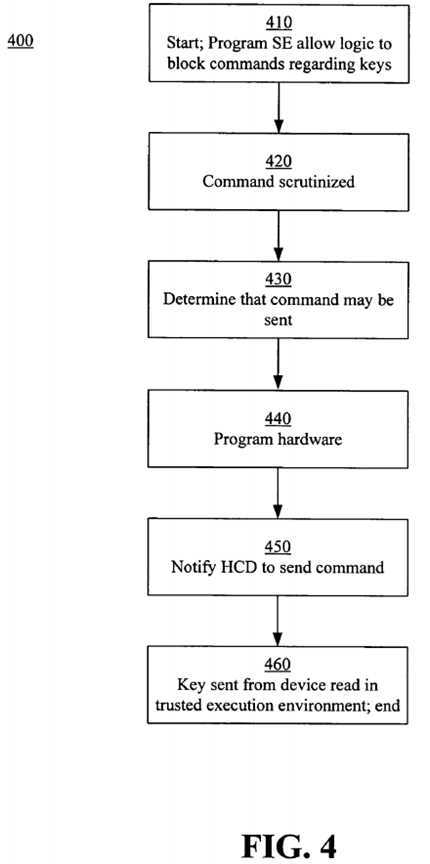
At step?430, the allow policy software?240?determines that the command is allowed and, it programs the SE allow logic?277?at?440?to allow the command through to the topology?280?and the applicable device. If the allow policy software?240?determines alternatively that the command may not be sent, then the hardware of the SE?265?(e.g., the SE allow logic?277) is not altered and, if malicious software attempts to send the command, the command will be blocked by the hardware. At step?450, the allow policy software?240?sends the command to the HCD?210?for delivery to the device. Additionally, the hardware is instructed to divert any data returned from the device to the SE buffer?275?and to send the USB host controller chipset?255substitute data so that the transaction can be completed properly. At step?460, trusted software executing in the trusted execution environment?220?can access the SE buffer?275?and read the key sent through the USB host controller chipset?255?by the device. Because the data can only be read by trusted software, malicious software running on the host?200?does not have access to it.
FIG. 5 is a flow diagram of an example method?500?for auditing a USB topology?280, according to the invention. The USB topology audit, whether completed through the example method?500?or other methods, verifies that the USB topology managed by the HCD?210?matches the actual USB topology?280. Because the HCD?210?is in the area outside the trusted execution environment?211, the topology map it manages may not be trustworthy. Through the method?500, the trusted audit manager?239?maintains a trusted topology map?237?with information such as to which hub a certain device is connected. In addition, the USB topology audit method?500?detects input devices, such as keyboards or mice, in the actual USB topology?280?and marks the input devices as trusted input devices after appropriate verification.
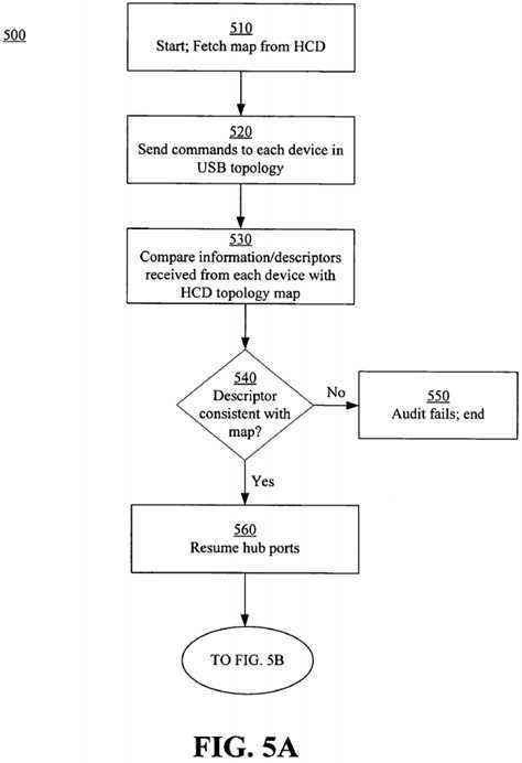
At step?510, the trusted audit manager?230?fetches the topology map managed by the HCD?210. After the trusted audit manager?230?obtains the map, it sends USB commands to all the devices in the actual USB topology?280?at step?520. The commands ensure that the type of each device matches information in the topology map fetched from the HCD?210. For example, when a USB hub is found in the actual USB topology?280, a USB command is sent to that hub to fetch certain USB descriptors. At step?530, descriptors or any other information sent by each device to the trusted audit manager?230are scrutinized to ensure that the descriptors match the type of device indicated on the topology map. It will be understood that, to fetch the descriptors in a trustworthy fashion, the trusted audit manager?230?programs the SE?265?so that the returned descriptors are put in the SE buffer?275. Because the SE buffer?275?is only accessible to trusted software, such as the trusted audit manager?230, the descriptors are protected from malicious software running outside the trusted execution environment?220.
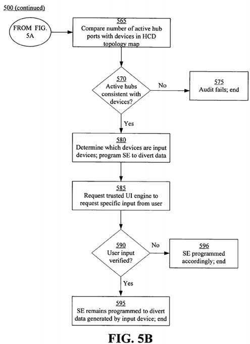
If at step?540, the trusted audit manager?230?determines that the descriptor for a device does not match the type of device indicated on the topology map, then at step?550, the audit fails and appropriate notifications are made. If at step?540, the trusted audit manager?230?determines that the descriptors match, then the trusted audit manager?230?next sends a command to resume all hub ports at step?560. The trusted audit manager?230resumes suspended hub ports to ensure that the USB topology?280?has not been attacked through use of a USB device that is hidden by suspending a port on a hub to which the device is connected. At step?565, the trusted audit manager sends appropriate commands to ensure that the number of USB devices (i.e., hubs and functions) in the HCD‘s topology map equals the number of active hub ports in the USB topology?280. Additionally, to determine the number of active ports on the root hub of the host controller chipset?255, the trusted audit manager?230?accesses certain registers within the SE?265registers that contain this information. If, at step?570, the number of active ports of the hubs is not equal to the number of USB devices, then the HCD‘s topology map does not match the actual USB topology?280. Thus, the audit fails at step?575?and appropriate actions are taken.
If the number of active ports is equal to the number of USB devices, the trusted audit manager?230?next performs steps to secure appropriate input devices. The trusted audit manager secures input devices that generate input data that the SE?265?diverts to the SE buffer?275. Because the trusted audit manager?230?can differentiate between hubs and functions in the USB topology?280, at step?580, it further examines the USB descriptors of the functions to find all the input devices. The SE?265?is programmed to divert data generated by the input devices to the SE buffer?275?for scrutiny by the trusted execution environment?220. It is understood, however, that determining devices that are, for example, keyboards or mice may not be enough, as USB devices may be maliciously programmed to look like input devices.
Therefore, the trusted audit manager?230?requests a user to actually generate data from the device in question. To examine user-provided input, at step585, the trusted audit manager?230?asks the trusted UI engine?230?to display a trusted UI element on a display screen of the system?200. The trusted UI element requests the user to, for example, type a specific word or sequence of characters with the keyboard or to move the mouse to a certain location and clicking a mouse button. At step?590, the trusted audit manager?230?access the SE buffer?275?and examines data generated by the device to verify that the user generated the appropriate data. If the verification fails, then the device is no longer trusted and at step?596, the SE?265?is programmed so that input generated by the device is not diverted to the SE buffer?275. If the verification shows a match, then at step?595, the SE?265remains programmed to divert data generate by the trusted device to the SE buffer?275.
FIG. 6 is a block diagram of an example system?600?for auditing a USB topology, according to the invention. The system?600?includes the trusted audit manager?230, USB host controller chipset?255?comprising a root hub?610, described with regard to FIG. 2, USB hubs?681,?685,?686, and USB functions682,?683,?684,?687,?688. As described with regard to the method?500, after the trusted audit manager?230?fetches the HCD‘s topology map, the trusted audit manager?230?sends commands to the hubs?610,?681,?685,?686?and functions?682,?683,?684,?687,?688?based on their USB addresses to fetch descriptors. This is completed after the SE?265?is programmed to divert data returned from the USB devices to the SE buffer?275. The trusted audit manager?230?accesses the SE buffer?275?and obtains the descriptors of each device in order to make sure that the device type is correct. For example, when a Get_Descriptor command is sent to USB hub #1?681, the returned descriptor should indicate that the device is indeed a hub. The trusted audit manager?230?then resumes the ports on the hubs?681,?685,?686?to ensure no ports are suspended. This is done by sending the appropriate USB command to the hubs?681,?685,?686.
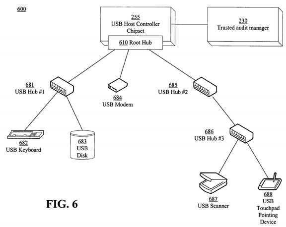
The trusted audit manager?230?counts the active ports on all the hubs?610,?681,?685,?686?in the topology. In the system?600, the trusted audit manager230?determines that eight ports are active, the respective ports for the three hubs?681,?685,?686?and the five functions?682,?683,?684,?687,?688. Assuming that the topology map fetched from the HCD?210?contains information indicating that eight ports are active, then the audit is successful.
Finally, the trusted audit manager?230?secures the input devices, namely a keyboard?682?and a touchpad pointed device?688. The trusted audit manager?230?programs the SE?265?to divert input data from these devices?682,?688?to the SE buffer?275. The trusted UI engine?230?is asked to display a certain UI element using which the user should generate some input data using these devices?682,?688. The trusted audit manager accesses the SE buffer?275?and examines the data generated by the devices?682,?688. If the data matches what the trusted audit manager expected, then it is concluded that a user generated input using the devices?682,?688, as opposed to a malicious device generating the input. The devices?682,?688?are properly secured using the SE?265?hardware. If there is a mismatch, then it might mean that an adversary has manipulated a programmable USB device and made it look like, for example, the keyboard?682. In this case, the trusted topology audit fails and the SE?265?will not be programmed to treat these devices?682,?688?as "trusted."
SRC=http://www.freepatentsonline.com/7761618.html
Using a USB host controller security extension for controlling changes in and auditing USB topology
标签:des style blog http color io os ar strong
原文地址:http://www.cnblogs.com/coryxie/p/3998616.html