标签:fda 信息 注销 信息保存 通过 each ret 计算 时间
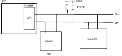
I2C:数据线和时钟线。
起始信号:时钟线为高电平,数据线由高到低跳变。
结束信号:时钟线为高电平,数据线由低到高跳变。
应答信号:第九个时钟周期,时钟线保持为高电平,数据线为低电平,此时为成功应答。
读写位:站在主机的角度考虑。
0代表主机给从机发送数据。
1代表主机接收从机的数据。
硬件原理:
数据帧的封装:
主机给从机发送数据:
起始信号 + 7位从机地址 写位 + 从机给主机应答 + 主机给从机发送8位数据
+ 从机给主机应答 ... + 主机给从机发送8位数据 + 从机给主机应答 + 结束信号。
主机读取从机数据:
起始信号 + 7位从机地址 读位 + 从机给主机应答 + 从机给主机发送数据 +
主机给从机应答 + ..... + 结束信号
主机先写数据再读数据:
起始信号 + 7位从机地址 写位 + 从机给主机应答 + 主机给从机发送数据 + 从机给主机应答 ...
+ 起始信号 + 7位从机地址 读位 + 从机给主机应答 ... + 结束信号。
具体的读写数据帧应该去查看芯片手册中的读写时序。
MPU6050时序:
to write the internal MPU-60X0 registers, the master transmits the start condition (S), followed by the I 2 C address and the write bit (0). At the 9 th clock cycle (when the clock is high), the MPU-60X0 acknowledges the transfer. Then the master puts the register address (RA) on the bus. After the MPU-60X0 acknowledges the reception of the register address, the master puts the register data onto the bus. This is followed by the ACK signal, and data transfer may be concluded by the stop condition (P).
写时序:S + 从机地址 0(写) + ACK + 从机的寄存器地址 + ACK + 寄存器数据 + ACK + P
注:封装数据帧时从机地址不是数据,从机的寄存器地址为数据。
To read the internal MPU-60X0 registers, the master sends a start condition, followed by the I 2 C address and a write bit, and then the register address that is going to be read. Upon receiving the ACK signal from the MPU-60X0, the master transmits a start signal followed by the slave address and read bit. As a result, the MPU-60X0 sends an ACK signal and the data. The communication ends with a not acknowledge (NACK) signal and a stop bit from master.
读时序:S + 从机地址 0 (写)+ ACK + 主机将要读取的寄存器地址 + ACK + 起始信号 + 从机地址 1(读)+ ACK + 数据 + 非应答 + 结束信号
注:主机从从机读取数据前要告诉从机要读哪个寄存器的数(写),然后从机将数据保存到某个地方供给主机去读取数据。
内核中的I2C子系统:
总线驱动层:厂家实现的,总线驱动层知道如何操作数据,但是不知道操作哪些数据。
核心层:承上启下,提供接口实现设备和总线数据交互
设备驱动层:自己实现,设备驱动知道操作哪些数据,但是不知道如何操作数据。
核心点:设备驱动中一定需要封装数据,交给总线驱动。
i2c总线的驱动结构体:
1 struct i2c_driver
2 {
3     int (*probe)(struct i2c_client *, const struct i2c_device_id *);//如果设备和驱动匹配成功,则执行probe函数。
4     int (*remove)(struct i2c_client *);
5     struct device_driver driver;
6     const struct i2c_device_id *id_table;
7 };
1 struct device_driver
2 {
3     const char *name;//可以用来匹配,主要用来在/sys/bus/i2c/drivers目录下创建文件夹
4     const struct of_device_id *of_match_table;//用来和设备树匹配。
5 };
1 struct i2c_device_id
2 {
3     char name[];//专门用来和设备匹配,但是i2c总线这个位置特殊,这个字符串必须存在。和i2c_client中的name比较结果成立不成立无所谓。
4 };
1 struct i2c_client {//描述i2c的设备信息(并不是真正的设备信息)
2     unsigned short flags;//代表读写位
3     unsigned short addr;//从机地址
4     char name[I2C_NAME_SIZE];//字符串,如果使用设备树不用于匹配。
5     struct i2c_adapter *adapter;//指向了正在使用的i2c适配器
6 };
7 //设备树转化成c代表后先将信息保存到struct i2c_board_info中,再将struct i2c_board_info内容复制到i2c_client中。
I2C驱动接口:
1 i2c_add_driver();//注册驱动
2 i2c_del_driver();//注销驱动
内核源码分析:
 1 进入i2c的总线驱动层:
 2 vi drivers/i2c/busses/i2c-s3c2410.c
 3 控制了起始状态,从机地址,读写位,使能了应答位,提供了读写数据的方法。
 4
 5 进入i2c的核心层:
 6 vi drivers/i2c/i2c-core.c
 7 static int __init i2c_init(void)
 8  {
 9      retval = bus_register(&i2c_bus_type);
10     i2c_adapter_compat_class = class_compat_register("i2c-adapter");
11     retval = i2c_add_driver(&dummy_driver);
12 }
13
14 -->#define i2c_add_driver(driver),i2c_register_driver(THIS_MODULE, driver)
15
16 struct bus_type i2c_bus_type = {
17      .name = "i2c",
18      .match = i2c_device_match,
19      .probe = i2c_device_probe,
20  };
21
22
23 --> res = driver_register(&driver->driver);
24
25
26 -->other = driver_find(drv->name, drv->bus);//查找i2c的某个名称的驱动是否被注册
27     ret = bus_add_driver(drv);//如果没有被注册,我们才可以注册
28
29
30 -->error = driver_attach(drv);
31
32
33 -->return bus_for_each_dev(drv->bus, NULL, drv, __driver_attach);
34
35
36 --> if (!driver_match_device(drv, dev))
37
38
39 --> return drv->bus->match ? drv->bus->match(dev, drv) : 1;
40
41
42 --> struct bus_type i2c_bus_type = {
43         .name = "i2c",
44         .match = i2c_device_match, //提供匹配方法
45 };
46     driver_probe_device(drv, dev);
47
48
49 -->ret = really_probe(dev, drv);
50
51
52 --> if (dev->bus->probe) {
53 --> ret = dev->bus->probe(dev);
54 执行i2c_bus_type中的probe接口
55
56
57 -->status = driver->probe(client, i2c_match_id(driver->id_table, client))
58 //自己封装的probe接口
I2C设备树添加:
 1 vi exynos4412-origen.dts:
 2 i2c@13860000 {//描述i2c总线
 3     #address-cells = <1>;
 4     #size-cells = <0>;
 5     samsung,i2c-sda-delay = <100>;
 6     samsung,i2c-max-bus-freq = <20000>;
 7     pinctrl-0 = <&i2c0_bus>;
 8     pinctrl-names = "default";
 9     status = "okay";
10
11     s5m8767_pmic@66 { //描述i2c从机设备
12         compatible = "samsung,s5m8767-pmic";
13         reg = <0x66>;
14 ..................
15 };
-------->>>>>
查看原理图找到I2C_SDA5 I2C_SCL5,说明使用的是I2C总线控制器5
查看芯片手册I2CCONn 对应的地址:0x13860000 0x13870000 ......
自己的I2C总线控制器节点:
 1 i2c@138B0000
 2 {
 3     #address-cells = <1>;
 4     #size-cells = <0>;
 5     samsung,i2c-sda-delay = <100>;//三星平台下i2c总线的数据线高低电平跳变延时时间为100ns
 6     samsung,i2c-max-bus-freq = <100000>;//三星平台下,i2c总线的数据输出速率为100kbit/s
 7
 8     pinctrl-0 = <&i2c5_bus>;
 9     pinctrl-names = "default";
10
11     status = "okay";//当前总线的状态为可用状态
12     mpu6050@68{
13         compatible = "fs4412,mpu6050";
14         reg = <0x68>;
15 };
16 };
pinctrl-0 = <&i2c0_bus>;
pinctrl-1 = <&b>;b索引的引脚必须是idle状态
pinctrl-2 = <&c>;c索引的引脚必须是sleep状态
pinctrl-names = "default","idle","sleep";//代表了当前节点使用的引脚状态为默认状态。
//代表了当前节点使用的引脚状态为空闲状态。
//代表了当前节点使用的引脚状态为深度睡眠状态。
i2c5_bus索引一个设备树节点,节点中会有一组指定的引脚。
1 vi exynos4x12-pinctl.dtsi
2 i2c5_bus: i2c5-bus {
3     samsung,pins = "gpb-2", "gpb-3";//指定使用了GPBCON对应的一组寄存器
4     samsung,pin-function = <3>;//指定GPBCON [2]和[3]值为3,描述数据线和时钟线
5     samsung,pin-pud = <3>;//将GPBPUD设置为使能上拉
6     samsung,pin-drv = <0>;//操作了GPBDRV寄存器,值为0,使用1倍电流强度
7 };
mpu6050:
功能:加速度计(x,y,z三轴的值)、角速度计(x,y,z三轴的值)、温度计
1 int i2c_transfer(struct i2c_adapter *adap, struct i2c_msg *msgs, int num) //间接调用i2c总线驱动(通过核心层)
1 //封装数据帧结构体
2 struct i2c_msg {
3      __u16 addr; //从机地址
4      __u16 flags;//读写位
5      __u16 len;//读或者写的数据字节数
6      __u8 *buf;//读:用来存放数据 写:存放需要写入的数据
7 };
8 //有几个起始信号就有几个i2c_msg结构体,所以这个通常是一个结构体数组
封装写时序:
S + 从机地址 0 + 成功应答 + 从机的寄存器地址 + 成功应答 + 寄存器数据 + ACK + P
读时序:
S + 从机地址 0 + ACK + 主机将要读取的寄存器地址 + ACK + S + 从机地址 1 + ACK + 数据 + 非应答 + 结束信号
mpu6050参考代码:

 1 #ifndef _HEAD_H_
 2 #define _HEAD_H_
 3
 4 //控制类寄存器,往以下寄存器中写入实验值
 5 #define SMPLRT_DIV  0x19    //采样率分频,典型值:0x07(125Hz) */
 6 #define CONFIG   0x1A       // 低通滤波频率,典型值:0x06(5Hz) */
 7 #define GYRO_CONFIG  0x1B   // 陀螺仪自检及测量范围,典型值:0x18(不自检,2000deg/s) */
 8 #define ACCEL_CONFIG 0x1C  // 加速计自检、测量范围及高通滤波频率,典型值:0x01(不自检,2G,5Hz) */
 9 #define PWR_MGMT_1  0x6B // 电源管理,典型值:0x00(正常启用) */
10
11 //数据类寄存器,读出以下寄存器的内容,给应用层传递
12 #define TEMP_OUT_H  0x41   // 存储的最近温度传感器的测量值 */
13 #define TEMP_OUT_L  0x42
14
15 #define GYRO_XOUT_H  0x43 // 存储最近的X轴、Y轴、Z轴陀螺仪感应器的测量值 */
16 #define GYRO_XOUT_L  0x44
17 #define GYRO_YOUT_H  0x45
18 #define GYRO_YOUT_L  0x46
19 #define GYRO_ZOUT_H  0x47
20 #define GYRO_ZOUT_L  0x48
21
22 #define ACCEL_XOUT_H 0x3B  // 存储最近的X轴、Y轴、Z轴加速度感应器的测量值 */
23 #define ACCEL_XOUT_L 0x3C
24 #define ACCEL_YOUT_H 0x3D
25 #define ACCEL_YOUT_L 0x3E
26 #define ACCEL_ZOUT_H 0x3F
27 #define ACCEL_ZOUT_L 0x40
28
29 //封装联合体
30 union mpu6050
31 {
32     //加速度
33     struct mpu6050_accel
34     {
35         unsigned short x;
36         unsigned short y;
37         unsigned short z;
38     }accel;
39     //角速度
40     struct mpu6050_gyro
41     {
42         unsigned short x;
43         unsigned short y;
44         unsigned short z;
45     }gyro;
46     //温度
47     unsigned short temp;
48 };
49 //命令的封装
50 #define ACCEL_CMD     _IOR(‘x‘,0,union mpu6050)
51 #define GYRO_CMD     _IOR(‘x‘,1,union mpu6050)
52 #define TEMP_CMD     _IOR(‘x‘,2,union mpu6050)
53
54 #endif
 1 #include <stdio.h>
 2 #include <sys/types.h>
 3 #include <sys/stat.h>
 4 #include <fcntl.h>
 5 #include <sys/ioctl.h>
 6 #include "head.h"
 7
 8 int main(int argc, const char *argv[])
 9 {
10     int fd;
11
12     fd = open("/dev/mpu6050",O_RDWR);
13
14     union mpu6050 data;
15     while(1)
16     {
17         ioctl(fd,ACCEL_CMD,&data);
18         printf("ACCEL:x = %d,y = %d,z = %d\n",data.accel.x,data.accel.y,data.accel.z);
19
20         ioctl(fd,GYRO_CMD,&data);
21         printf("GYRO:x = %d,y = %d,z = %d\n",data.gyro.x,data.gyro.y,data.gyro.z);
22
23         ioctl(fd,TEMP_CMD,&data);
24         printf("TEMP:%d\n",data.temp);
25         sleep(1);
26     }
27     return 0;
28 }
  1 #include <linux/init.h>
  2 #include <linux/module.h>
  3 #include <linux/fs.h>
  4 #include <linux/i2c.h>
  5 #include <linux/device.h>
  6 #include <asm/uaccess.h>
  7 #include "head.h"
  8
  9
 10
 11 int major;
 12 struct class *cls;//定义设备类结构体
 13 struct device *devs;//定义设备文件结构体
 14 struct i2c_client *glo_client;//定义描述i2c的设备信息结构体
 15
 16 void write_data(unsigned char reg,unsigned char val)
 17 {
 18     char wbuf[2] = {reg,val};
 19     //根据mpu6050手册封装写时序
 20     // S + 从机地址 0 + 成功应答 + 从机的寄存器地址 +
 21                         //成功应答 + 寄存器数据 + ACK + P
 22     //有几个起始信号就有几个i2c_msg结构体,
 23     struct i2c_msg msg[1] = {//1代表着开始位的个数
 24         {
 25             .addr = glo_client->addr,//client结构体中存放了其从机的物理地址
 26             .flags = 0,//0位写数据,1为读时序
 27             .len = 2,//写的数据的字节数(从机寄存器地址+寄存器数据)
 28             .buf = wbuf,//写入到wbuf中
 29         },
 30     };
 31     //间接调用i2c总线驱动
 32     i2c_transfer(glo_client->adapter,msg,ARRAY_SIZE(msg));//计算msg结构体的大小
 33 }
 34 //给应用层的read函数提供接口
 35 unsigned char read_data(unsigned char reg)
 36 {
 37     unsigned char rbuf[1];//从机将数据存到rbuf中供给主机读取数据
 38     unsigned char wbuf[1] = {reg};//主机将要读取的寄存器地址
 39     //S + 从机地址 0 +  ACK + 主机将要读取的寄存器地址 + ACK +
 40         // S + 从机地址 1 + ACK + 数据 + 非应答 + 结束信号
 41     //主机开始告诉从机要读哪个寄存器的数据,然后从机将寄存器数据存到rbuf中供给主机读取数据
 42     struct i2c_msg msg[2] = {
 43         {
 44             .addr = glo_client->addr,//获取从机的物理地址
 45             .flags = 0,//写
 46             .len = 1,//只写入一个地址8bit
 47             .buf = wbuf,
 48         },
 49         {
 50             .addr = glo_client->addr,
 51             .flags = 1,//读功能
 52             .len = 1,
 53             .buf = rbuf,
 54         },
 55     };
 56     i2c_transfer(glo_client->adapter,msg,ARRAY_SIZE(msg));//间接调用i2c总线驱动
 57     return rbuf[0];//将读取到的数据返回
 58 }
 59 //用于和设备树匹配
 60 struct of_device_id mpu6050_match_tbl[] = {
 61     {
 62         .compatible = "fs4412,mpu6050",
 63     },
 64     {},//不能省略否则可能出现段错误
 65 };
 66
 67 int mpu6050_open(struct inode *inode,struct file *filp)
 68 {
 69     return 0;
 70 }
 71
 72 //功能选择
 73 long mpu6050_ioctl(struct file *filp,unsigned int cmd,unsigned long arg)
 74 {
 75     int ret;
 76     union mpu6050 data;//定义联合体变量
 77     switch(cmd)
 78     {
 79     case ACCEL_CMD://加速的
 80         data.accel.x = read_data(ACCEL_XOUT_L);//数据第八位
 81         data.accel.x |= read_data(ACCEL_XOUT_H) << 8;//数据高8位|第8位 = 16位数据
 82         data.accel.y = read_data(ACCEL_YOUT_L);
 83         data.accel.y |= read_data(ACCEL_YOUT_H) << 8;
 84         data.accel.z = read_data(ACCEL_ZOUT_L);
 85         data.accel.z |= read_data(ACCEL_ZOUT_H) << 8;
 86         break;
 87     case GYRO_CMD://角速度
 88         data.gyro.x = read_data(GYRO_XOUT_L);
 89         data.gyro.x |= read_data(GYRO_XOUT_H) << 8;
 90         data.gyro.y = read_data(GYRO_YOUT_L);
 91         data.gyro.y |= read_data(GYRO_YOUT_H) << 8;
 92         data.gyro.z = read_data(GYRO_ZOUT_L);
 93         data.gyro.z |= read_data(GYRO_ZOUT_H) << 8;
 94         break;
 95     case TEMP_CMD://温度
 96         data.temp = read_data(TEMP_OUT_L);
 97         data.temp |= read_data(TEMP_OUT_H) << 8;
 98         break;
 99     }
100     //将数据拷贝到arg地址中供给应用层处理
101     ret = copy_to_user((void *)arg,&data,sizeof(data));
102     return 0;
103 }
104 //文件操作结构体
105 struct file_operations fops = {
106     .open = mpu6050_open,
107     .unlocked_ioctl = mpu6050_ioctl,
108 };
109
110 int mpu6050_probe(struct i2c_client *client,const struct i2c_device_id *id)
111 {
112     printk("match ok\n");
113
114     glo_client = client;
115
116     //字符设备框架搭建
117     major = register_chrdev(0,"mpu6050",&fops);
118     cls = class_create(THIS_MODULE,"mpu6050");
119     devs = device_create(cls,NULL,MKDEV(major,0),NULL,"mpu6050");
120
121     write_data(SMPLRT_DIV,0x07);//将特定数据写入到控制类寄存器中
122     write_data(CONFIG,0x06);
123     write_data(GYRO_CONFIG,0x18);
124     write_data(ACCEL_CONFIG,0x01);
125     write_data(PWR_MGMT_1,0x00);
126     return 0;
127 }
128
129 int mpu6050_remove(struct i2c_client *client)
130 {
131     return 0;
132 }
133 //和platform的区别是platform可以没有这个结构体但是I2C必须不能少
134 struct i2c_device_id mpu6050_id_tbl[] = {
135     {
136         .name = "xxx",//名字不重要
137     },
138 };
139
140 //定义i2c驱动结构体
141 struct i2c_driver mpu6050_pdrv = {
142     .driver = {
143         .name = "fs4412-mpu6050",
144         .of_match_table = mpu6050_match_tbl,
145     },
146
147     .probe = mpu6050_probe,//探测函数
148     .remove = mpu6050_remove,
149     //id_table不能省略!!!(和i2c_client中的name比较结果成立不成立无所谓)
150     .id_table = mpu6050_id_tbl,
151 };
152
153 #if 0
154 int mpu6050_init(void)
155 {
156     i2c_add_driver(&mpu6050_pdrv);
157     return 0;
158 }
159 module_init(mpu6050_init);
160
161 void mpu6050_exit(void)
162 {
163     i2c_del_driver(&mpu6050_pdrv);
164     return;
165 }
166 module_exit(mpu6050_exit);
167 #endif
168 //封装模块2要素函数接口包括注册和卸载i2c总线驱动
169 module_i2c_driver(mpu6050_pdrv);
170 MODULE_LICENSE("GPL");
标签:fda 信息 注销 信息保存 通过 each ret 计算 时间
原文地址:https://www.cnblogs.com/hslixiqian/p/9683082.html
