标签:引脚 芯片 int inf xtend mux 转换器 while hold
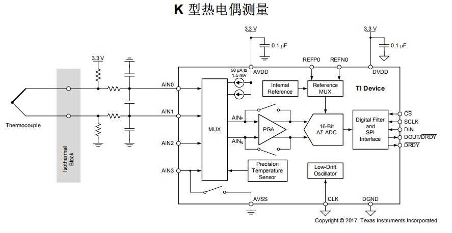
1. 先看下ADS1120的结构图,ADS1120是个比较奇葩的ADC模数转换器,因为比较适用于热电阻之类的温度采集器。看下图,有个MUX多路复用器,应该是选择两个差分信号去测试,通过输入多路复用器 (MUX) 实现的两个差分输入或四个单端输入,一个低噪声可编程增益放大器 (PGA),PGA,内部 PGA 提供高达128V/V 的增益。此 PGA 使得 ADS1120 非常适用于小型传感器信号测量 应用 ,例如电阻式温度检测器(RTD)、热电偶、热敏电阻和桥式传感器。
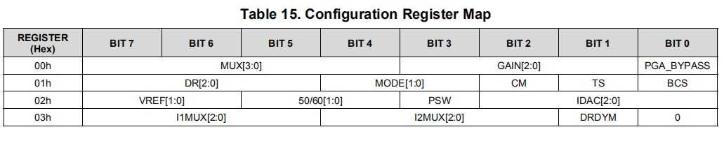
2. 看下寄存器,4个寄存器
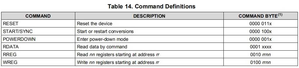
3. 命令
4. 参考例程
VOID main(VOID)
{
    signed long tData;
    WDTCTL = WDTPW + WDTHOLD;        // Stop watchdog timer
    Init_StartUp();                 // Initialize device
    ADS1220Init();                    // Initializes the SPI port pins as well as control
    ADS1220Config();                // Set base configuration for ADS1x20 device
    while(1)
    {
        /* Add specifc command for reading and writing ADS1220 here */
        /* dFlag is set in the interrupt service routine when DRDY triggers end
           of conversion */
        if (dflag)                        /* check if new data is available */
        {
            tData = ADS1220ReadData();    /* get the data from the ADS1220 */
            dFlag=0;
        }
        /* other routines could be added here, such as change the mux setting */
    }  /* end of while(1) */
} /* end of main() */
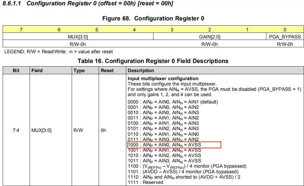
其中配置函数比较重要,如下是1增益,也是就不变,然后ADS1220_MUX_0_G=0x80
void ADS1220Config(void)
{
    unsigned Temp;
    ADS1220ReadRegister(ADS1220_0_REGISTER, 0x01, &Temp);
    /* clear prev value; */
       Temp &= 0x0f;
       Temp |= ADS1220_MUX_0_G;
       /* write the register value containing the new value back to the ADS */
       ADS1220WriteRegister(ADS1220_0_REGISTER, 0x01, &Temp);
    ADS1220ReadRegister(ADS1220_1_REGISTER, 0x01, &Temp);
    /* clear prev DataRate code; */
    Temp &= 0x1f;
    Temp |= (ADS1220_DR_600 + ADS1220_CC);        /* Set default start mode to 600sps and continuous conversions */
    /* write the register value containing the new value back to the ADS */
    ADS1220WriteRegister(ADS1220_1_REGISTER, 0x01, &Temp);
}
ADS1220_MUX_0_G=0x80,那么看下寄存器,什么意思呢?就是测量AIN0引脚的电平,得出一个结论,如果要想测量4个通道,那么需要依次次修改MUX[3:0],一个测量完再测试另外一个
读数据,这个例程比较简单,只测量了AIN0的电压,我们的应用是需要做2线PT100铂电阻温度测量,所以需要继续
long ADS1220ReadData(void)
{
   long Data;
   /* assert CS to start transfer */
   ADS1220AssertCS(1);
   /* send the command byte */
   ADS1220SendByte(ADS1220_CMD_RDATA);
   /* get the conversion result */

   Data = ADS1220ReceiveByte();
   Data = (Data << 8) | ADS1220ReceiveByte();
   /* sign extend data */
   if (Data & 0x8000)
      Data |= 0xffff0000;

   /* de-assert CS */
   ADS1220AssertCS(0);
   return Data;
}
标签:引脚 芯片 int inf xtend mux 转换器 while hold
原文地址:https://www.cnblogs.com/429512065qhq/p/10989382.html