标签:port psu 使用 har gns 技术 抓取数据 功能 conf
实验环境使用之前用过的GNS3、WireShark和CRT1、接下来用网线把PC和路由器连接起来
将PC1连到SW1的f1/0
将PC2连到SW1的f1/1
将SW1与SW2连到f1/2
将PC3连到SW2的f1/0
将PC4连到SW2的f1/1
设置好之后启动,然后显示全部端口。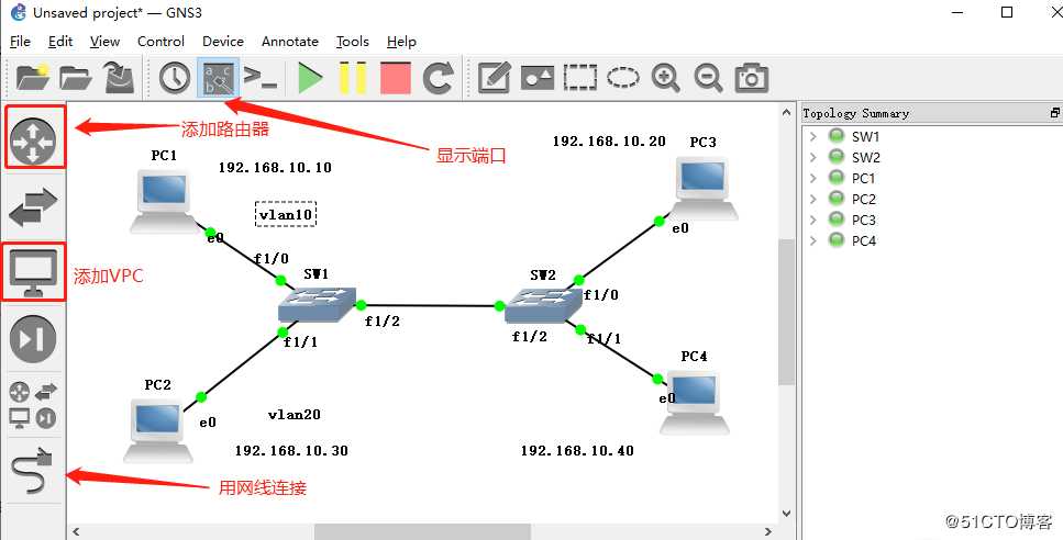
2、 将PC1和PC3划分在vlan10
将PC2和PC4划分在vlan20
配置PC1ip地址为192.168.10.10
配置PC2ip地址为192.168.10.30
配合pc3ip地址为192.168.10.20
配合PC3ip地址为192.168.10.40
3、配置完IP后进行互通,PC1可以和PC3互通,PC2可以和PC4互通,PC1不可以和PC2互通,PC3不可以和PC4互通。
4、双击打开SW1和SW2跳转至CRT界面进行配置:
SW1
输入conf t
输入no ip routing 关闭路由功能
输入vlan10,20添加路由
输入exit
输入do show vlan-sw b查看vlan
5、配置端口
SW1:
1、输入int f1/0
2、输入sw mo acc
3、输入sw acc vlan 10
4、输入exit
5、输入do show vlan-sw b
1、输入int f1/1
2、输入sw mo acc
3、输入sw acc vlan 20
4、输入do show vlan-sw b
1.输入conf t
2.输入no ip routing
3.输入vlan 10,20
4.输入ex
5.输入int f1/0
6.输入sw mo acc
7.输入sw acc vlan 10
8.输入ex
9.输入int f1/1
10.输入sw mo acc
11.输入sw acc vlan 20
12.输入do show vlan-sw b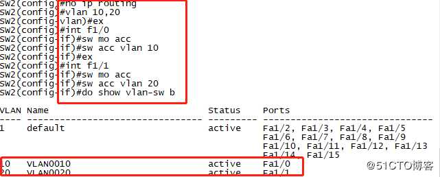
6、配置中继链路,在没有设置之前活跃在vlan1中。
输入ex
输入end进入特权模式
输入show int f1/0 switchport,查看端口,此时端口在access状态
7、接下来把SW1和SW2设置为中继链路。
SW1
输入conf t
输入switchport mode trunk 设置为trunk模式
输入switchport trunk encapsulation dot1q封装dot1q模式
输入ex
输入do show int f1/2 switchport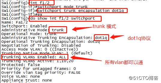
SW2:
输入int f1/2
输入switchport mode trunk设置为trunk模式
输入switchport trunk encapsulation dot1q模式
输入ex
输入do show int f1/2 switchport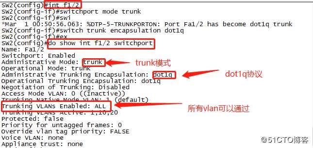
1、此时我们用PC1ping PC3是可以通的,PC2和PC4是可以互通的。
在PC1上输入ping 192.168.10.20,时可以通的
2、在PC2上输入192.168.10.40,也是可以通的
证明实验成功了。
此时我们可以用WireShark来抓互相通讯的数据分析
1、右击选择一条接入链路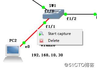
2、会从SW1 的f1/1的端口抓取数据,输入ping 192.168.10.40,抓包会获取数据。

3、双击从中获取的数据,其中有许多重要的数据。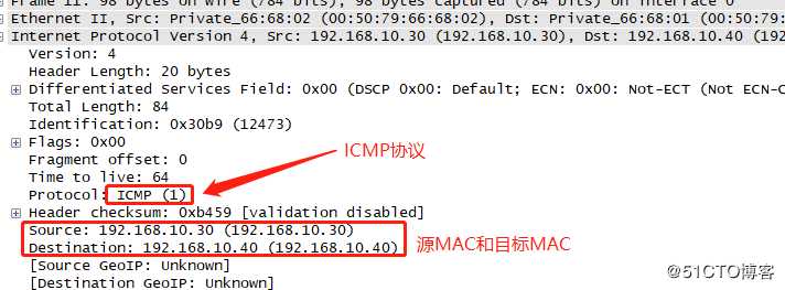
4、接下来我们抓取中继链路查看vlan。
5、再用PC2ping 192.168.10.40,从WireShark中抓取一个数据。

6、抓取一条从中查看,会看到一条802.1q vlan 20。
7、同时再抓取一条PC1与PC3的数据,用同样的方法打开数据查看。
8、这样不同链路才实现了互通。
标签:port psu 使用 har gns 技术 抓取数据 功能 conf
原文地址:https://blog.51cto.com/14307755/2428156