标签:connected 内容 network bsp font style image 目的 pac
使用Packet Tracer,正确配置网络参数,使用命令查看和分析RIP路由信息。
网络拓扑图如下图所示:

(1)配置客户端PC0的IP地址(这里是192.168.1.95)

配置客户端PC1的IP地址(这里是192.168.3.96)

(2)配置并激活路由器接口:
Router0接口:


检查:show ip interface brief

配置路由器协议:

查看路由表:show ip route

C 192.168.1.0/24 is directly connected, FastEthernet0/0:
192.168.1.0是直连网段,24是255.255.255.0的缩写,要转发数据包到192.168.1.0网段,通过 Fastethernet0/0接口转发。
R 192.168.3.0/24 [120/1] via 192.168.2.96, 00:00:25, FastEthernet0/1:
192.168.3.0/24是目标网络,[120/1]是管理距离及跳数,192.168.2.96是下一跳的IP地址,00:00:25是等待更新的时间。
Router1接口:


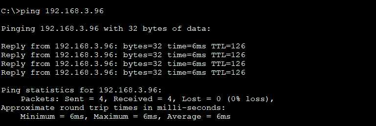
任意两台机器能ping成功,在PC0,PING PC1,测试整条链路的连通性
打开PC0的Command Prompt 输入ping+PC1的地址,如下图所示:
show ip protocols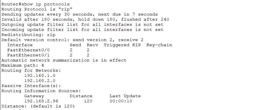
Routing Protocol is "rip":路由协议为RIP协议
FastEthernet0/0 2 2 :FastEthernet0/0发送和接受的版本为2
Maximum path: 4:最大路径:4
Routing for Networks: 192.168.1.0 192.168.2.0:路由器通告的网络为192.168.1.0和192.168.2.0
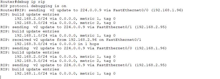
3.5 Debug
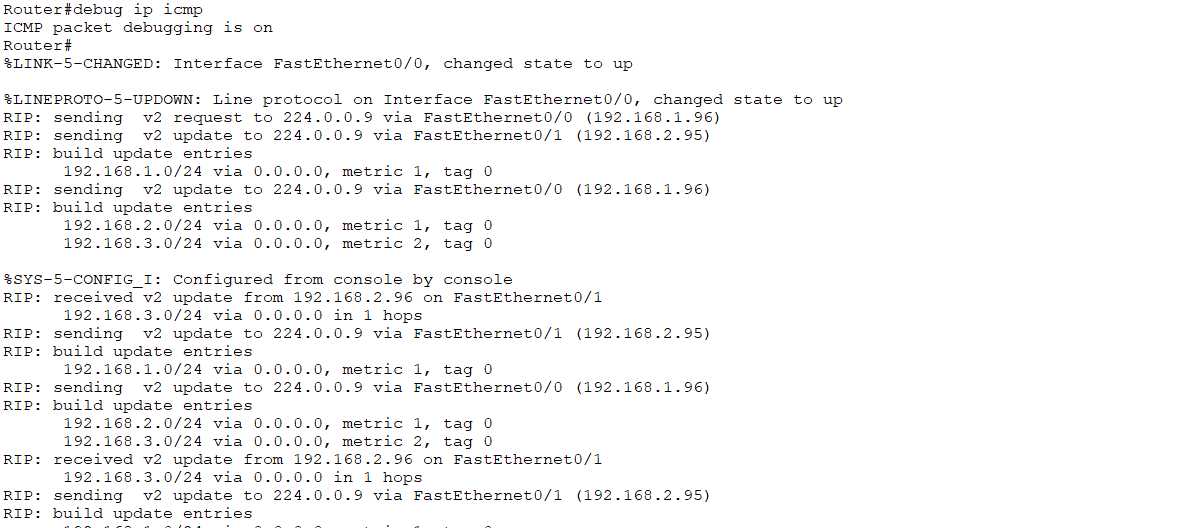
debug ip rip 查看发送和接受RIP报文
undebug all 停止调试输出

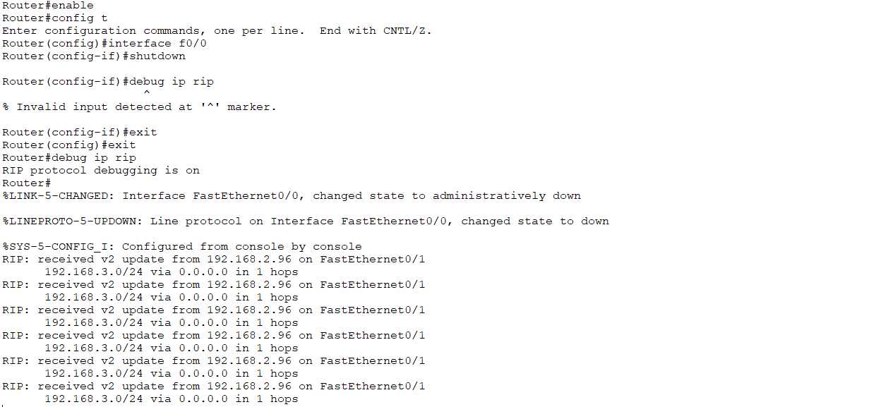
关掉R1的f0/0:shutdown
在R1查看RIP报文:debug ip rip
5.拓展
通过ping抓取ICMP报文,并分析
第四次实验报告:使用Packet Tracer理解RIP路由协议
标签:connected 内容 network bsp font style image 目的 pac
原文地址:https://www.cnblogs.com/end1/p/11762294.html