码迷,mamicode.com
首页 > 其他好文 > 详细

触发器链的应用——同步器与边沿检测电路

时间:2020-04-13 14:04:31      阅读:106      评论:0      收藏:0      [点我收藏+]

标签:init   one   put   set   使用   out   16px   size   种类型   


主要内容

  • 多级延迟触发器电路
  • 同步器
  • 边沿检测电路
  • 与移位寄存器的区别

1、多级延迟触发器电路

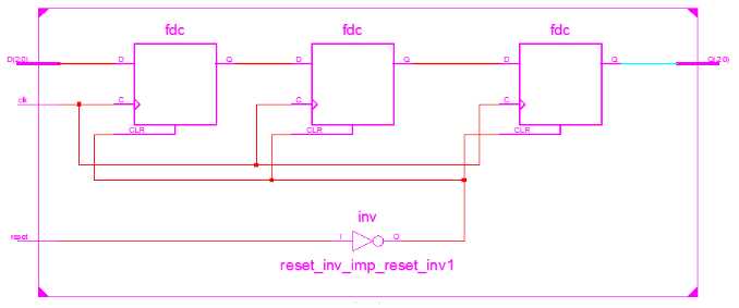
定义:是多个触发器串联组合,每进行一次传输,数据就延迟一个周期。可以通过增加触发器的数量来决定延时的拍数。

module    DFF_N #(parameter N=3)(
    input                         clk,
    input                         reset,
    input             [N-1:0]     D,
    output    reg     [N-1:0]     Q
);
    reg    [N-1:0]        d0;
    reg    [N-1:0]        d1;

    always @(posedge clk or negedge reset)
        if(!reset)
            begin
                d0 <= 0;
                d1 <= 0;
                Q   <= 0;
            end
        else
            begin
                d0 <= D;
                d1 <= d0;
                Q   <= d1;
            end

endmodule

上述代码中d0是输入信号D延迟一级采样或称为延迟一拍的信号,以此类推d1是延迟两拍信号,Q是延迟三拍信号。可以通过修改N来确定信号的位宽,和修改部分代码决定延迟的拍数。
技术图片


作用:使用如上延迟触发器链可以对D信号进行延吃操作。

2、同步器

同步器的两种类型:见https://www.cnblogs.com/lizhiqing/p/12059436.html

3、边沿检测电路

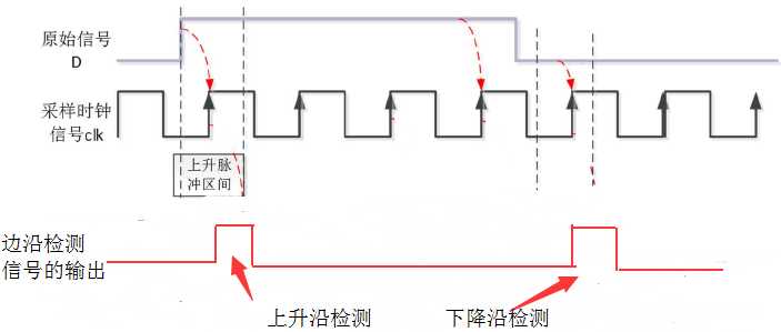
定义:待检测的信号的上升沿或者下降沿到来时,会输出一个脉冲信号。

技术图片

检测方法:

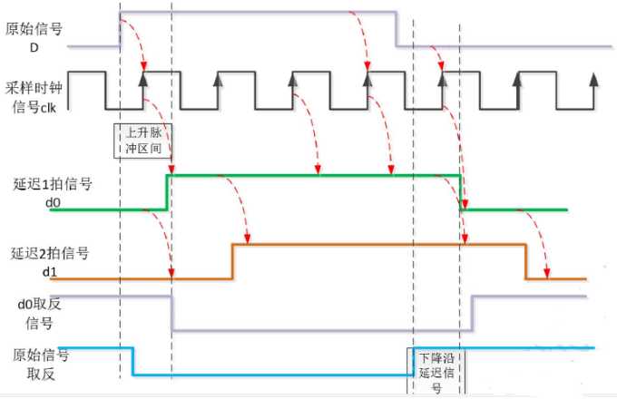
  • 上升沿:原始信号与延迟一拍的信号d0的反向信号
  • 下降沿:原始信号取反,与延迟一拍的信号d0

如果担心采样不稳定,可以使用d1代替d0。

技术图片


技术图片
module side_detect #(parameter  N=1)(
        input                   clk,
        input                   reset,
        input           [N-1:0] D,
        output          [N-1:0] D_rising_edge,
        output          [N-1:0] D_falling_edge,
        output  reg     [N-1:0] Q
);
    reg [N-1:0] d0;
    reg [N-1:0] d1;
    
    always @(posedge clk or negedge reset)
        if(!reset)
            begin
                d0 <= 0;
                d1 <= 0;
                Q  <= 0;
            end
        else
            begin
                d0 <= D;
                d1 <= d0;
                Q  <= d1;
            end
    assign  D_rising_edge = D & ~d0;
    assign  D_falling_edge = ~D & d0;
endmodule
边沿检测
技术图片
module tb_edge_dec #(parameter N=1)();
    wire     D_rising_edge;
    wire     D_falling_edge;
    wire     Q;
    reg             clk;
    reg             reset;
    reg             D;
    
    side_detect inst_edge(
    .clk                (clk),
    .reset              (reset),
    .D                  (D),
    .D_rising_edge      (D_rising_edge),
    .D_falling_edge     (D_falling_edge),
    .Q                  (Q)
    );
    
    initial
        begin
            #0      reset = 0;
                    clk = 0;
            #10     reset = 1;
        end
    always #10 clk = !clk;
    
    initial
        begin
            repeat(20)
            #20 D = {$random} % 2;
        end
endmodule
边沿检测_testbench

技术图片


4、与移位寄存器区别

  • 移位寄存器用于实现串转并的功能,每个触发器的输出都可读;而用于延时的触发器链每个触发器的输出仅作为内部信号;
  • 移位寄存器能根据控制信号的要求决定移动位数,触发器链则是通过触发器的数量来决定延迟的时长;


触发器链的应用——同步器与边沿检测电路

标签:init   one   put   set   使用   out   16px   size   种类型   

原文地址:https://www.cnblogs.com/lizhiqing/p/12690824.html

(0)
(0)
   
举报
评论 一句话评论(0
登录后才能评论!
© 2014 mamicode.com 版权所有  联系我们:gaon5@hotmail.com
迷上了代码!