标签:blog http io ar os sp for on 2014

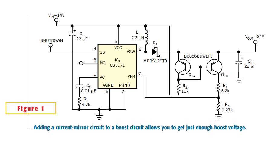
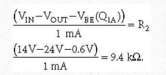
Adding a current-mirror circuit to a typical boost circuit allows you to select the amount of boost voltage and to ensure a constant difference between the input and the output voltages (Figure 1). This circuit is useful for high-side-drive applications, in which a simple voltage doubler is unacceptable because of the voltage range of the components involved or where the input voltage can vary widely. You can also use the circuit at the front end of a power supply to ensure that the PWM controller has enough voltage to start correctly in low-input-voltage conditions. The circuit maintains a 10V difference between VIN and VOUT, but you can easily change it to provide other voltages. The PWM circuit in Figure 1 is the CS5171 from On Semiconductor (www.onsemi.com), but you can use the idea with any boost circuit. The current-mirror circuit, comprising the dual-pnp transistor, Q1, and the associated resistors, establishes a current that depends on the voltage difference between VIN and VOUT. The dual-pnp transistor has a VCEO of 65V. In this case, VIN=14V (nominal), so you need VOUT to be 24V (nominal). First, calculate a value for R2, thus establishing the reference current. If you select a reference current of 1 mA, you obtain

Because the output voltage is not critical, you use a 10-kΩ resistor.
Q1B mirrors the current and sets up the feedback voltage to the PWM circuit. The CS5171 has an internal voltage of 1.28V (typical), so R3 yields the correct feedback voltage when the current flowing through it is 1 mA. In this case, by selecting 1.27 kΩ for R3, you obtain an output voltage of 24V. As VIN varies, VOUT tracks it and maintains a 10V difference between the input and the output. R4 helps reduce the power dissipation in Q1B.
标签:blog http io ar os sp for on 2014
原文地址:http://www.cnblogs.com/shangdawei/p/4128199.html