标签:des blog http io ar os sp for on
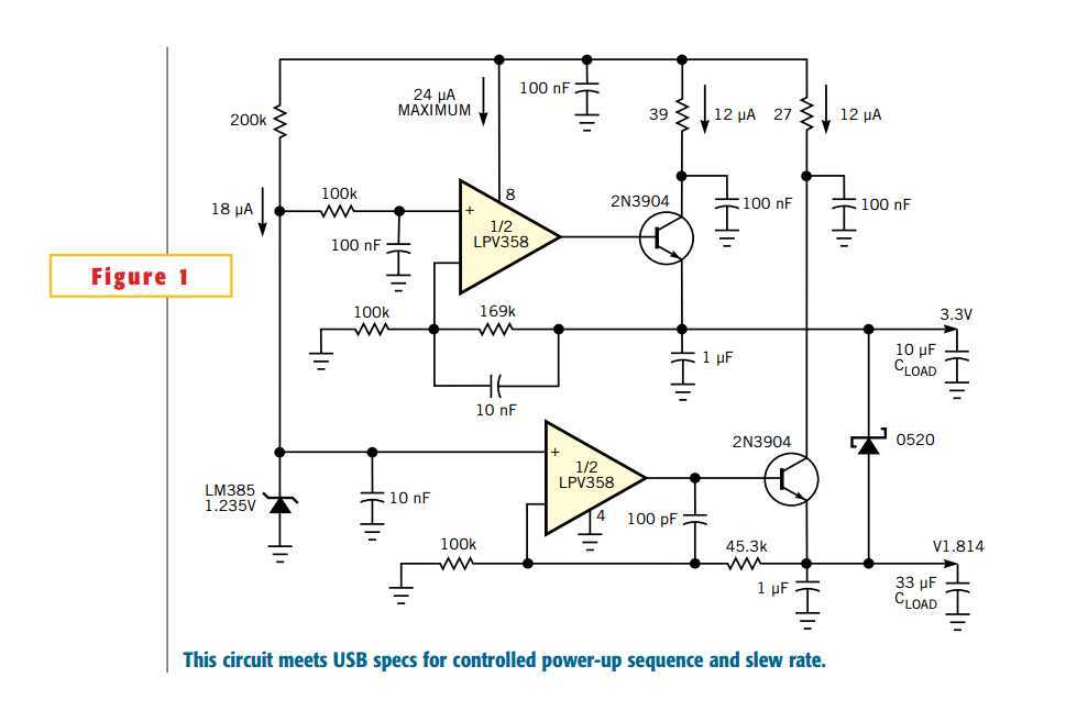
This Design Idea stems from the limited availability of IC voltage regulators that can meet key USB-power specs, coupled with the need for turn-on sequencing and rise-time control at each output. As always, for PC-related designs, minimum cost is a primary motivation. USB specs require all loads to limit inrush current to less than 100 mA plus 50 µC of charge when powered on. If permission is granted to increase the load to 500 mA, inrush limiting may be required again to prevent excursions over the 500-mA limit. The other troublesome USB-power requirement is the "suspend"-current maximum of 500 µA, of which you may use only 250 µA; a termination resistor requires the rest. Suspend requires the load to power down but keep alive just enough to listen for permission to power up again. So, the sum of the regulators‘ operating currents plus load current must be less than 250 µA. The dual-regulator circuit meets the USB spec and powers an ASIC that requires a core voltage of 1.8V and I/O voltage of 3.3V to rise with a controlled sequence and slew rate (Figure 1).

Specifically, the core and I/O voltages track within 0.5V until the core voltage reaches 1.8V. The controlled slew rate limits inrush current to less than 100 mA. Two micropower linear regulators use a very-low-power bandgap voltage reference and a dual op amp. The dual op amp must draw low power, have inputs active to ground, provide rail-to-rail drive, and not reverse polarity as you apply power. Each op amp has an npn transistor buffering its output to provide greater than 100 mA. The regulator loops are stable with these components and values. Simple current limiting accrues from a resistor in series with each 2N3904 collector lead.
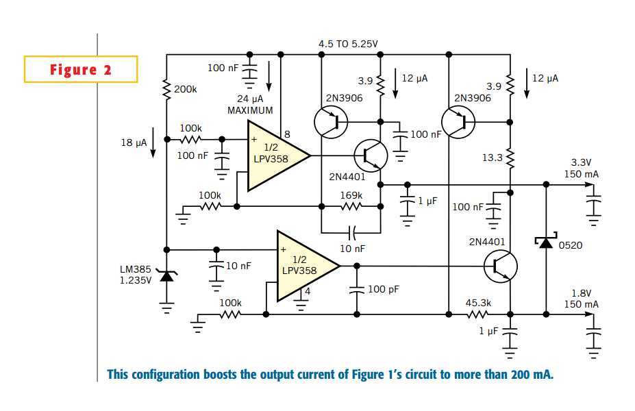
A 200-kΩ resistor that connects to the 10-nF bypass capacitor at the voltage reference controls the 1.8V power-up rise time. The resulting rise time is approximately tRISE=20 µA×1.235V/10 nF=2.5 msec. The 3.3V supply follows the 1.8V supply, according to the 10-msec time constant of its 100-kΩ, 100-nF input filter. A small Schottky diode connected between 1.8V and 3.3V guarantees the 3.3V to be within 0.5V of the 1.8V during start-up. Inrush current of approximately 38 mA is IINRUSH=CLOAD(dV/dt), where CLOAD is the total load capacitance, dV=1.8V, and dt=tRISE. The total operating quiescent current of this dual regulator measures just 56 µA, and the worst-case maximum spec for the circuit in Figure 1is 64 µA. This figure leaves 194 µA available for the load during suspend mode. Figure 1‘s application requires regulator current of less than 150 mA from each output. You can easily modify the circuit to provide more than 200 mA per channel by substituting a 2N4401 for the 2N- 3904 and adding active current limit with a 2N3906 (Figure 2).

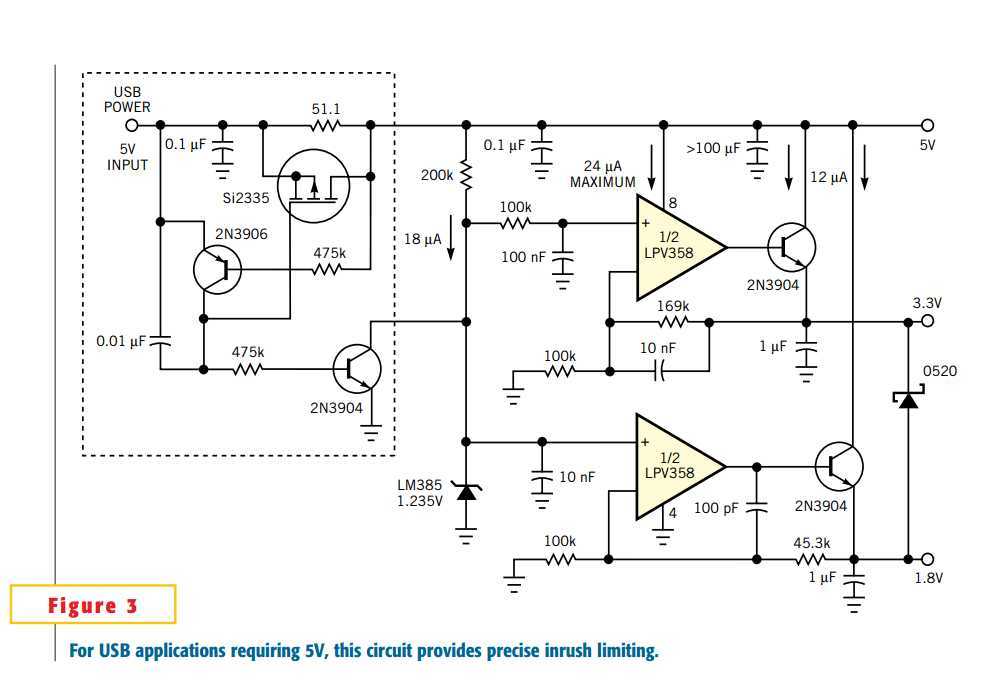
Many USB-powered supplies also require a 5V output.

The circuit of Figure 3 provides precise inrush limiting for 5V and a signal to enable other supplies or loads. The portion of the circuit in broken lines limits inrush current to less than 100 mA at power-on. The 51.1Ω resistor charges the 5V load capacitance to approximately 4.5V, and the 2N3906 then releases the PFET‘s gate, allowing it to short-circuit the resistor. Finally, the 2N3904 turns off, enabling the linear regulators to start. This inrush circuit precisely limits peak inrush current independently of capacitive load. Use of a large load capacitance prevents load-current spikes from reaching the USB input line.
Dual-voltage regulator meets USB-power needs
标签:des blog http io ar os sp for on
原文地址:http://www.cnblogs.com/shangdawei/p/4128214.html