标签:blog http io ar os 使用 sp on 数据
1.时钟发生器2.指令寄存器3.累加器4.RISC CPU算术逻辑运算单元5.数据控制器6.状态控制器7.程序计数器8.地址多路器9.外围模块10.地址译码器
a.RAMb.ROM

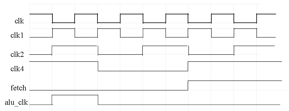
module clk_gen (clk,reset,clk1,clk2,clk4,fetch,alu_clk);
input clk,reset;
output clk1,clk2,clk4,fetch,alu_clk;
wire clk,reset;
reg clk2,clk4,fetch,alu_clk;
reg[7:0] state;
parameter S1 = 8‘b00000001,
	S2 = 8‘b00000010,
	S3 = 8‘b00000100,
	S4 = 8‘b00001000,
	S5 = 8‘b00010000,
	S6 = 8‘b00100000,
	S7 = 8‘b01000000,
	S8 = 8‘b10000000,
	idle = 8‘b00000000;
assign clk1 = ~clk;

always @(negedge clk)
	if(reset)
		begin
			clk2 <= 0;
			clk4 <= 1;
			fetch <= 0;
			alu_clk <= 0;
			state <= idle;
		end
	else
		begin
			case(state)
			S1:
				begin
					clk2 <= ~clk2;
					alu_clk <= ~alu_clk;
					state <= S2;
				end
			S2:
				begin
					clk2 <= ~clk2;
					clk4 <= ~clk4;
					alu_clk <= ~alu_clk;
					state <= S3;
				end
			S3:
				begin
					clk2 <= ~clk2;
					state <= S4;
				end
			S4:
				begin
					clk2 <= ~clk2;
					clk4 <= ~clk4;
					fetch <= ~fetch;
					state <= S5;
				end
			S5:
				begin
					clk2 <= ~clk2;
					state <= S6;
				end
			S6:
				begin
					clk2 <= ~clk2;
					clk4 <= ~clk4;
					state <= S7;
				end
			S7:
				begin
					clk2 <= ~clk2;
					state <= S8;
				end
			S8:
				begin
					clk2 <= ~clk2;
					clk4 <= ~clk4;
					fetch <= ~fetch;
					state <= S1;
				end
			idle: state <= S1;
			default: state <= idle;
		endcase
	end
endmodule
//--------------------------------------------------------------------------------
由于在时钟发生器的设计中采用了同步状态机的设计方法,不但使clk_gen模块的源程序可以被各种综合器综合,也使得由其生成的clk1、clk2、clk4、fetch、alu_clk 在跳变时间同步性能上有明显的提高,为整个系统的性能提高打下了良好的基础。
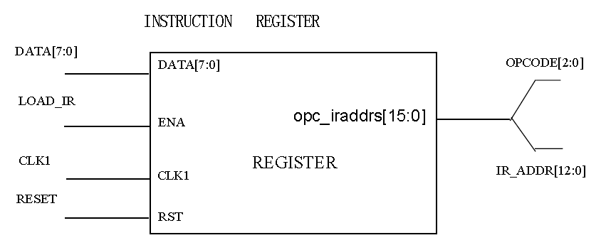
//---------------------------------------------------------------
module register(opc_iraddr,data,ena,clk1,rst);
output [15:0] opc_iraddr;
input [7:0] data;
input ena, clk1, rst;
reg [15:0] opc_iraddr;
reg state;

always @(posedge clk1)
begin
	if(rst)
		begin
			opc_iraddr<=16‘b0000_0000_0000_0000;
			state<=1‘b0;
		end
	else
		begin
			if(ena) //如果加载指令寄存器信号load_ir到来,
				begin //分两个时钟每次8位加载指令寄存器
					casex(state) //先高字节,后低字节
						1’b0: begin
							opc_iraddr[15:8]<=data;
							state<=1;
						end
						1’b1: begin
							opc_iraddr[7:0]<=data;
							state<=0;
						end
						default: begin
							opc_iraddr[15:0]<=16‘bxxxxxxxxxxxxxxxx;
							state<=1‘bx;
						end
					endcase
				end
			else
				state<=1‘b0;
		end
end
endmodule
//--------------------------------------------------------

//--------------------------------------------------------------
module accum( accum, data, ena, clk1, rst);
output[7:0]accum;
input[7:0]data;
input ena,clk1,rst;
reg[7:0]accum;

always@(posedge clk1)
	begin
		if(rst)
			accum<=8‘b0000_0000; //Reset
		else
			if(ena) //当CPU状态控制器发出load_acc信号
				accum<=data; //Accumulate
	end
endmodule
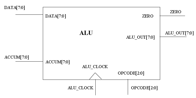
//------------------------------------------------------------------------------
module alu (alu_out, zero, data, accum, alu_clk, opcode);
output [7:0]alu_out;
output zero;
input [7:0] data, accum;
input [2:0] opcode;
input alu_clk;
reg [7:0] alu_out;

parameter HLT =3’b000,
	SKZ =3’b001,
	ADD =3’b010,
	ANDD =3’b011,
	XORR =3’b100,
	LDA =3’b101,
	STO =3’b110,
	JMP =3’b111;

assign zero = !accum;
always @(posedgealu_clk)
	begin //操作码来自指令寄存器的输出opc_iaddr<15..0>的低3位
		casex (opcode)
			HLT: alu_out<=accum;
			SKZ: alu_out<=accum;
			ADD: alu_out<=data+accum;
			ANDD: alu_out<=data&accum;
			XORR: alu_out<=data^accum;
			LDA: alu_out<=data;
			STO: alu_out<=accum;
			JMP: alu_out<=accum;
			default: alu_out<=8‘bxxxx_xxxx;
		endcase
	end
endmodule
//----------------------------------------------------------------------------

//--------------------------------------------------------------------
module datactl (data,in,data_ena);
output [7:0]data;
input [7:0]in;
input data_ena;

assign data = (data_ena)? In : 8‘bzzzz_zzzz;

endmodule
//--------------------------------------------------------------------

//------------------------------------------------------------------------------
module adr(addr,fetch,ir_addr,pc_addr);
output [12:0] addr;
input [12:0] ir_addr, pc_addr;
input fetch;


assign addr = fetch? pc_addr : ir_addr;


endmodule
//------------------------------------------------------------------------------
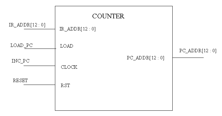
//------------------------------------------------------------------------------
module counter ( pc_addr, ir_addr, load, clock, rst);
output [12:0] pc_addr;
input [12:0] ir_addr;
input load, clock, rst;
reg [12:0] pc_addr;

always @( posedge clock or posedge rst )
	begin
		if(rst)
			pc_addr<=13‘b0_0000_0000_0000;
		else
			if(load)
				pc_addr<=ir_addr;
			else
				pc_addr <= pc_addr + 1;
	end
endmodule
//------------------------------------------------------------------------------

//------------------------------------------------------------------------------
module machinectl( ena, fetch, rst);
output ena;
input fetch, rst;
reg ena;
always @(posedge fetch or posedge rst)


begin
	if(rst)
		ena<=0;
	else
		ena<=1;
end
endmodule
//------------------------------------------------------------------------------
状态机是CPU的控制核心,用于产生一系列的控制信号,启动或停止某些部件。CPU何时进行读指令读写I/O端口,RAM区等操作,都是由状态机来控制的。状态机的当前状态,由变量state记录,state的值就是当前这个指令周期中已经过的时钟数(从零计起)。
//------------------------------------------------------------------------------
module machine( inc_pc, load_acc, load_pc, rd,wr, load_ir,
datactl_ena, halt, clk1, zero, ena, opcode );
output inc_pc, load_acc, load_pc, rd, wr, load_ir;
output datactl_ena, halt;
input clk1, zero, ena;
input [2:0] opcode;
reg inc_pc, load_acc, load_pc, rd, wr, load_ir;
reg datactl_ena, halt;
reg [2:0] state;

parameter HLT = 3 ‘b000,
	SKZ = 3 ‘b001,
	ADD = 3 ‘b010,
	ANDD = 3 ‘b011,
	XORR = 3 ‘b100,
	LDA = 3 ‘b101,
	STO = 3 ‘b110,
	JMP = 3 ‘b111;

always @( negedge clk1 )
	begin
		if ( !ena ) //接收到复位信号RST,进行复位操作
			begin
				state<=3‘b000;
				{inc_pc,load_acc,load_pc,rd}<=4‘b0000;
				{wr,load_ir,datactl_ena,halt}<=4‘b0000;
			end
		else
			ctl_cycle;
	end
//-----------------begin of task ctl_cycle---------
task ctl_cycle;
begin
	casex(state)
		3’b000: //load high 8bits in struction
			begin
				{inc_pc,load_acc,load_pc,rd}<=4‘b0001;
				{wr,load_ir,datactl_ena,halt}<=4‘b0100;
				state<=3’b001;
			end
		3’b001: //pc increased by one then load low 8bits instruction
			begin
				{inc_pc,load_acc,load_pc,rd}<=4‘b1001;
				{wr,load_ir,datactl_ena,halt}<=4‘b0100;
				state<=3’b010;
			end
		3’b010: //idle
			begin
				{inc_pc,load_acc,load_pc,rd}<=4‘b0000;
				{wr,load_ir,datactl_ena,halt}<=4‘b0000;
				state<=3’b011;
			end
		3’b011: //next instruction address setup 分析指令从这里开始
			begin
				if(opcode==HLT) //指令为暂停HLT
					begin
						{inc_pc,load_acc,load_pc,rd}<=4‘b1000;
						{wr,load_ir,datactl_ena,halt}<=4‘b0001;
					end
				else
					begin
						{inc_pc,load_acc,load_pc,rd}<=4‘b1000;
						{wr,load_ir,datactl_ena,halt}<=4‘b0000;
					end
				state<=3’b100;
			end
		3’b100: //fetch oprand
			begin
				if(opcode==JMP)
					begin
						{inc_pc,load_acc,load_pc,rd}<=4‘b0010;
						{wr,load_ir,datactl_ena,halt}<=4‘b0000;
					end
				else
				if( opcode==ADD || opcode==ANDD ||
					opcode==XORR || opcode==LDA)
						begin
							{inc_pc,load_acc,load_pc,rd}<=4‘b0001;
							{wr,load_ir,datactl_ena,halt}<=4‘b0000;
						end
				else
					if(opcode==STO)
						begin
							{inc_pc,load_acc,load_pc,rd}<=4‘b0000;
							{wr,load_ir,datactl_ena,halt}<=4‘b0010;
						end
				else
					begin
						{inc_pc,load_acc,load_pc,rd}<=4‘b0000;
						{wr,load_ir,datactl_ena,halt}<=4‘b0000;
				end
				state<=3’b101;
			end
		3’b101: //operation
			begin
				if ( opcode==ADD||opcode==ANDD||opcode==XORR||opcode==LDA )
					begin //过一个时钟后与累加器的内容进行运算
						{inc_pc,load_acc,load_pc,rd}<=4‘b0101;
						{wr,load_ir,datactl_ena,halt}<=4‘b0000;
					end
				else
					if( opcode==SKZ && zero==1)
						begin
							{inc_pc,load_acc,load_pc,rd}<=4‘b1000;
							{wr,load_ir,datactl_ena,halt}<=4‘b0000;
						end
				else
					if(opcode==JMP)
						begin
							{inc_pc,load_acc,load_pc,rd}<=4‘b1010;
							{wr,load_ir,datactl_ena,halt}<=4‘b0000;
						end
				else
					if(opcode==STO)
						begin
							//过一个时钟后把wr变1就可写到RAM中
							{inc_pc,load_acc,load_pc,rd}<=4‘b0000;
							{wr,load_ir,datactl_ena,halt}<=4‘b1010;
						end
				else
					begin
						{inc_pc,load_acc,load_pc,rd}<=4‘b0000;
						{wr,load_ir,datactl_ena,halt}<=4‘b0000;
					end
				state<=3’b110;
			end
	3’b110: //idle
		begin
			if ( opcode==STO )
				begin
					{inc_pc,load_acc,load_pc,rd}<=4‘b0000;
					{wr,load_ir,datactl_ena,halt}<=4‘b0010;
				end
			else
				if ( opcode==ADD||opcode==ANDD||opcode==XORR||opcode==LDA)
					begin
						{inc_pc,load_acc,load_pc,rd}<=4‘b0001;
						{wr,load_ir,datactl_ena,halt}<=4‘b0000;
					end
			else
				begin
					{inc_pc,load_acc,load_pc,rd}<=4‘b0000;
					{wr,load_ir,datactl_ena,halt}<=4‘b0000;
				end
		state<=3’b111;
		end
	3’b111: //
		begin
			if( opcode==SKZ && zero==1 )
				begin
					{inc_pc,load_acc,load_pc,rd}<=4‘b1000;
					{wr,load_ir,datactl_ena,halt}<=4‘b0000;
				end
			else
				begin
					{inc_pc,load_acc,load_pc,rd}<=4‘b0000;
					{wr,load_ir,datactl_ena,halt}<=4‘b0000;
				end
			state<=3’b000;
		end
	default:
		begin
			{inc_pc,load_acc,load_pc,rd}<=4‘b0000;
			{wr,load_ir,datactl_ena,halt}<=4‘b0000;
			state<=3’b000;
		end
	endcase
end
endtask
//-----------------end of task ctl_cycle---------
endmodule
//------------------------------------------------------------------------------
module addr_decode( addr, rom_sel, ram_sel);
output rom_sel, ram_sel;
input [12:0] addr;
reg rom_sel, ram_sel;
always @( addr )

begin
	casex(addr)
		13‘b1_1xxx_xxxx_xxxx:{rom_sel,ram_sel}<=2‘b01;
		13‘b0_xxxx_xxxx_xxxx:{rom_sel,ram_sel}<=2‘b10;
		13‘b1_0xxx_xxxx_xxxx:{rom_sel,ram_sel}<=2‘b10;
		default:{rom_sel,ram_sel}<=2‘b00;
	endcase
end
endmodule
地址译码器用于产生选通信号,选通ROM或RAM。 module ram( data, addr, ena, read, write ); inout [7:0] data; input [9:0] addr; input ena; input read, write; reg [7:0] ram [10‘h3ff:0]; assign data = ( read && ena )? ram[addr] : 8‘hzz; always @(posedge write) begin ram[addr]<=data; end endmodule
module rom( data, addr, read, ena );
output [7:0] data;
input [12:0] addr;
input read, ena;
reg [7:0] memory [13‘h1fff:0];
wire [7:0] data;

assign data= ( read && ena )? memory[addr] : 8‘bzzzzzzzz;

endmodule
ROM用于装载测试程序,可读不可写。RAM用于存放数据,可读可写。


标签:blog http io ar os 使用 sp on 数据
原文地址:http://www.cnblogs.com/Karma-wjc/p/4132184.html