标签:
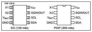
DS1307是Maxim的串行、I2C实时时钟芯片。主要特性有:

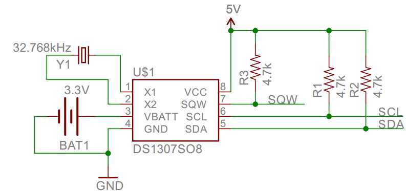
采用I2C接口与Arduino连接。SQW/OUT脚亦为开漏(open-drain)设计,需要接上拉电阻。

DS1307的VCC脚接Arduino UNO的5V;GND脚接Arduino UNO的GND;SDA脚接Arduino UNO的A4(SDA);SCL脚接Arduino UNO的A5(SCL)。
1. 写寄存器时,先写入寄存器指针(Register pointer),之后依次写入寄存器内容。每写入一个字节,Register pointer都自动加一。
2. 读寄存器时,也是先写入Register pointer,之后发Sr(Repeated start),依次读出寄存器内容。同样的,每读出一个字节,Register pinter都自动加一。
1. 首先设置DS1307时间。代码中timeDec数组保存的是当前时间,根据实际调整。

 1 /*
 2 real time clock using DS1307
 3 function: set the time
 4 */
 5
 6 #include <Wire.h>
 7
 8 #define ADDRESS_DS1307 0x68
 9
10 byte timeDec[] = {15, 1, 15, 5, 19, 20, 0};
11 byte timeBcd[] = {0, 0, 0, 0, 0, 0, 0};
12 //time = {year, month, date, day, hours, minutes, seconds};
13
14 void setup()
15 {
16     Wire.begin();
17     Serial.begin(9600);
18
19     //convert decimal to BCD code
20     int i;
21     for (i = 0; i < 7; i++)
22     {
23         timeBcd[i] = DecToBcd(timeDec[i]);
24     }
25
26     //set the time
27     Wire.beginTransmission(ADDRESS_DS1307);
28     Wire.write(0x00);
29     for (i = 0; i < 7; i++)
30     {
31         Wire.write(timeBcd[6-i]);
32     }
33     Wire.endTransmission();
34
35     Serial.println("Time has been set.");
36
37 }
38
39 void loop()
40 {
41     delay(4000);
42 }
43
44 // Convert normal decimal numbers to binary coded decimal
45 byte DecToBcd(byte val)
46 {
47     byte res;
48     if ((val <= 99) && (val >= 0))
49     {
50         res = ((val/10)<<4) | (val%10);
51     }
52     else
53     {
54         res = 0;
55         Serial.println("Error");
56     }
57     return res;
58 }
59 // Convert binary coded decimal to normal decimal numbers
60 byte BcdToDec(byte val)
61 {
62     byte res;
63     if (val <= 0x99)
64     {
65         res = (val >> 4)*10 + (val & 0x0F);
66     }
67     else
68     {
69         res = 0;
70         Serial.println("Error");
71     }
72     return res;
73 }
2. 之后可以向DS1307获取实时时间。

 1 /*
 2 real time clock using DS1307
 3 function: read the time
 4 */
 5
 6 #include <Wire.h>
 7
 8 #define ADDRESS_DS1307 0x68
 9
10 byte timeBcd[] = {0, 0, 0, 0, 0, 0, 0};
11 //time = {year, month, date, day, hours, minutes, seconds};
12
13 void setup()
14 {
15     Wire.begin();
16     Serial.begin(9600);
17 }
18
19 void loop()
20 {
21     //read the time
22     Wire.beginTransmission(ADDRESS_DS1307);
23     Wire.write(0x00);
24     Wire.endTransmission();
25     Wire.requestFrom(ADDRESS_DS1307, 7);
26     if (Wire.available() >= 7)
27     {
28         for (int i = 0; i < 7; i++)
29         {
30             timeBcd[6-i] = Wire.read();
31         }
32     }
33
34     //print
35     Serial.print("20"); Serial.print(timeBcd[0], HEX); Serial.print("/");
36     Serial.print(timeBcd[1], HEX); Serial.print("/"); Serial.print(timeBcd[2], HEX);
37     Serial.print(" "); Serial.print(BcdToDay(timeBcd[3])); Serial.print(" ");
38     Serial.print(timeBcd[4], HEX); Serial.print(":");
39     Serial.print(timeBcd[5], HEX); Serial.print(":");
40     Serial.print(timeBcd[6], HEX); Serial.println();
41
42     delay(1000);
43 }
44
45
46 // Convert binary coded decimal to day
47 String BcdToDay(byte val)
48 {
49     String res;
50     switch(val)
51     {
52         case 1: res = "Sunday"; break;
53         case 2: res = "Monday"; break;
54         case 3: res = "Tuesday"; break;
55         case 4: res = "Wednesday"; break;
56         case 5: res = "Thursday"; break;
57         case 6: res = "Friday"; break;
58         case 7: res = "Saturday"; break;
59         default: res = "Error!";
60     }
61     return res;
62 }
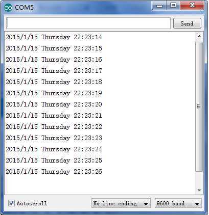
程序运行后,通过串口打印当前时间如下图。

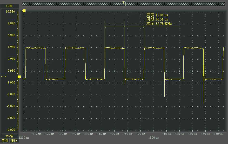
3. 通过设置控制寄存器,可以设置SQW/OUT管脚输出高电平、低电平或某个频率的方波。方波支持的频率有1Hz、4.096kHz、8.192kHz、32.768kHz。以下代码设置的频率为32.768kHz。

 1 /*
 2 real time clock using DS1307
 3 function: output the square-wave
 4 */
 5
 6 #include <Wire.h>
 7
 8 #define ADDRESS_DS1307 0x68
 9 #define CONTROL_REGISTER 0x07
10
11 void setup()
12 {
13     Wire.begin();
14     Serial.begin(9600);
15
16     //set the time
17     Wire.beginTransmission(ADDRESS_DS1307);
18     Wire.write(CONTROL_REGISTER);
19     Wire.write(0b00010011); //frequency = 32.768kHz
20     Wire.endTransmission();
21
22     Serial.println("Square-wave output is enabled.");
23 }
24
25 void loop()
26 {
27     delay(4000);
28 }
与示波器测试的信号图形相符。

Maxim - DS1307 64x8、串行、I²C实时时钟
Tutorial – Using DS1307 and DS3231 Real-time Clock Modules with Arduino
Digital Clock with Arduino and DS1307
Assemble an Adafruit DS1307 Real Time Clock Kit
标签:
原文地址:http://www.cnblogs.com/zlbg/p/4227428.html