标签:
1、为了更好的方便调试,串口必须要有的,主要打印一些信息,当前时钟、转换后的电压值和I2C读出的数据。
2、通过GPIO 模拟I2C对镁光的MT9V024进行参数初始化。之前用我以前公司SP0A19芯片,是I2C是8位宽的,而镁光的地址是8位,而数据位是16个字节,
其实不管是8位还是16位,每次发送都是8个字节然后一个应答位,所以只要稍微改下代码即可。
3、实现两路ADC连续转换,两路ADC转换:一路是检测锂电池电压;一路是检测压力传感器,其实都是检测电压,当检测到压力为零,并累计多长时间后进入停止模式,在进入停止模式后,再次通过压力挤压唤醒单片机,从而退出停止模式,进入正常工作状态。
4、中断,唤醒后会进入中断EXTI9_5_IRQHandler()函数,对ADC转换在一次进行配置;串口接收中断void USART2_IRQHandler(void)数据处理,串口接收数据,并通过I2C给Sensor进行配置,从而实现在线调试Camera Sensor,就不需在代码中改参数进行编译再下载。
5、代码实现:
1)、USART
.h

1 #ifndef __USART_H
2 #define __USART_H
3
4 #include "stm32f2xx_gpio.h"
5 #include <stdio.h>
6
7 void USART_Config(void);
8
9 #endif
.c
 1 #include "USART.h"
 2 #ifdef __GNUC__
 3   /* With GCC/RAISONANCE, small printf (option LD Linker->Libraries->Small printf
 4      set to ‘Yes‘) calls __io_putchar() */
 5   #define PUTCHAR_PROTOTYPE int __io_putchar(int ch)
 6 #else
 7   #define PUTCHAR_PROTOTYPE int fputc(int ch, FILE *f)
 8 #endif /* __GNUC__ */
 9
10 void USART_Config(void)
11 {
12     GPIO_InitTypeDef GPIO_InitSturct;
13     USART_InitTypeDef USART_InitSturct;
14
15     RCC_AHB1PeriphClockCmd(RCC_AHB1Periph_GPIOA,ENABLE);
16     RCC_APB1PeriphClockCmd(RCC_APB1Periph_USART2,ENABLE);
17
18     GPIO_PinAFConfig(GPIOA,GPIO_PinSource2,GPIO_AF_USART2);
19     GPIO_PinAFConfig(GPIOA,GPIO_PinSource3,GPIO_AF_USART2);
20
21     //TX
22     GPIO_InitSturct.GPIO_Pin = GPIO_Pin_2;
23     GPIO_InitSturct.GPIO_OType = GPIO_OType_PP;//推挽输出
24     GPIO_InitSturct.GPIO_Mode = GPIO_Mode_AF; //复用模式
25     GPIO_InitSturct.GPIO_Speed = GPIO_Speed_50MHz;
26     GPIO_InitSturct.GPIO_PuPd = GPIO_PuPd_UP;//上拉
27
28     GPIO_Init(GPIOA,&GPIO_InitSturct);
29
30     //RX
31     GPIO_InitSturct.GPIO_Pin = GPIO_Pin_3;
32     GPIO_InitSturct.GPIO_Mode = GPIO_Mode_AF;//复用模式
33     GPIO_InitSturct.GPIO_OType = GPIO_OType_OD;
34     GPIO_InitSturct.GPIO_PuPd = GPIO_PuPd_UP;
35
36     GPIO_Init(GPIOA,&GPIO_InitSturct);
37
38     USART_InitSturct.USART_BaudRate = 115200;//波特率设置
39     USART_InitSturct.USART_WordLength = USART_WordLength_8b;//发送的字节长度为8位
40     USART_InitSturct.USART_StopBits = USART_StopBits_1;//停止位 1位
41     USART_InitSturct.USART_Parity = USART_Parity_No;  //无奇偶位
42     USART_InitSturct.USART_HardwareFlowControl = USART_HardwareFlowControl_None; //选择不是硬件控制流
43     USART_InitSturct.USART_Mode = USART_Mode_Rx | USART_Mode_Tx; //发送接收使能
44
45     USART_Init(USART2,&USART_InitSturct);//进行初始化
46     USART_ITConfig(USART2, USART_IT_RXNE, ENABLE);//开启接收中断
47     USART_Cmd(USART2,ENABLE);//启动串口
48 }
49
50
51 /**
52   * @brief  Retargets the C library printf function to the USART1.
53   * @param  None
54   * @retval None
55   */
56 PUTCHAR_PROTOTYPE
57 {
58   /* Place your implementation of fputc here */
59   /* e.g. write a character to the USART */
60   USART_SendData(USART2, (uint8_t) ch);
61
62   /* Loop until the end of transmission */
63   while (USART_GetFlagStatus(USART2, USART_FLAG_TC) == RESET)
64   {}
65
66   return ch;
67 }
2)、I2C
.h
 1 #ifndef __I2C_H
 2 #define __I2C_H
 3
 4 #include "stm32f2xx_i2c.h"
 5 #include "stm32f2xx_gpio.h"
 6
 7 typedef unsigned   char uint8_t;
 8
 9 #define TRUE 1
10 #define FALSE 0
11
12 void GPIO_I2C_Config(void);
13 static void I2C_delay(uint16_t cnt);
14 uint8_t I2C_Start(void);
15 void I2C_Stop(void);
16 void I2C_Ack(void);
17 void I2C_NoAck(void);
18 uint8_t I2C_WaitAck(void) ;
19 void I2C_SendByte(uint8_t SendByte);
20 uint8_t I2C_ReceiveByte(void);
21 uint8_t Write_One_Byte(uint8_t addr, uint16_t thedata, uint8_t bit_width);
22 uint16_t Read_One_Byte(uint8_t addr);
23
24
25 #endif
.c
  1 #include "I2C.h"
  2
  3 //DELAY_TIME = 50  5us
  4 //DELAY_TIME = 100 10us
  5 #define        T_Cycle                                            200
  6 #define T_1QuarterCycle                                T_Cycle/4  //t = 1/4T, scl T = 10us  f=100k
  7 #define T_HalfCycle                                        T_Cycle/2
  8
  9
 10 #define     SLAVE_ADDRESS_WRITE                    0x90            //0x42
 11 #define     SLAVE_ADDRESS_READ                     SLAVE_ADDRESS_WRITE | 0x01
 12 #define     SDA                                                  GPIO_Pin_11
 13 #define     SCL                                                  GPIO_Pin_10
 14 #define   GPIO_SCL                                        GPIOB
 15 #define   GPIO_SDA                                        GPIOB
 16 #define     RCC_AHB1Periph_GPIO_SDA            RCC_AHB1Periph_GPIOB
 17 #define     RCC_AHB1Periph_GPIO_SCL            RCC_AHB1Periph_GPIOB
 18
 19 #define     SCL_H         GPIOB->BSRRL     =     GPIO_Pin_10
 20 #define     SCL_L         GPIOB->BSRRH  =     GPIO_Pin_10
 21
 22 #define     SDA_H         GPIOB->BSRRL     =     GPIO_Pin_11
 23 #define     SDA_L         GPIOB->BSRRH  =     GPIO_Pin_11
 24
 25 #define     SCL_read      GPIOB->IDR      &     GPIO_Pin_10
 26 #define     SDA_read      GPIOB->IDR      &     GPIO_Pin_11
 27
 28 void GPIO_I2C_Config(void)
 29 {
 30     GPIO_InitTypeDef  GPIO_InitStructure;
 31
 32     RCC_AHB1PeriphClockCmd(RCC_AHB1Periph_GPIO_SDA,ENABLE);
 33     RCC_AHB1PeriphClockCmd(RCC_AHB1Periph_GPIO_SCL,ENABLE);
 34
 35     GPIO_InitStructure.GPIO_Pin = SDA; //sda
 36     GPIO_InitStructure.GPIO_Mode = GPIO_Mode_OUT;  //输出模式
 37     GPIO_InitStructure.GPIO_OType = GPIO_OType_OD;  //OD门
 38     GPIO_InitStructure.GPIO_PuPd = GPIO_PuPd_NOPULL; //浮空
 39     GPIO_InitStructure.GPIO_Speed = GPIO_Speed_50MHz;
 40     GPIO_Init(GPIO_SDA,&GPIO_InitStructure);
 41
 42     GPIO_InitStructure.GPIO_Pin = SCL; //scl
 43     GPIO_InitStructure.GPIO_Mode = GPIO_Mode_OUT;  //输出模式
 44     GPIO_InitStructure.GPIO_OType = GPIO_OType_OD;  //OD门
 45     GPIO_InitStructure.GPIO_PuPd = GPIO_PuPd_NOPULL; //浮空
 46     GPIO_InitStructure.GPIO_Speed = GPIO_Speed_50MHz;
 47     GPIO_Init(GPIO_SCL,&GPIO_InitStructure);
 48 }
 49
 50 void I2C_delay(uint16_t cnt)
 51 {
 52     while(cnt!=0)
 53        cnt--;
 54 }
 55
 56 uint8_t I2C_Start(void)
 57 {
 58     SDA_H;
 59     SCL_H;
 60     I2C_delay(T_1QuarterCycle);
 61     if(!SDA_read)return FALSE;
 62     SDA_L;
 63     I2C_delay(T_1QuarterCycle);
 64     if(SDA_read) return FALSE;
 65     SDA_L;
 66     I2C_delay(T_1QuarterCycle);
 67
 68     return TRUE;
 69 }
 70
 71 void I2C_Stop(void)
 72 {
 73     SCL_L;
 74     I2C_delay(T_1QuarterCycle);
 75     SDA_L;
 76     I2C_delay(T_1QuarterCycle);
 77     SCL_H;
 78     I2C_delay(T_1QuarterCycle);
 79     SDA_H;
 80     I2C_delay(T_1QuarterCycle);
 81 }
 82
 83 void I2C_Ack(void)
 84 {
 85     SCL_L;
 86     I2C_delay(T_1QuarterCycle);
 87     SDA_L;
 88     I2C_delay(T_1QuarterCycle);
 89     SCL_H;
 90     I2C_delay(T_1QuarterCycle);
 91     SCL_L;
 92     I2C_delay(T_1QuarterCycle);
 93 }
 94
 95 void I2C_NoAck(void)
 96 {
 97     SCL_L;
 98     I2C_delay(T_1QuarterCycle);
 99     SDA_H;
100     I2C_delay(T_1QuarterCycle);
101     SCL_H;
102     I2C_delay(T_1QuarterCycle);
103     SCL_L;
104     I2C_delay(T_1QuarterCycle);
105 }
106
107 uint8_t I2C_WaitAck(void)
108 {
109     SCL_L;
110     I2C_delay(T_1QuarterCycle);
111     SDA_H;        //SDA要拉高,以便读
112     I2C_delay(T_1QuarterCycle);
113     SCL_H;
114     I2C_delay(T_1QuarterCycle);
115     if(SDA_read)
116     {
117         SCL_L;
118         return FALSE;
119     }
120     I2C_delay(T_1QuarterCycle);
121     SCL_L;   //这个地方不能去掉
122
123     return TRUE;
124 }
125
126 void I2C_SendByte(uint8_t SendByte)
127 {
128     uint8_t i=8;
129     while(i--)
130     {
131         SCL_L;
132         I2C_delay(T_1QuarterCycle);
133         if(SendByte&0x80)//在SCL为低时,改变SDA上的数据
134             SDA_H;
135         else
136             SDA_L;
137         SendByte<<=1;
138         I2C_delay(T_1QuarterCycle);
139         SCL_H;
140         I2C_delay(T_HalfCycle);
141     }
142
143 }
144
145 uint8_t I2C_ReceiveByte(void)
146 {
147     uint8_t i=8;
148     uint8_t ReceiveByte=0;
149
150     SDA_H;  //上拉以便读数据
151     while(i--)
152     {
153         ReceiveByte<<=1;
154         SCL_L;
155         I2C_delay(T_1QuarterCycle);
156         SCL_H;
157         I2C_delay(T_1QuarterCycle);
158         if(SDA_read)
159         {
160             ReceiveByte|=0x01;
161         }
162         I2C_delay(T_1QuarterCycle);
163     }
164
165     return ReceiveByte;
166 }
167
168 uint8_t Write_One_Byte(uint8_t addr, uint16_t thedata, uint8_t bit_width)
169 {
170     uint8_t data_8bit_H = 0x00;
171     uint8_t data_8bit_L = 0x00;
172     if(bit_width == 8)     //把数据进行分开,位宽都是8
173     {
174             data_8bit_L = thedata;
175     }
176     else if(bit_width == 16)
177     {
178             data_8bit_H = (thedata & 0xff00) >>8;
179             data_8bit_L = thedata & 0x00ff;
180     }
181     else
182         return FALSE;
183
184     if (!I2C_Start()) return FALSE;
185     I2C_SendByte(SLAVE_ADDRESS_WRITE);
186     if (!I2C_WaitAck())
187     {
188         I2C_Stop();
189         return FALSE;
190     }
191     I2C_SendByte(addr);
192     I2C_WaitAck();
193
194     if(bit_width == 8)
195     {
196         I2C_SendByte(data_8bit_L);
197         I2C_WaitAck();
198     }
199     else
200     {
201         I2C_SendByte(data_8bit_H);
202         I2C_WaitAck();
203         I2C_SendByte(data_8bit_L);
204         I2C_WaitAck();
205     }
206
207     I2C_Stop();
208
209     return TRUE;
210 }
211
212 uint16_t Read_One_Byte(uint8_t addr)
213 {
214     uint16_t thedata = 0x0000;
215     if (!I2C_Start()) return FALSE;
216     I2C_SendByte(SLAVE_ADDRESS_WRITE);
217     if (!I2C_WaitAck())
218     {
219         I2C_Stop();
220         return FALSE;
221     }
222     I2C_SendByte(addr);
223     I2C_WaitAck();
224     I2C_Start();
225     I2C_SendByte(SLAVE_ADDRESS_READ);
226     I2C_WaitAck();
227
228     thedata = I2C_ReceiveByte();
229     thedata = thedata<<8;
230     I2C_Ack();
231     thedata |= I2C_ReceiveByte();
232     I2C_NoAck();
233     I2C_Stop();
234
235     return thedata;
236 }
3)、DMA
.h
 1 #ifndef __DMA_H
 2 #define __DMA_H
 3
 4 #include "stm32f2xx_dma.h"
 5
 6
 7
 8 void DMA_Config(void);
 9
10 #endif
.c
 1 #include "DMA.h"
 2
 3 #define N 2
 4 extern  vu16 ADC_ConvertedValue[N];
 5
 6 //#define PERIPH_BASE        ((uint32_t)0x40000000)
 7 //#define APB2PERIPH_BASE    (PERIPH_BASE + 0x00010000)
 8 //#define ADC1_BASE          (APB2PERIPH_BASE + 0x2000)
 9 //#define ADC1_DR_Address    (ADC1_BASE+0x4c)
10
11 #define ADC1_DR_Address    ((u32)0x4001204C)
12
13
14 void DMA_Config(void)
15 {
16     DMA_InitTypeDef DMA_InitStructure;
17
18     RCC_AHB1PeriphClockCmd(RCC_AHB1Periph_DMA2,ENABLE);//使能DMA2时钟,ADC1是挂在DMA2上
19
20     DMA_DeInit(DMA2_Stream0);
21     DMA_InitStructure.DMA_Channel = DMA_Channel_0; //指定数据通 这里不能随便改成 DMA_Channel_1/2,得看手册DMA2 request mapping
22     DMA_InitStructure.DMA_PeripheralBaseAddr = (uint32_t)ADC1_DR_Address; //指定外设接口地址
23   DMA_InitStructure.DMA_Memory0BaseAddr = (uint32_t)&ADC_ConvertedValue; //指定寄存器变量,转换后的数据就存放在这里
24   DMA_InitStructure.DMA_DIR = DMA_DIR_PeripheralToMemory;//指定外设到memory
25   DMA_InitStructure.DMA_BufferSize = 2; //指定Buff大小
26   DMA_InitStructure.DMA_PeripheralInc = DMA_PeripheralInc_Disable;//指定外设增量,外设地址不变
27   DMA_InitStructure.DMA_MemoryInc = DMA_MemoryInc_Enable;//指定memory增量,递增
28   DMA_InitStructure.DMA_PeripheralDataSize = DMA_PeripheralDataSize_HalfWord;
29                                    //ADC分辨率设置的是12bit,若这改为DMA_PeripheralDataSize_Byte就出错,会丢失一些数据
30   DMA_InitStructure.DMA_MemoryDataSize = DMA_MemoryDataSize_HalfWord;
31   DMA_InitStructure.DMA_Mode = DMA_Mode_Circular;//循环传输
32   DMA_InitStructure.DMA_Priority = DMA_Priority_High;
33   DMA_InitStructure.DMA_FIFOMode = DMA_FIFOMode_Disable;//是直接模式还是FIFO模式
34   DMA_InitStructure.DMA_FIFOThreshold = DMA_FIFOThreshold_HalfFull;
35   DMA_InitStructure.DMA_MemoryBurst = DMA_MemoryBurst_Single;
36   DMA_InitStructure.DMA_PeripheralBurst = DMA_PeripheralBurst_Single;
37
38   DMA_Init(DMA2_Stream0, &DMA_InitStructure);//DMA2初始化
39 //DMA_ITConfig(DMA2_Stream0, DMA_IT_TC, ENABLE);//开DMA中断
40   DMA_Cmd(DMA2_Stream0, ENABLE);//DMA2使能
41
42 }
4)、ADC
.h
 1 #ifndef __ADC_H
 2 #define __ADC_H
 3
 4 #include "stm32f2xx_adc.h"
 5 #include "stm32f2xx_gpio.h"
 6
 7
 8 void ADC_Config(void);
 9
10 #endif
.c
 1 #include "adc.h"
 2
 3 void ADC_Config(void)
 4 {
 5     GPIO_InitTypeDef             GPIO_InitStructure;
 6     ADC_InitTypeDef       ADC_InitStructure;
 7   ADC_CommonInitTypeDef ADC_CommonInitStructure;
 8
 9     RCC_AHB1PeriphClockCmd(RCC_AHB1Periph_GPIOA, ENABLE);//使能GPIO接口时钟
10     RCC_APB2PeriphClockCmd(RCC_APB2Periph_ADC1, ENABLE);//使能ADC复用接口
11
12     /* Configure ADC1 Channel PA6 adn PA7 pin as analog input ******************************/
13     GPIO_InitStructure.GPIO_Pin = GPIO_Pin_6 | GPIO_Pin_7;
14   GPIO_InitStructure.GPIO_Mode = GPIO_Mode_AN;
15   GPIO_InitStructure.GPIO_PuPd = GPIO_PuPd_NOPULL ;
16 //GPIO_InitStructure.GPIO_Speed = GPIO_Speed_50MHz;//输入时不需设置速率
17   GPIO_Init(GPIOA, &GPIO_InitStructure);
18
19     /* ADC Common Init **********************************************************/
20   ADC_CommonInitStructure.ADC_Mode = ADC_Mode_Independent;
21   ADC_CommonInitStructure.ADC_Prescaler = ADC_Prescaler_Div4;//60M/4=15M  max value is 30MHz
22   ADC_CommonInitStructure.ADC_DMAAccessMode = ADC_DMAAccessMode_Disabled;
23   ADC_CommonInitStructure.ADC_TwoSamplingDelay = ADC_TwoSamplingDelay_5Cycles;
24   ADC_CommonInit(&ADC_CommonInitStructure);
25
26     /* ADC1 Init ****************************************************************/
27   ADC_InitStructure.ADC_Resolution = ADC_Resolution_12b; //12bit
28   ADC_InitStructure.ADC_ScanConvMode = ENABLE;//DISABLE;  //多通道扫描模式
29   ADC_InitStructure.ADC_ContinuousConvMode = ENABLE; //连续转换
30   ADC_InitStructure.ADC_ExternalTrigConvEdge = ADC_ExternalTrigConvEdge_None;  //软件触发
31   ADC_InitStructure.ADC_DataAlign = ADC_DataAlign_Right; //右对齐
32   ADC_InitStructure.ADC_NbrOfConversion = 2;//2个转换通道
33   ADC_Init(ADC1, &ADC_InitStructure);
34
35     /* ADC1 regular channe6 configuration *************************************/
36   ADC_RegularChannelConfig(ADC1, ADC_Channel_6, 1, ADC_SampleTime_84Cycles);
37   ADC_RegularChannelConfig(ADC1, ADC_Channel_7, 2, ADC_SampleTime_84Cycles);
38
39  /* Enable DMA request after last transfer (Single-ADC mode) */
40   ADC_DMARequestAfterLastTransferCmd(ADC1, ENABLE);
41
42 // ADC_MultiModeDMARequestAfterLastTransferCmd(ENABLE);
43
44   /* Enable ADC1 DMA */
45   ADC_DMACmd(ADC1, ENABLE);
46
47   /* Enable ADC1 */
48   ADC_Cmd(ADC1, ENABLE);
49
50
51 }
5)、Main
.h
1 /** 2 ****************************************************************************** 3 * @file STM32F2xx_IAP/binary_template/inc/main.h 4 * @author MCD Application Team 5 * @version V1.0.0 6 * @date 02-May-2011 7 * @brief Header for main.c module 8 ****************************************************************************** 9 * @attention 10 * 11 * THE PRESENT FIRMWARE WHICH IS FOR GUIDANCE ONLY AIMS AT PROVIDING CUSTOMERS 12 * WITH CODING INFORMATION REGARDING THEIR PRODUCTS IN ORDER FOR THEM TO SAVE 13 * TIME. AS A RESULT, STMICROELECTRONICS SHALL NOT BE HELD LIABLE FOR ANY 14 * DIRECT, INDIRECT OR CONSEQUENTIAL DAMAGES WITH RESPECT TO ANY CLAIMS ARISING 15 * FROM THE CONTENT OF SUCH FIRMWARE AND/OR THE USE MADE BY CUSTOMERS OF THE 16 * CODING INFORMATION CONTAINED HEREIN IN CONNECTION WITH THEIR PRODUCTS. 17 * 18 * <h2><center>© COPYRIGHT 2011 STMicroelectronics</center></h2> 19 ****************************************************************************** 20 */ 21 22 /* Define to prevent recursive inclusion -------------------------------------*/ 23 #ifndef __MAIN_H 24 #define __MAIN_H 25 26 /* Includes ------------------------------------------------------------------*/ 27 #include "stm32f2xx.h" 28 #include "USART.h" 29 #include "DMA.h" 30 #include "adc.h" 31 #include "stdint.h" 32 #include "i2c.h" 33 34 35 void Delay(__IO uint32_t nCount); 36 void Clock_Config(void); 37 int CheckDatas(void); 38 void StopModeConfig(void); 39 void NVIC_Config(void); 40 void EXTI_Config(void); 41 void Display(void); 42 void USART_NVIC_Config(void); 43 44 /* Exported types ------------------------------------------------------------*/ 45 /* Exported constants --------------------------------------------------------*/ 46 /* Exported macro ------------------------------------------------------------*/ 47 /* Exported functions ------------------------------------------------------- */ 48 49 50 #endif /* __MAIN_H */ 51 52 /******************* (C) COPYRIGHT 2011 STMicroelectronics *****END OF FILE****/
.c
1 /** 2 ****************************************************************************** 3 * @file STM32F2xx_IAP/binary_template/src/main.c 4 * @author MCD Application Team 5 * @version V1.0.0 6 * @date 02-May-2011 7 * @brief Main program body. 8 ****************************************************************************** 9 * @attention 10 * 11 * THE PRESENT FIRMWARE WHICH IS FOR GUIDANCE ONLY AIMS AT PROVIDING CUSTOMERS 12 * WITH CODING INFORMATION REGARDING THEIR PRODUCTS IN ORDER FOR THEM TO SAVE 13 * TIME. AS A RESULT, STMICROELECTRONICS SHALL NOT BE HELD LIABLE FOR ANY 14 * DIRECT, INDIRECT OR CONSEQUENTIAL DAMAGES WITH RESPECT TO ANY CLAIMS ARISING 15 * FROM THE CONTENT OF SUCH FIRMWARE AND/OR THE USE MADE BY CUSTOMERS OF THE 16 * CODING INFORMATION CONTAINED HEREIN IN CONNECTION WITH THEIR PRODUCTS. 17 * 18 * <h2><center>© COPYRIGHT 2011 STMicroelectronics</center></h2> 19 ****************************************************************************** 20 */ 21 22 /* Includes ------------------------------------------------------------------*/ 23 #include "main.h" 24 #include "stm32f2xx_rcc.h" 25 #include "stm32f2xx_pwr.h" 26 #include "system_stm32f2xx.h" 27 #include "SensorReg.h" 28 #include <string.h> 29 #include <stdio.h> 30 31 #define N 2 32 #define SENSOR_WEAK 0.6 33 #define SENSOR_MEDIUM 1 34 #define SENSOR_HEAVY 2 35 #define SENSOR_VERY_HEAVY 2.5 36 #define WEAK_COUNT 10 37 38 #define TURE 1 39 #define FALSE 0 40 #define BIT_8 8 41 #define BIT_16 16 42 //VCO = PLL input clock(HSE or HSI)/PLLM 43 //倍频电压后值V = VCO * PLLN 44 //sysclk = V / PLLP 45 //PLL48CK = V / PLLQ 46 #define PLLM 25 //分频因子 47 #define PLLN 240 //倍频因子 48 #define PLLP 2 //分频因子 49 #define PLLQ 5 //分频因子 50 51 52 53 vu16 ADC_ConvertedValue[N]; //定义数组,存放PA6和PA7的转换后的数据 54 float PA6_AD_value; //压力传感器 55 float PA7_AD_value; //锂电池电压 56 unsigned int SensorCnt = 0; 57 58 //uint8_t ReadBuffer[23]; 59 /* Private functions ---------------------------------------------------------*/ 60 61 /** 62 * @brief Main program. 63 * @param None 64 * @retval None 65 */ 66 int main(void) 67 { 68 uint16_t i = 0; 69 uint16_t thedata = 0x0000; 70 uint8_t USART_Buffer = 0x00; 71 RCC_ClocksTypeDef rcc_clocks; 72 73 Clock_Config(); 74 USART_Config(); 75 USART_NVIC_Config(); 76 GPIO_I2C_Config(); 77 DMA_Config(); 78 ADC_Config(); 79 ADC_SoftwareStartConv(ADC1); 80 RCC_GetClocksFreq(&rcc_clocks); 81 82 printf("\r\nSYSCLK_Frequency = %d MHz\n",rcc_clocks.SYSCLK_Frequency/1000000); 83 printf("\r\nHCLK_Frequency = %d MHz\n",rcc_clocks.HCLK_Frequency/1000000); 84 printf("\r\nPCLK1_Frequency = %d MHz\n",rcc_clocks.PCLK1_Frequency/1000000); 85 printf("\r\nPCLK2_Frequency = %d MHz\n",rcc_clocks.PCLK2_Frequency/1000000); 86 87 //MT9V024 I2C write 88 for(i=0; i<sizeof(Sensor_Init_Aptina)/2; i+=2) 89 { 90 Write_One_Byte(Sensor_Init_Aptina[i],Sensor_Init_Aptina[i+1], BIT_16); 91 Delay(1000); 92 } 93 94 //SP0A19 I2C write 95 // for(i=0; i<sizeof(Sensor_Init_Superpix)/2; i+=2) 96 // { 97 // Write_One_Byte(Sensor_Init_Superpix[i],Sensor_Init_Superpix[i+1], BIT_8); 98 // Delay(1000); 99 // } 100 101 //I2C Read 102 for(i=0; i<sizeof(Sensor_Init_Aptina)/2; i+=2) 103 { 104 thedata = Read_One_Byte(Sensor_Init_Aptina[i]); 105 printf("0x%02X = 0x%04X\n",Sensor_Init_Aptina[i], thedata); 106 Delay(0x51eb8);//10ms //0x333331);//100ms 107 } 108 109 printf("\r\nAdc Test Start...\r\n"); 110 while (1) 111 { 112 Display(); 113 Delay(0x1fffff0); /* delay 1000ms */ 114 } 115 116 } 117 118 void Display(void) 119 { 120 PA6_AD_value = ADC_ConvertedValue[0]; 121 PA6_AD_value = (PA6_AD_value/4096)*3.3; //由于设置的分辨率是12bit,2^12=4096 122 123 PA7_AD_value = ADC_ConvertedValue[1]; 124 PA7_AD_value = (PA7_AD_value/4096)*3.3; //由于设置的分辨率是12bit,2^12=4096 125 printf("Battery /2 value = %4.4fV \r\n",PA7_AD_value); 126 127 if(PA6_AD_value >= SENSOR_VERY_HEAVY) 128 { 129 SensorCnt = 0; 130 printf("Sensor very heavy = %4.4fV \r\n",PA6_AD_value); 131 } 132 else if(PA6_AD_value >= SENSOR_HEAVY) 133 { 134 SensorCnt = 0; 135 printf("Sensor heavy = %4.4fV \r\n",PA6_AD_value); 136 } 137 else if(PA6_AD_value >= SENSOR_MEDIUM) 138 { 139 SensorCnt = 0; 140 printf("Sensor medium = %4.4fV \r\n",PA6_AD_value); 141 } 142 else if(PA6_AD_value >= SENSOR_WEAK) 143 { 144 SensorCnt = 0; 145 printf("Sensor weak = %4.4fV \r\n",PA6_AD_value); 146 } 147 else 148 { 149 printf("Sensor 0 = %4.4fV \r\n",PA6_AD_value); 150 SensorCnt++; 151 152 if(SensorCnt == WEAK_COUNT) //长时间没按下,进入停止模式 153 { 154 NVIC_Config(); 155 EXTI_Config(); 156 printf("Come into Stop Mode!\n"); 157 // StopModeConfig(); 158 PWR_EnterSTOPMode(PWR_Regulator_LowPower,PWR_STOPEntry_WFI); //停止模式 159 } 160 } 161 } 162 163 void Clock_Config(void) 164 { 165 RCC_DeInit();//复位系统所有配置时钟 166 // RCC_HSICmd(DISABLE); //RCC_DeInit()后,HSI作为系统时钟,在这调用是不生效的 167 RCC_LSICmd(DISABLE);//关闭内部低速时钟 168 RCC_PLLI2SCmd(DISABLE);//关闭PLLI2S Clock 169 RCC_RTCCLKCmd(DISABLE);//disables the RTC clock 170 171 RCC_HSEConfig(RCC_HSE_ON);//外部时钟使能 172 while(!RCC_WaitForHSEStartUp());//Waits for HSE start-up 173 174 RCC_PLLConfig(RCC_PLLSource_HSE, PLLM, PLLN, PLLP, PLLQ);//配置PLL时钟 175 RCC_PLLCmd(ENABLE); //PLL时钟使能 176 while((RCC->CR & RCC_CR_PLLRDY) == 0);//等待PLL 时钟准备好 177 178 RCC_SYSCLKConfig(RCC_SYSCLKSource_PLLCLK);//PLL CLK 作为系统时钟 sysclk =120M 179 RCC_HSICmd(DISABLE);//关闭内部高速时钟,如果内部高速时钟作为系统时钟,此函数不生效 180 RCC_HCLKConfig(RCC_SYSCLK_Div1); //AHB = SYSCLK 不分频 120M 181 RCC_PCLK1Config(RCC_HCLK_Div4); //PCLK1 4分频 = 30M 182 RCC_PCLK2Config(RCC_HCLK_Div2); //PCLK2 2分频 = 60M 183 184 // RCC_PLLCmd(DISABLE); //关掉PLL 185 // RCC_LSEConfig(RCC_LSE_OFF);//关掉外部低速 186 // RCC_HSEConfig(RCC_HSE_OFF);//关掉外部高速 187 // RCC_HSICmd(ENABLE);//使能内部 188 // RCC_SYSCLKConfig(RCC_SYSCLKSource_HSI); 189 } 190 191 void USART_NVIC_Config() 192 { 193 NVIC_InitTypeDef NVIC_InitStructure; 194 195 #ifdef VECT_TAB_RAM 196 /* Set the Vector Table base location at 0x20000000 */ 197 NVIC_SetVectorTable(NVIC_VectTab_RAM, 0x0); 198 #else /* VECT_TAB_FLASH */ 199 /* Set the Vector Table base location at 0x08000000 */ 200 NVIC_SetVectorTable(NVIC_VectTab_FLASH, 0x0); 201 #endif 202 203 NVIC_PriorityGroupConfig(NVIC_PriorityGroup_0); 204 205 //串口接收中断初始化 206 NVIC_InitStructure.NVIC_IRQChannel = USART2_IRQn; 207 NVIC_InitStructure.NVIC_IRQChannelPreemptionPriority = 0; 208 NVIC_InitStructure.NVIC_IRQChannelSubPriority = 0; 209 NVIC_InitStructure.NVIC_IRQChannelCmd = ENABLE; 210 NVIC_Init(&NVIC_InitStructure); 211 212 } 213 void NVIC_Config(void) 214 { 215 NVIC_InitTypeDef NVIC_InitStructure; 216 217 #ifdef VECT_TAB_RAM 218 /* Set the Vector Table base location at 0x20000000 */ 219 NVIC_SetVectorTable(NVIC_VectTab_RAM, 0x0); 220 #else /* VECT_TAB_FLASH */ 221 /* Set the Vector Table base location at 0x08000000 */ 222 NVIC_SetVectorTable(NVIC_VectTab_FLASH, 0x0); 223 #endif 224 225 NVIC_InitStructure.NVIC_IRQChannel = EXTI9_5_IRQn; 226 NVIC_InitStructure.NVIC_IRQChannelPreemptionPriority = 0; 227 NVIC_InitStructure.NVIC_IRQChannelSubPriority = 1; 228 NVIC_InitStructure.NVIC_IRQChannelCmd = ENABLE; 229 NVIC_Init(&NVIC_InitStructure); 230 231 //DMA中断初始化 232 //NVIC_InitStructure.NVIC_IRQChannel = DMA2_Stream0_IRQn; 233 //NVIC_InitStructure.NVIC_IRQChannelPreemptionPriority = 0; 234 //NVIC_InitStructure.NVIC_IRQChannelSubPriority = 1; 235 //NVIC_InitStructure.NVIC_IRQChannelCmd = ENABLE; 236 //NVIC_Init(&NVIC_InitStructure); 237 238 } 239 240 void EXTI_Config(void) 241 { 242 GPIO_InitTypeDef GPIO_InitStructure; 243 EXTI_InitTypeDef EXTI_InitStructure; 244 245 while(!ADC_GetFlagStatus(ADC1,ADC_FLAG_EOC)); //等待ADC转换结束 246 while(!DMA_GetFlagStatus(DMA2_Stream0,DMA_FLAG_TCIF0));//等待DMA传输结束 247 RCC_APB2PeriphClockCmd(RCC_APB2Periph_ADC1, DISABLE);//ADC复用接口 关闭 248 ADC_DMARequestAfterLastTransferCmd(ADC1, DISABLE); 249 ADC_DMACmd(ADC1, DISABLE); 250 ADC_Cmd(ADC1, DISABLE); 251 DMA_Cmd(DMA2_Stream0, DISABLE); 252 RCC_APB2PeriphClockCmd(RCC_APB2Periph_SYSCFG, ENABLE);//使能PA6复用中断接口打开 253 //PA6作为触发接口 254 GPIO_InitStructure.GPIO_Pin = GPIO_Pin_6; 255 GPIO_InitStructure.GPIO_Mode = GPIO_Mode_IN; 256 GPIO_InitStructure.GPIO_PuPd = GPIO_PuPd_NOPULL; 257 GPIO_Init(GPIOA,&GPIO_InitStructure); 258 259 /*PA6外部中断输入*/ 260 SYSCFG_EXTILineConfig(EXTI_PortSourceGPIOA,EXTI_PinSource6); 261 EXTI_InitStructure.EXTI_Line = EXTI_Line6; 262 EXTI_InitStructure.EXTI_Mode = EXTI_Mode_Interrupt; 263 EXTI_InitStructure.EXTI_Trigger = EXTI_Trigger_Rising; 264 EXTI_InitStructure.EXTI_LineCmd = ENABLE; 265 EXTI_Init(&EXTI_InitStructure); 266 } 267 268 void StopModeConfig(void) 269 { 270 GPIO_InitTypeDef GPIO_InitStructure; 271 // PWR_EnterSTANDBYMode(); 272 // __WFI(); 273 RCC_AHB1PeriphClockLPModeCmd(RCC_AHB1Periph_GPIOA|RCC_AHB1Periph_GPIOB274 |RCC_AHB1Periph_GPIOC|RCC_AHB1Periph_GPIOD|RCC_AHB1Periph_GPIOH,ENABLE); 275 276 RCC_APB1PeriphResetCmd(RCC_APB1Periph_PWR, ENABLE); 277 //GPIO -A 278 GPIO_InitStructure.GPIO_Pin = GPIO_Pin_0|GPIO_Pin_1|GPIO_Pin_2|GPIO_Pin_3279 |GPIO_Pin_4|GPIO_Pin_5|GPIO_Pin_8|GPIO_Pin_9|GPIO_Pin_10280 |GPIO_Pin_11|GPIO_Pin_12|GPIO_Pin_13; 281 GPIO_InitStructure.GPIO_Mode = GPIO_Mode_IN; 282 GPIO_InitStructure.GPIO_PuPd = GPIO_PuPd_DOWN; 283 GPIO_Init(GPIOA,&GPIO_InitStructure); 284 285 GPIO_InitStructure.GPIO_Pin = GPIO_Pin_13|GPIO_Pin_14|GPIO_Pin_15; 286 GPIO_InitStructure.GPIO_Mode = GPIO_Mode_IN; 287 GPIO_InitStructure.GPIO_PuPd = GPIO_PuPd_NOPULL; 288 GPIO_Init(GPIOA,&GPIO_InitStructure); 289 //GPIO -B 290 GPIO_InitStructure.GPIO_Pin = GPIO_Pin_0|GPIO_Pin_1|GPIO_Pin_2291 |GPIO_Pin_5|GPIO_Pin_6|GPIO_Pin_7|GPIO_Pin_8|GPIO_Pin_9|GPIO_Pin_10292 |GPIO_Pin_11|GPIO_Pin_12|GPIO_Pin_13|GPIO_Pin_14|GPIO_Pin_15; 293 GPIO_InitStructure.GPIO_Mode = GPIO_Mode_IN; 294 GPIO_InitStructure.GPIO_PuPd = GPIO_PuPd_DOWN; 295 GPIO_Init(GPIOB,&GPIO_InitStructure); 296 297 GPIO_InitStructure.GPIO_Pin = GPIO_Pin_3|GPIO_Pin_4; 298 GPIO_InitStructure.GPIO_Mode = GPIO_Mode_IN; 299 GPIO_InitStructure.GPIO_PuPd = GPIO_PuPd_NOPULL; 300 GPIO_Init(GPIOB,&GPIO_InitStructure); 301 302 //GPIO -C 303 GPIO_InitStructure.GPIO_Pin = GPIO_Pin_All; 304 GPIO_InitStructure.GPIO_Mode = GPIO_Mode_IN; 305 GPIO_InitStructure.GPIO_PuPd = GPIO_PuPd_DOWN; 306 GPIO_Init(GPIOC,&GPIO_InitStructure); 307 308 //GPIO -D 309 GPIO_InitStructure.GPIO_Pin = GPIO_Pin_All; 310 GPIO_InitStructure.GPIO_Mode = GPIO_Mode_IN; 311 GPIO_InitStructure.GPIO_PuPd = GPIO_PuPd_DOWN; 312 GPIO_Init(GPIOD,&GPIO_InitStructure); 313 314 //GPIO-H //外部高速时钟PH0/1配置 315 GPIO_InitStructure.GPIO_Pin = GPIO_Pin_0|GPIO_Pin_1; 316 GPIO_InitStructure.GPIO_Mode = GPIO_Mode_IN; 317 GPIO_InitStructure.GPIO_PuPd = GPIO_PuPd_DOWN; 318 GPIO_Init(GPIOH,&GPIO_InitStructure); 319 320 PWR_PVDCmd(DISABLE); 321 PWR_BackupRegulatorCmd(DISABLE); 322 PWR_BackupAccessCmd(DISABLE); 323 PWR_FlashPowerDownCmd(DISABLE); 324 PWR_EnterSTOPMode(PWR_Regulator_LowPower,PWR_STOPEntry_WFI); //停止模式 325 } 326 327 328 329 int CheckDatas(void) 330 { 331 if(ADC_GetFlagStatus(ADC1,ADC_FLAG_OVR) != RESET) //判断数据是否丢失 332 { 333 return FALSE; 334 } 335 else 336 return TURE; 337 } 338 /** 339 * @brief Inserts a delay time. 340 * @param nTime: specifies the delay time length, in milliseconds. 341 * @retval None 342 */ 343 void Delay(__IO uint32_t nCount) 344 { 345 while(nCount--) 346 { 347 348 } 349 } 350 351 #ifdef USE_FULL_ASSERT 352 /** 353 * @brief Reports the name of the source file and the source line number 354 * where the assert_param error has occurred. 355 * @param file: pointer to the source file name 356 * @param line: assert_param error line source number 357 * @retval None 358 */ 359 void assert_failed(uint8_t* file, uint32_t line) 360 { 361 /* User can add his own implementation to report the file name and line number, 362 ex: printf("Wrong parameters value: file %s on line %d\r\n", file, line) */ 363 364 /* Infinite loop */ 365 while (1) 366 { 367 } 368 } 369 #endif 370 371 /** 372 * @} 373 */ 374 375 /******************* (C) COPYRIGHT 2011 STMicroelectronics *****END OF FILE****/
6、中断
 1 #include "stm32f2xx_it.h"
 2 #include "main.h"
 3
 4 /** @addtogroup STM32F2xx_IAP_Binary_Template
 5   * @{
 6   */
 7
 8 /* Private typedef -----------------------------------------------------------*/
 9 /* Private define ------------------------------------------------------------*/
10 /* Private macro -------------------------------------------------------------*/
11 /* Private variables ---------------------------------------------------------*/
12 /* Private function prototypes -----------------------------------------------*/
13 /* Private functions ---------------------------------------------------------*/
14
15 /******************************************************************************/
16 /*            Cortex-M3 Processor Exceptions Handlers                         */
17 /******************************************************************************/
18 extern unsigned int SensorCnt;
19 u8     rx_temp_buff[255];
20 u8  i = 0;
21 void EXTI9_5_IRQHandler(void)
22 {
23     NVIC_InitTypeDef NVIC_InitStructure;
24     SensorCnt = 0;
25     NVIC_InitStructure.NVIC_IRQChannel = EXTI9_5_IRQn;
26     NVIC_InitStructure.NVIC_IRQChannelPreemptionPriority = 0;
27     NVIC_InitStructure.NVIC_IRQChannelSubPriority = 0;
28     NVIC_InitStructure.NVIC_IRQChannelCmd = DISABLE;
29     NVIC_Init(&NVIC_InitStructure);      //关掉中断
30
31     EXTI_ClearITPendingBit(EXTI_Line6);
32     Clock_Config();
33     RCC_APB2PeriphClockCmd(RCC_APB2Periph_SYSCFG, DISABLE); //关闭中断复用
34     DMA_ClearFlag(DMA2_Stream0,DMA_FLAG_TCIF0);
35     ADC_ClearFlag(ADC1,ADC_FLAG_EOC);
36   DMA_Config();
37     ADC_Config();
38     ADC_SoftwareStartConv(ADC1);
39     printf("EXIT Stop Mode!\n");
40 }
41
42 void DMA2_Stream0_IRQHandler()
43 {
44     NVIC_InitTypeDef NVIC_InitStructure;
45     DMA_ClearITPendingBit(DMA2_Stream0,DMA_IT_TCIF0);
46     NVIC_InitStructure.NVIC_IRQChannel = DMA2_Stream0_IRQn;
47     NVIC_InitStructure.NVIC_IRQChannelPreemptionPriority = 0;
48     NVIC_InitStructure.NVIC_IRQChannelSubPriority = 1;
49     NVIC_InitStructure.NVIC_IRQChannelCmd = DISABLE;
50     NVIC_Init(&NVIC_InitStructure);
51
52 //    DMA_ClearFlag(DMA2_Stream0,DMA_FLAG_TCIF0);
53     printf("Stream0 transfer complete!\n");
54 }
55
56 void Data_Manage(u32 data_buff)
57 {
58     uint8_t address_8bit = 0x00;
59     uint16_t data_16bit = 0x00;
60     uint16_t thedata = 0x0000;
61
62     address_8bit = (data_buff & 0xff0000) >> 16;
63     data_16bit  = data_buff;
64     Write_One_Byte(address_8bit,data_16bit, 16);
65     Delay(10);
66     thedata = Read_One_Byte(address_8bit);
67     printf("0x%02X = 0x%04X\n",address_8bit, thedata);
68 }
69
70 void USART2_IRQHandler(void)
71 {
72     static u32 vlaue;
73  if(USART_GetITStatus(USART2, USART_IT_RXNE) != RESET)
74  {
75 //    USART_ClearITPendingBit(USART2,USART_IT_RXNE);
76   rx_temp_buff[i] = USART_ReceiveData(USART2);
77     i++;
78     if(i == 6)  //由于串口每次发送8bit数据,发送格式例0x04==0x02f0,
79     {                        //为什么两个等号,就是为了凑8位,然后把真正的数据保留下来,0x 和==都不需要,
80         i = 0;    //所以只对rx_temp_buff[1]、rx_temp_buff[4]、rx_temp_buff[5]处理
81         vlaue = (rx_temp_buff[1]<<16) + (rx_temp_buff[4] <<8) + rx_temp_buff[5];
82         Data_Manage(vlaue);
83     }
84  }
85 }
7、总结:
(1)、USART配置时,RX和TX脚都设置为复用模式GPIO_Mode_AF,TX设置为推挽输出,RX设置为开漏,并都上拉。
(2)、I2C配置时,由于是用GPIO 模拟I2C,所以都设置为开漏、无上拉(SCL和SDA都外接了上拉4.7K的电阻)、输出模式,注意是输出,那就有疑问,配置成输出,那SDA怎么接收数据呢,也是可以接收数据的,只要在读数据时,先把SDA拉高,然后在利用uint8_t GPIO_ReadInputDataBit(GPIO_TypeDef* GPIOx, uint16_t GPIO_Pin)函数读(本程序是定义的宏GPIOB->IDR & GPIO_Pin_11),为什么这么写呢,只要找到GPIO_ReadInputDataBit()函数的源代码看下就知道了。I2C代码也是从网上借鉴来的,并稍微了改下,删掉及SCL拉低,因觉得没必要,但有地方不能删uint8_t I2C_WaitAck(void)最后的一个SCL_L,并在一些地方加了I2C_delay(T_HalfCycle);和I2C_delay(T_1QuarterCycle);,为什么呢,因为用示波器测试源代码波形时,发现SCL时钟脉宽在应答位时变窄。
(3)、在连续转换模式的ADC中,注意ADC转换结束及DMA传输结束,为什么要强调呢,因为当时没有考虑那么多,进入停止模式在唤醒后,发现两路ADC的数据串口打印出来是反的,所以在void EXTI_Config(void)函数中进行进行处理,等待ADC转换结束及DMA传输结束,在把外设时钟ADC及DMA都关掉,在打开复用的中断接口。
串口打印效果图:
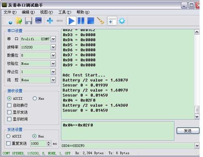
出图效果:参数是默认参数,效果不是很好,但出图是没问题,然后可以直接在串口助手中发送参数,对Sensor效果进行调试,就脱离了软件编译再下载。

STM32F207 两路ADC连续转换及GPIO模拟I2C给Camera Sensor初始化参数
标签:
原文地址:http://www.cnblogs.com/wen2376/p/4528477.html
