标签:
Point to Point Connection
PPP is a protocol that is able to handle authentication, compression, error detection, monitor link quality, and logically bundles multiple serial connections together to share the load.
There are many different serial communication standards, each one using a different signaling method. There are three important serial communication standards affecting LAN-to-WAN connections:
• RS-232 - Most serial ports on personal computers conform to the RS-232C or newer RS-422 and RS-423 standards. Both 9-pin and 25-pin connectors are used. A serial port is a general-purpose interface that can be used for almost any type of device, including modems, mice, and printers. These types of peripheral devices for computers have been replaced by new and faster standards such as USB but many network devices use RJ-45 connectors that conform to the original RS-232 standard.
• V.35 - Typically used for modem-to-multiplexer communication, this ITU standard for high-speed, synchronous data exchange combines the bandwidth of several telephone circuits. In the U.S., V.35 is the interface standard used by most routers and DSUs that connect to T1 carriers. V.35 cables are high-speed serial assemblies designed to support higher data rates and connectivity between DTEs and DCEs over digital lines. There is more on DTEs and DCEs later in this section.
• HSSI - A High-Speed Serial Interface (HSSI) supports transmission rates up to 52 Mb/s. Engineers use HSSI to connect routers on LANs with WANs over high-speed lines, such as T3 lines. Engineers also use HSSI to provide high-speed connectivity between LANs, using Token Ring or Ethernet. HSSI is a DTE/DCE interface developed by Cisco Systems and T3 plus Networking to address the need for high-speed communication over WAN links.
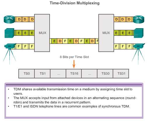
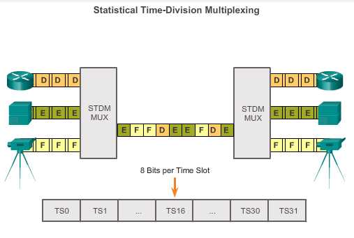
With a leased line, despite the fact that customers are paying for dedicated services, and dedicated bandwidth is provided to the customer, the carrier still uses multiplexing technologies within the network. Multiplexing refers to a scheme that allows multiple logical signals to share a single physical channel. Two common types of multiplexing are time-division multiplexing (TDM) and statistical time-division multiplexing (STDM).
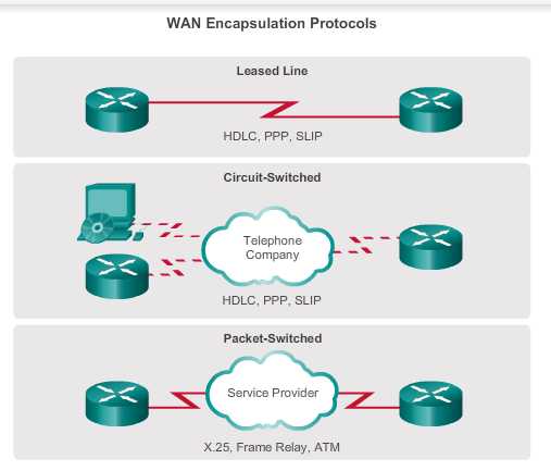
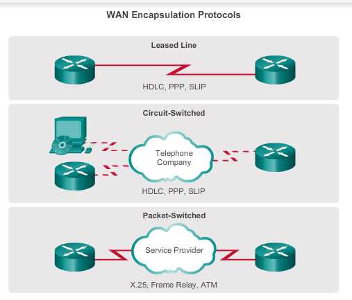
The following are short descriptions of each type of WAN protocol:
• HDLC - The default encapsulation type on point-to-point connections, dedicated links, and circuit-switched connections when the link uses two Cisco devices. HDLC is now the basis for synchronous PPP used by many servers to connect to a WAN, most commonly the Internet.
• PPP - Provides router-to-router and host-to-network connections over synchronous and asynchronous circuits. PPP works with several network layer protocols, such as IPv4 and IPv6. PPP uses the HDLC encapsulation protocol, but also has built-in security mechanisms such as PAP and CHAP.
• Serial Line Internet Protocol (SLIP) - A standard protocol for point-to-point serial connections using TCP/IP. SLIP has been largely displaced by PPP.
• X.25/Link Access Procedure, Balanced (LAPB) - An ITU-T standard that defines how connections between a DTE and DCE are maintained for remote terminal access and computer communications in public data networks. X.25 specifies LAPB, a data link layer protocol. X.25 is a predecessor to Frame Relay.
• Frame Relay - An industry standard, switched, data link layer protocol that handles multiple virtual circuits. Frame Relay is a next generation protocol after X.25. Frame Relay eliminates some of the time-consuming processes (such as error correction and flow control) employed in X.25.
• ATM - The international standard for cell relay in which devices send multiple service types, such as voice, video, or data, in fixed-length (53-byte) cells. Fixed-length cells allow processing to occur in hardware; thereby, reducing transit delays. ATM takes advantage of high-speed transmission media such as E3, SONET, and T3.

HDLC is a bit-oriented synchronous data link layer protocol developed by the International Organization for Standardization (ISO). The current standard for HDLC is ISO 13239. HDLC was developed from the Synchronous Data Link Control (SDLC) standard proposed in the 1970s. HDLC provides both connection-oriented and connectionless service.

Cisco has developed an extension to the HLDC protocol to solve the inability to provide multiprotocol support. Although Cisco HLDC (also referred to as cHDLC) is proprietary, Cisco has allowed many other network equipment vendors to implement it. Cisco HDLC frames contain a field for identifying the network protocol being encapsulated. The figure compares standard HLDC to Cisco HLDC.
Flag
The flag field initiates and terminates error checking. The frame always starts and ends with an 8-bit flag field. The bit pattern is 01111110. Because there is a likelihood that this pattern occurs in the actual data, the sending HDLC system always inserts a 0 bit after every five consecutive 1s in the data field, so in practice the flag sequence can only occur at the frame ends. The receiving system strips out the inserted bits. When frames are transmitted consecutively, the end flag of the first frame is used as the start flag of the next frame.
Address
The address field contains the HDLC address of the secondary station. This address can contain a specific address, a group address, or a broadcast address. A primary address is either a communication source or a destination, which eliminates the need to include the address of the primary.
Control
The control field uses three different formats, depending on the type of HDLC frame used:
Protocol
Only used in Cisco HDLC. This field specifies the protocol type encapsulated within the frame (e.g. 0x0800 for IP).
Data
The data field contains a Path Information Unit (PIU) or Exchange Identification (XID) information.
Frame Check Sequence (FCS)
The FCS precedes the ending flag delimiter and is usually a Cyclic Redundancy Check (CRC) calculation remainder. The CRC calculation is redone in the receiver. If the result differs from the value in the original frame, an error is assumed.
PPP encapsulation has been carefully designed to retain compatibility with most commonly used supporting hardware. PPP encapsulates data frames for transmission over Layer 2 physical links. PPP establishes a direct connection using serial cables, phone lines, trunk lines, cellular telephones, specialized radio links, or fiber-optic links.
PPP contains three main components:
PPP includes many features not available in HDLC:
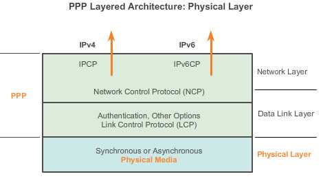
The LCP functions within the data link layer and has a role in establishing, configuring, and testing the data-link connection. The LCP establishes the point-to-point link. The LCP also negotiates and sets up control options on the WAN data link, which are handled by the NCPs.
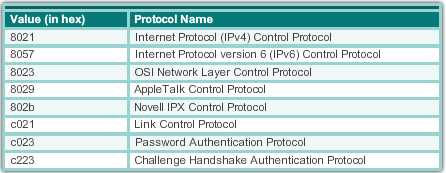
NCPs include functional fields containing standardized codes to indicate the network layer protocol that PPP encapsulates. Figure 2 lists the PPP protocol field numbers. Each NCP manages the specific needs required by its respective network layer protocols. The various NCP components encapsulate and negotiate options for multiple network layer protocols.
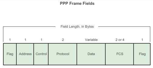
A PPP frame consists of six fields. The following descriptions summarize the PPP frame fields illustrated in the figure:


Enabling PPP on an Interface
To set PPP as the encapsulation method used by a serial interface, use the encapsulation ppp.
The following example enables PPP encapsulation on interface serial 0/0/0:
R3(config)# interface serial 0/0/0
R3(config-if)# encapsulation ppp
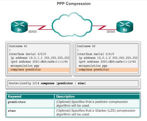
If the link quality percentage is not maintained, the link is deemed to be of poor quality and is taken down. Link Quality Monitoring (LQM) implements a time lag so that the link does not bounce up and down.
The following configuration example monitors the data dropped on the link and avoids frame looping:
R3(config)# interface serial 0/0/0
R3(config-if)# encapsulation ppp
R3(config-if)# ppp quality 80
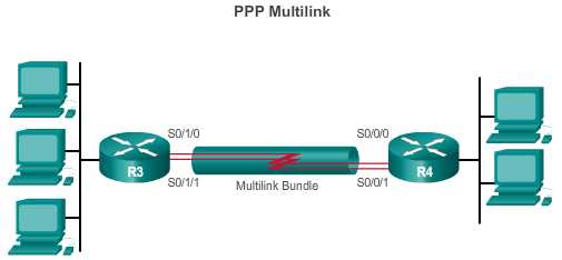
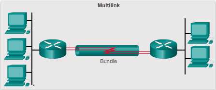
Multilink PPP (also referred to as MP, MPPP, MLP, or Multilink) provides a method for spreading traffic across multiple physical WAN links. Multilink PPP also provides packet fragmentation and reassembly, proper sequencing, multivendor interoperability, and load balancing on inboundand outbound traffic.
Step 1. Create a multilink bundle.
The interface multilink number command creates the multilink interface.
In interface configuration mode, an IP address is assigned to the multilink interface.
The interface is enabled for multilink PPP.
The interface is assigned a multilink group number.
Step 2. Assign interfaces to the multilink bundle.
Each interface that is part of the multilink group:
Is enabled for PPP encapsulation.
Is enabled for multilink PPP.
Is bound to the multilink bundle using the multilink group number configured in Step 1.
Interface multilink 1
Ip address X.X.X.X X.X.X.X
Ppp multilink
Ppp multilink group 1
Int s 0/1/0
No ip address
Encapsulation ppp
Ppp multilink
Ppp multilink group 1
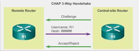
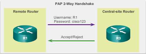
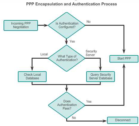
PAP is a very basic two-way process. There is no encryption. The username and password are sent in plaintext. If it is accepted, the connection is allowed. CHAP is more secure than PAP. It involves a three-way exchange of a shared secret.

R1:
Username R2 password someone
Interface s0/0/0
Ip add 10.0.1.1 255.255.255.0
Encapsulation ppp
Ppp authentication pap
Ppp pap sent-username R1 password someone
R2:
Username R2 password someone
Interface s0/0/0
Ip add 10.0.1.1 255.255.255.0
Encapsulation ppp
Ppp authentication pap
Ppp pap sent-username R1 password someone
标签:
原文地址:http://www.cnblogs.com/elewei/p/4662747.html