标签:

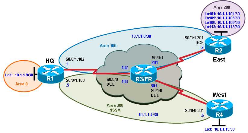
1. Use the addressing scheme shown in the diagram.
2. Configure OSPF with the networks shown in the diagram.
3. Configure the OSPF backbone area to be on Loopback0 on HQ.
4. Configure the Frame Relay subnets as point-to-point subinterfaces, with the link between HQ and East in area 100, and the link between HQ and West in area 300.
5. Configure area 300 as an NSSA.
6. Configure the router East loopback interfaces to be in area 200. Summarize this area with the most efficient summary.
7. Redistribute the loopback network on router West into OSPF.
8. Create virtual links as necessary for full connectivity.
9. Make sure that all loopback interfaces are advertised with the correct subnet mask.
标签:
原文地址:http://www.cnblogs.com/elewei/p/4699248.html